EP2465655B1 - Procédé de vidage d'un silo de grue développé pour la réception et le transport suspendu de matériaux de construction coulants - Google Patents
Procédé de vidage d'un silo de grue développé pour la réception et le transport suspendu de matériaux de construction coulants Download PDFInfo
- Publication number
- EP2465655B1 EP2465655B1 EP10405239.4A EP10405239A EP2465655B1 EP 2465655 B1 EP2465655 B1 EP 2465655B1 EP 10405239 A EP10405239 A EP 10405239A EP 2465655 B1 EP2465655 B1 EP 2465655B1
- Authority
- EP
- European Patent Office
- Prior art keywords
- piston
- cylinder
- delivery
- gas pressure
- gas
- Prior art date
- Legal status (The legal status is an assumption and is not a legal conclusion. Google has not performed a legal analysis and makes no representation as to the accuracy of the status listed.)
- Active
Links
Images


Classifications
-
- E—FIXED CONSTRUCTIONS
- E04—BUILDING
- E04G—SCAFFOLDING; FORMS; SHUTTERING; BUILDING IMPLEMENTS OR AIDS, OR THEIR USE; HANDLING BUILDING MATERIALS ON THE SITE; REPAIRING, BREAKING-UP OR OTHER WORK ON EXISTING BUILDINGS
- E04G21/00—Preparing, conveying, or working-up building materials or building elements in situ; Other devices or measures for constructional work
- E04G21/02—Conveying or working-up concrete or similar masses able to be heaped or cast
- E04G21/025—Buckets specially adapted for use with concrete
-
- B—PERFORMING OPERATIONS; TRANSPORTING
- B65—CONVEYING; PACKING; STORING; HANDLING THIN OR FILAMENTARY MATERIAL
- B65D—CONTAINERS FOR STORAGE OR TRANSPORT OF ARTICLES OR MATERIALS, e.g. BAGS, BARRELS, BOTTLES, BOXES, CANS, CARTONS, CRATES, DRUMS, JARS, TANKS, HOPPERS, FORWARDING CONTAINERS; ACCESSORIES, CLOSURES, OR FITTINGS THEREFOR; PACKAGING ELEMENTS; PACKAGES
- B65D90/00—Component parts, details or accessories for large containers
- B65D90/54—Gates or closures
- B65D90/56—Gates or closures operating by deformation of flexible walls
Definitions
- the invention relates to a method for emptying of a receiving and hanging transport of free-flowing building materials such as concrete, gravel, sand, etc. trained crane silos with a container having at the upper end a filling opening for charging and at the lower end a discharge opening for removal of Building material via a hanging crane arranged on the crane silo and with the discharge opening of the container conveyor effectively connected conveying hose, which is assigned to the one of the emptying opening of the container facing conveyor region for closing and opening adjustable metering device.
- free-flowing building materials such as concrete, gravel, sand, etc. trained crane silos with a container having at the upper end a filling opening for charging and at the lower end a discharge opening for removal of Building material via a hanging crane arranged on the crane silo and with the discharge opening of the container conveyor effectively connected conveying hose, which is assigned to the one of the emptying opening of the container facing conveyor region for closing and opening adjustable metering device.
- a crane silo for carrying out the method according to the aforementioned type is inter alia in the EP 10 405 018.2 described.
- the pre-published EP 1 830 017 A1 relates to a crane silo, with which both easier flowing and viscous materials, especially concrete of different consistency can be processed by different, one of the emptying end of a container of the crane crane attached flap closure selectively deliverable chute or delivery hose.
- the US 4'161'135 A describes a hydraulic drive device, for example, for opening and closing gates by means of actable piston a piston-cylinder unit.
- Such crane silos are used in particular in the processing of concrete, especially self-compacting concrete SCC (Self Compacting Concrete), but also in slow-flowing concrete with such properties.
- SCC Self Compacting Concrete
- the self-compacting concrete has a relatively high liquid content resp. a favorable flowability.
- the self-compacting mass which is self-compacting due to its high dead weight and liquid deposits, is extracted from the crane silo via a delivery hose fed to a turned-on cavity.
- a metering device which is arranged at the upper end of the delivery hose, takes place, for example, for the opening of the metering device by a freely hanging down traction cable, which is preferably actuated by another person.
- Closing the dosing device resp. an interruption of the supply of the building material in the formwork is created by the force of a vorzuspannenden during the opening operation spring.
- the height of the dosing device attached to the crane silo changes. their accessibility and thus the length of the pull rope, so that the concreting -Kranilo and bainschlauch- out of balance respectively. comes from a stable position and thus makes the work of the staff more difficult.
- a complicated handling of the delivery hose has disadvantageous the safety of a construction site and the equipment used and affects the work performance.
- the object of the invention is therefore to provide a method and a crane silo, which ensure a simple and reliable processing of building materials from containers of a crane silo via a delivery hose efficiently and safely.
- the object is achieved in that the opening of the metering device for forming a conveyor cross section on the delivery hose, by means of a piston-cylinder unit acted upon by a hydraulic pump by a with the opening movement of a gas for a biased closing movement of the metering in a counterforce to the opening movement on a Closing pressure compressing, hydraulic force takes place.
- the opening of the metering device for forming a conveying cross section on the delivery hose by one with the opening movement the gas from an expansion space for the purpose of a gas pressure increase in a separate gas pressure accumulator resp.
- Gas pressure vessel transporting, hydraulic force and to close the metering device resp.
- the compressed gas located in the gas pressure accumulator is returned to the expansion space with relaxation of the gas pressure. recycled.
- the inventive method can alternatively be applied by the opening of the metering device for forming a conveyor cross-section of the delivery hose by a with the opening movement of liquid from the expansion space, respectively.
- Cylinder space in a gas pressure accumulator separately surrounding pressure vessel for the purpose of increasing the gas pressure in the gas pressure accumulator transposing, hydraulic force and the closing of the metering device resp. for closing the delivery cross-section of the delivery hose, which is returned in the pressure vessel liquid located under relaxation of the gas pressure in the expansion space.
- the hydraulic force can be generated by supplying a piston guided in a cylinder space of the cylinder of the piston-cylinder unit on one side by means of supplied liquid and at the same time with the back of the piston moved by the hydraulic force from the expansion space liquid under compression effect on the gas pressure accumulator be promoted in the pressure vessel.
- the method can be used with a suitable for this purpose according to the invention Kransilo for the transport of pourable building materials such as concrete, gravel, sand, etc., formed with a material for receiving a building material, at an upper end of a filling opening for charging and at a lower end a discharge opening provided for removal of the building material via a hanging attached conveyor hose having container and which is connected to a detachable support frame, wherein below the container in the emptying direction to the Emptying opening is then arranged, an acting on the delivery hose for changing the conveyor cross-section, adjustable metering device is connected to the actuation with a drive shaft, wherein the crane silo according to the invention is characterized in that the drive shaft of an actuator with a piston-cylinder unit in two Cylinder spaces separating piston drivingly connected and the first cylinder space of the cylinder of the piston-cylinder unit before resp. behind the piston for receiving a liquid medium with a controllable hydraulic pump line connected and the cylinder chamber behind resp. connected in front of the piston
- the second cylinder space for receiving a gaseous medium for example nitrogen, is connected to a gas pressure vessel.
- the drive devices according to the invention offer a considerable advantage in terms of reliability and maintenance.
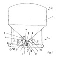
- the Fig. 1 shows in excerpts a crane silo 1 for the transport of pourable building materials such as concrete, gravel, sand or the like.
- a container 2 which is cylindrical in the upper region, but could also have a polygonal cross-section, such as the execution of a crane silo in the CH 685 831 A5 , and its container wall resp. -walls to a lower discharge opening 3 towards approximately conical or pyramidal resp. funnel-like, the container 2 tapering, run.
- the upper end of the container 2 (not visible) is as a filling opening 3 for charging the container 2 and the lower end formed with the discharge opening 3 for removing a building material.
- the emptying opening 3 is provided for example with a nozzle 4, to which a conveyor hose 5 shown in broken lines by means of a connecting piece 4 surrounding Bride 6 is attached hanging .
- the crane silo 1 is designed to remove the building materials via a delivery hose 5, in a transverse to the conveying direction of the building materials compressed state is shown.
- the crane silo 1 for loading the container 2 has a support frame 7 which can be placed on the floor and to which the container 2 is fastened.
- an adjustable metering device 8 acting on the downwardly hanging delivery hose 5 for changing the delivery cross section is arranged.
- the metering device 8 is detachably fastened to the outside of the lower container region narrowing in the conveying direction by connecting elements 9, for which purpose a screw connection 10 is provided in each case. It would also be possible to attach the metering device 8 to other parts of the crane silo 1, for example to the support frame 7.
- a metering device 8 at a like in the CH 685831 A5 described to be subsequently grown with a trained below the emptying opening flap closure Kransilo to make a promotion of building materials via a delivery hose can.
- the dosing device 8 surrounding the delivery hose (at least partially) could be attached to a closure device of the container, for example a flap closure of a crane silo after CH 685 831 A5 be releasably attached, so that an optional use of this crane silos-such as in EP 10 405 018.2 disclosed- is possible.
- the metering device 8 has attached to a frame 11, from both sides the downwardly directed (hanging) conveying hose 5 delivery and foundedversetzbare Dosierbalken 12, 13, which are connected to an actuating device 14.
- Fig. 3 the metering device 8 is illustrated on an enlarged scale.
- the frame 11 consists of two spaced side plates 15, 16, held together by transverse rods 17, 18, 19 and screw connections 10 resp. are connected and stabilize the frame 11.
- the on the delivery hose 5 (in Fig. 3 not apparent) deliverable and Wegsetzsetzbaren Dosierbalken 12, 13 are located in Fig. 3 in the operating position according to Fig. 1 , in which the flow of the building materials in the delivery hose 5 is interrupted.
- the metering bars 12, 13 are in accordance with Fig. 1 approximately evenly distributed on the conveyor cross section of the delivery hose 5, laterally held away from each other (Dosierbalken 12 'and 13') and make the delivery hose 5 to flow freely. If the delivery flow in the delivery hose 5 is interrupted, the metering bars 12, 13 take their into the Fig. 1 and 3 shown position and press the intermediate conveying hose 5 flat together.
- both Dosierbalken 12, 13 are moved against each other and are for this purpose on pivot arms 21, 22 mounted in the frame 11 pendulum.
- the pivot arms 21, 22 each have a common pivot axis 23, 24, which are arranged opposite one another in pivot bearings 25, 26 on the frame plates 15, 16, wherein the suspension of Dosierbalken 12, 13 on a common axis is not mandatory.
- the Dosierbalken 12, 13 in compressed, formed mainly of rubber, plastic and fabric conveying hose 5 in the Offset longitudinal extent, ie arranged differently in height, so that the conveyor hose 5 can be gently pressed together and is not exposed to a by pressing together the Dosierbalken 12, 13 resulting harmful pressure.
- the effective region of the metering bars 12, 13 occurring larger stones in the conveying hose 5 can be displaced in the conveying direction, so that also liquid and fines of the building material remain on the metering device 8.
- the Dosierbalken 12 and / or 13 are connected to lever gears 27, 28 of the actuator 14, wherein the connection points are formed by a respective steering lever 29, 30 of the lever mechanism 27, 28 and the pivotable end of the pivot arms 21, 22.
- the steering levers 29, 30 are with their opposite ends respectively at the free ends of the lever arms 31, respectively.
- the latter is each mounted in a side plate 15, 16 of the frame 11 and drivingly connected to the mounted in the opposite side plate 16, 15 Doppelarmhebel 33.
- the actuation of the lever mechanism 27, 28 by means of a in Fig. 2 shown drive device 34, which with a drive shaft 20 (see Fig. 1 to 3 ) of the actuator 14 is drivingly connected.
- the mirror-image opposing, similar lever mechanism 27, 28 are respectively disposed on the Souiten15, 16 within the frame 11, so that they are protected against external influences and the surrounding area.
- drive device 34 acting on the drive shaft 20 of the actuator 14 of the metering device 8 drive device 34 consists of a piston-cylinder unit 35, the piston 36, the cylinder in a first cylinder chamber 37 and in a second cylinder chamber 38 separates.
- the piston-cylinder unit 35 is preferably pivotally connected at the upper end to the support frame 7 or the container 2 of the crane silo 1.
- the piston 36 has a piston rod 39, which in the direction of movement of the piston 36, a lower cylinder bottom 40 passes through tightly and is connected at the opposite end of the piston 36 with a fixed to the drive shaft 20 lever 41 gelchanbusend.
- the first cylinder chamber 37 is line connected to the liquid intake with a hydraulic pump 42, which in turn driven by an electric motor and by a mobile control device 43 via a control device 44 remotely controllable resp. is remotely controlled.
- An electric motor (not shown) drivingly connected to the hydraulic pump 42 is connected to an electric power source such as an accumulator (not shown).
- the second cylinder chamber 38 is connected via line 45 with a gas pressure accumulator 46, in the gas, for example, liquid nitrogen, by the out of the hydraulic pump 42 in the first cylinder chamber 37 to the piston 36 guided liquid into the gas reservoir 46 to achieve a high gas pressure preloaded counterforce is displaced to the hydraulic force.
- the gas pressure accumulator 46 may be formed as a pressure bottle and attached to the support frame 7 of the crane silo 1.
- gas preferably nitrogen
- the mass of the conveyor cross section in the delivery hose 5, respectively. the flow rate can be determined and changed. If the supply of liquid for the hydraulic force is interrupted and the liquid, for example, returned to a collecting container 48, the gas pressure in the gas pressure accumulator 46, the line 45 and the second cylinder chamber 38 formed line resp. Gas guide assembly, and the piston 36, gas-loaded at the back, displaced with a lifting movement liquid from the first cylinder chamber 37 via the hydraulic pump 42 in the collecting container 48 back, or in a by-pass line (not shown).
- the drive device 34 could also be formed by a valve arrangement, with which the metering device 8 is driven via the drive shaft 20.
- the closing process can take place in accordance with the relaxation of the gas pressure abruptly.
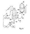
- Fig. 4 shows an alternative drive device 34 for actuating the metering device 8 of the crane silo 1.
- the difference with respect to the drive device 34 in Fig. 2 essentially lies in the fact that the second cylinder chamber 38, which also as in the case of the drive device 34, after Fig. 2 could be arranged on the opposite side of the piston 36 of the piston-cylinder unit 35, with a gas reservoir 49 having a pressure vessel 50 a pressure fluid leading, such as hydraulic oil, line connected.
- the gas reservoir 49 may be formed as a bubble, membrane or piston accumulator.
- the in Fig. 4 illustrated bubble memory 49 is shown in two positions. With the solid line, the bubble is in a VorHolldruck ein in which it is filled with nitrogen and resting on a poppet valve 51, the mouth of the conduit 45, which connects the cylinder chamber 38 of the piston-cylinder unit 35 with the pressure vessel 50, closes.
- the dashed line mediates the bubble under working pressure resp. increased pressure by the supplied from the cylinder chamber 38 in the pressure vessel 50 hydraulic fluid.
- the volume change of the bubble between the position at minimum and maximum working pressure corresponds to the stored amount of liquid.
- the bladder Via a filling valve 52, the bladder can be filled with nitrogen and then takes the form in the Vor colll ein. As pressurized fluid is delivered into the pressure vessel 50, the nitrogen in the bladder 49 is compressed, that is, the gas volume decreases and the pressure is increased.
- the hydraulic force directed by the feed pump 42 onto the piston 36 of the piston-cylinder unit 35 can be interrupted by the supplied hydraulic fluid or reversed in a circuit of the hydraulic fluid (not shown) in the case of a directional control valve arrangement.
- the prestressed bladder 49 thereby expands and pushes the pressurized fluid back into the second cylinder chamber 38 until the bladder 49 again abuts against the fluid valve so that the pressurized fluid is blocked in the pressure vessel 50, with the piston 36 returning at the same time and the material being conveyed through closure the metering device 8 is interrupted.
- the pressure vessel 50 could be provided with a diaphragm (not shown), which, like the bladder, at the filling end of the pressure vessel 50 for the pressurized liquid at the opposite end is fixed in the pressure vessel 50 and filled with nitrogen.
- the membrane On the side facing the filling end, the membrane has a fixed plate, which forms a valve with the end of the line 45. The operation of the membrane memory corresponds to the mentioned difference the bladder memory.
- a piston accumulator which has a cylinder connected to the line 45, which a piston separates into a nitrogen-enriched gas space and, facing away from the latter, into a pressure fluid space, to which the pressure line 45 adjoins.
- the drive devices described allow a metered, even continuous opening a metering device, which can be closed by the closing pressure generated abruptly and with sufficient force.
Landscapes
- Engineering & Computer Science (AREA)
- Architecture (AREA)
- Mechanical Engineering (AREA)
- Civil Engineering (AREA)
- Structural Engineering (AREA)
- Filling Or Emptying Of Bunkers, Hoppers, And Tanks (AREA)
Claims (15)
- Procédé de vidage d'un godet de grue dévolu à la réception et au transport suspendu de matériaux de construction aptes au déversement en vrac, tels que du béton, du gravillon, du sable, etc., et doté d'un réceptacle muni, à l'extrémité supérieure, d'un orifice de remplissage dédié à l'alimentation et, à l'extrémité inférieure, d'un orifice de vidage dédié au prélèvement du matériau de construction par l'intermédiaire d'un tuyau convoyeur souple installé en suspension sur ledit godet de grue, en liaison opérante de convoyage avec l'orifice de vidage du réceptacle, et auquel un dispositif de dosage, réglable en vue de la fermeture et de l'ouverture, est affecté dans la zone de convoyage tournée vers ledit orifice de vidage du réceptacle, caractérisé par le fait que l'ouverture du dispositif de dosage, en vue de l'instauration d'une section transversale de convoyage sur le tuyau convoyeur souple, s'opère au moyen d'un vérin pouvant être sollicité par une pompe hydraulique, sous l'action d'une force hydraulique qui, concurremment au mouvement d'ouverture, comprime un gaz, assigné à un mouvement précontraint de fermeture dudit dispositif de dosage, en une force antagoniste ciblant ledit mouvement d'ouverture, jusqu'à une pression de fermeture.
- Procédé selon la revendication 1, caractérisé par le fait que l'ouverture du dispositif de dosage, ciblant l'instauration d'une section transversale de convoyage sur le tuyau convoyeur souple, s'opère sous l'action d'une force hydraulique qui charrie un gaz provenant d'une chambre d'expansion, concurremment au mouvement d'ouverture, en vue d'obtenir une pression gazeuse accrue régnant, respectivement, dans un accumulateur de pression gazeuse ou dans un récipient sous pression gazeuse implanté distinctement ; et par le fait qu'en vue de la fermeture dudit dispositif de dosage ou, respectivement, de l'obturation de ladite section transversale de convoyage du tuyau convoyeur souple, le gaz comprimé situé dans ledit accumulateur de pression gazeuse est réintroduit dans ladite chambre d'expansion avec détente de ladite pression gazeuse.
- Procédé selon la revendication 2, caractérisé par le fait que la force hydraulique est engendrée par sollicitation unilatérale, au moyen d'un fluide admis, d'un piston guidé dans une chambre cylindrique d'un vérin ; et du gaz, provenant de la chambre d'expansion formée par ledit vérin, est simultanément refoulé vers ledit accumulateur de pression gazeuse, par effet de compression, au moyen de la face postérieure dudit piston mû par la force hydraulique.
- Procédé selon la revendication 1, caractérisé par le fait que l'ouverture du dispositif de dosage, ciblant l'instauration d'une section transversale de convoyage sur le tuyau convoyeur souple, s'opère sous l'action d'une force hydraulique par laquelle, concurremment au mouvement d'ouverture, du fluide, provenant respectivement de la chambre d'expansion ou de la chambre cylindrique, est charrié vers un récipient sous pression entourant distinctement un accumulateur de pression gazeuse, en vue d'obtenir un accroissement de la pression gazeuse régnant dans ledit accumulateur de pression gazeuse ; et par le fait qu'en vue de la fermeture dudit dispositif de dosage ou, respectivement, de l'obturation de ladite section transversale de convoyage du tuyau convoyeur souple, le fluide situé dans ledit récipient sous pression est réintroduit dans ladite chambre d'expansion avec détente de ladite pression gazeuse.
- Procédé selon la revendication 4, caractérisé par le fait que la force hydraulique est engendrée par sollicitation unilatérale, au moyen d'un fluide admis, d'un piston guidé dans une chambre du cylindre du vérin ; et du fluide provenant de la chambre d'expansion est simultanément refoulé vers le récipient sous pression, par effet de compression agissant sur l'accumulateur de pression gazeuse, au moyen de la face postérieure dudit piston mû par la force hydraulique.
- Godet de grue (1) dévolu au transport de matériaux de construction aptes au déversement en vrac, tels que du béton, du gravillon, du sable, etc., et doté d'un réceptacle (2) qui est conçu pour recevoir un matériau de construction, est muni d'un orifice de remplissage dédié à l'alimentation à une extrémité supérieure et, à une extrémité inférieure, d'un orifice de vidage (3) dédié au prélèvement dudit matériau de construction par l'intermédiaire d'un tuyau convoyeur souple (5) fixé en suspension, et est relié à un châssis de support (7) arrêtable, sachant qu'un dispositif réglable de dosage (8), placé dans la continuité directe dudit orifice de vidage (3), au-dessous dudit réceptacle (2) dans la direction du vidage, et agissant sur ledit tuyau convoyeur souple (5) afin de modifier la section transversale de convoyage, est relié à un arbre d'entraînement (20) en vue de l'actionnement, caractérisé par le fait que l'arbre d'entraînement (20) d'un dispositif d'actionnement (14) est en liaison d'entraînement avec un piston (36) scindant un vérin (35) en deux chambres cylindriques, la première chambre (37) du cylindre dudit vérin (35), respectivement située devant ou derrière le piston (36), étant en liaison par conduit avec une pompe hydraulique (42) commandable, de manière à recevoir un agent liquide, et la chambre cylindrique (38), respectivement située derrière ou devant ledit piston (36), étant raccordée à un accumulateur de gaz (49) réalisé en tant que moyen de contre-pression, de manière à engendrer une pression de fermeture.
- Godet de grue selon la revendication 6, caractérisé par le fait que la chambre d'expansion ou, respectivement, la première ou la seconde chambre cylindrique considérée (37, 38), est en liaison par conduit avec un récipient sous pression (50) entourant distinctement un accumulateur de gaz (49).
- Godet de grue selon la revendication 7, caractérisé par le fait que le récipient sous pression (50) est réalisé sous la forme d'un accumulateur à vessie, à diaphragme ou à piston.
- Godet de grue selon l'une des revendications 6 à 8, caractérisé par le fait que la seconde ou la première chambre cylindrique considérée (38, 37) est respectivement raccordée à un récipient (46) sous pression gazeuse ou à un récipient sous pression (50), en vue de recevoir un agent respectivement gazeux ou liquide.
- Godet de grue selon l'une des revendications 6 à 9, caractérisé par le fait que le piston (36) est pourvu, du côté tourné respectivement à l'opposé de la première (37) ou seconde chambre cylindrique, d'une tige (39) qui traverse le fond (40) du cylindre respectif de ladite seconde (38) ou première chambre cylindrique, et est reliée à l'une des extrémités d'un levier (41) à bras unique, fixé à l'arbre d'entraînement (20) par l'autre extrémité.
- Godet de grue selon la revendication 10, caractérisé par le fait que le vérin (35) est, de préférence, relié au châssis de support (7) par une extrémité ; et par le fait que les chambres cylindriques (37, 38) sont respectivement raccordées, par l'intermédiaire de conduits flexibles, à la pompe de refoulement (42) ou à un distributeur commandable, et au moyen de contre-pression.
- Godet de grue selon l'une des revendications 6 à 11, caractérisé par le fait que la pompe de refoulement (42) est en liaison par conduit, au moins côté aspiration, avec un récipient (48) de réception de liquide.
- Godet de grue selon l'une des revendications 6 à 12, caractérisé par le fait que la pompe de refoulement (42), ou le distributeur branché dans un circuit de ladite pompe de refoulement et dévolu à l'actionnement de l'arbre d'entraînement (20), est respectivement connecté(e) à un accumulateur électrique et est de réalisation pilotable à distance, par l'intermédiaire d'un dispositif de commande (44).
- Godet de grue selon l'une des revendications 6 à 13, caractérisé par le fait que la seconde ou la première chambre cylindrique considérée (38, 37) du vérin (35) est respectivement raccordée, par l'intermédiaire d'un conduit flexible (45) à gaz ou à liquide, au récipient (46) sous pression gazeuse ou au récipient sous pression d'un accumulateur à vessie, à diaphragme ou à piston, de préférence fixé au châssis de support (7).
- Godet de grue selon la revendication 14, caractérisé par le fait que le conduit (45) raccordant, respectivement, la première ou la seconde chambre cylindrique considérée (37, 38) du vérin (35) et le récipient (46) sous pression gazeuse, ou le récipient sous pression, est doté d'un raccord de remplissage (47) destiné à l'agent gazeux.
Priority Applications (1)
| Application Number | Priority Date | Filing Date | Title |
|---|---|---|---|
| EP10405239.4A EP2465655B1 (fr) | 2010-12-18 | 2010-12-18 | Procédé de vidage d'un silo de grue développé pour la réception et le transport suspendu de matériaux de construction coulants |
Applications Claiming Priority (1)
| Application Number | Priority Date | Filing Date | Title |
|---|---|---|---|
| EP10405239.4A EP2465655B1 (fr) | 2010-12-18 | 2010-12-18 | Procédé de vidage d'un silo de grue développé pour la réception et le transport suspendu de matériaux de construction coulants |
Publications (2)
| Publication Number | Publication Date |
|---|---|
| EP2465655A1 EP2465655A1 (fr) | 2012-06-20 |
| EP2465655B1 true EP2465655B1 (fr) | 2015-02-18 |
Family
ID=44280730
Family Applications (1)
| Application Number | Title | Priority Date | Filing Date |
|---|---|---|---|
| EP10405239.4A Active EP2465655B1 (fr) | 2010-12-18 | 2010-12-18 | Procédé de vidage d'un silo de grue développé pour la réception et le transport suspendu de matériaux de construction coulants |
Country Status (1)
| Country | Link |
|---|---|
| EP (1) | EP2465655B1 (fr) |
Families Citing this family (5)
| Publication number | Priority date | Publication date | Assignee | Title |
|---|---|---|---|---|
| EP2803784A1 (fr) | 2013-05-12 | 2014-11-19 | Constreq GmbH | Silo de grue pour le transport de matériaux de construction granulaires, comme le béton, le gravier, le sable ou analogues |
| CN103507817B (zh) * | 2013-09-05 | 2016-08-17 | 山西路桥建设集团有限公司 | 简易轨道式混凝土运输装置 |
| EP2905397B1 (fr) | 2014-02-07 | 2016-09-21 | Obrist Baugeräte AG | Silo de grue pour le transport de matériaux de construction coulants, comme le béton, les graviers, le sable ou analogues |
| CN104176401A (zh) * | 2014-07-25 | 2014-12-03 | 合肥三冠包装科技有限公司 | 一种料仓门驱动机构 |
| CN112595269B (zh) * | 2020-12-14 | 2022-11-22 | 重庆建筑工程职业学院 | 一种房地产建筑面积测量装置 |
Family Cites Families (6)
| Publication number | Priority date | Publication date | Assignee | Title |
|---|---|---|---|---|
| US4161135A (en) * | 1977-03-10 | 1979-07-17 | Garlinghouse Roland E | Fail safe fluid power device |
| US4432578A (en) * | 1980-01-11 | 1984-02-21 | Garlinghouse Roland E | Closed pressure actuated system for placement bucket |
| JPH03286070A (ja) * | 1990-03-31 | 1991-12-17 | Fudo Constr Co Ltd | コンクリートバケット装置 |
| DE9006136U1 (de) * | 1990-05-31 | 1990-09-20 | Hebing Metall-Technik GmbH, 46397 Bocholt | Transportbehälter für Beton od.dgl. |
| CH685831A5 (de) | 1994-01-17 | 1995-10-13 | Eduard Voegtli | Einrichtung zum Transport von schüttfähigen Baumaterialien bzw. Baustoffen. |
| ATE519002T1 (de) * | 2006-03-02 | 2011-08-15 | Obrist Baugeraete Ag | Kransilo für den transport von schüttfähigen baustoffen, wie beton, kies, sand oder dgl. |
-
2010
- 2010-12-18 EP EP10405239.4A patent/EP2465655B1/fr active Active
Also Published As
| Publication number | Publication date |
|---|---|
| EP2465655A1 (fr) | 2012-06-20 |
Similar Documents
| Publication | Publication Date | Title |
|---|---|---|
| EP2465655B1 (fr) | Procédé de vidage d'un silo de grue développé pour la réception et le transport suspendu de matériaux de construction coulants | |
| EP3440010B1 (fr) | Dispositif de vidange de substances visqueuses et procédé associé | |
| EP1056589A1 (fr) | Procede permettant de faire fonctionner une presse a paquets par cisaillement et presse a paquets par cisaillement | |
| EP3168472B1 (fr) | Installation de remplissage pour mousse isolante minérale | |
| EP2535482B1 (fr) | Silo de grue pour le transport de matériaux de construction coulants, comme le béton, les graviers, le sable ou analogues | |
| EP2987909A2 (fr) | Rouleau compresseur | |
| EP2848579B1 (fr) | Dispositif pour remplir un produit dans un récipient à remplir | |
| EP2987908B1 (fr) | Rouleau compresseur | |
| EP0315750B1 (fr) | Pompe pour matière épaisse | |
| EP3911801A1 (fr) | Arrangement vibrateur pour l'amélioration du sol de fondation | |
| EP1830017B1 (fr) | Benne pour le transport de matériaux de construction en vrac, comme béton, gravillons, sable | |
| DE4340235C2 (de) | Vorrichtung zum kontinuierlichen Abführen viskoser Materialien aus Behältern | |
| EP2980334B1 (fr) | Silo de grue pour le transport et le traitement de matériaux de construction coulants | |
| EP2152586B1 (fr) | Emballeuse | |
| AT508287B1 (de) | Vorrichtung zum pressen und fördern von ballen, insbesondere aus altstoffen | |
| EP2699742B1 (fr) | Agencement et procédé pour la production des éléments en béton | |
| EP0830926A2 (fr) | Conteneur pour béton | |
| EP0988450A1 (fr) | Pompe a liquides epais comportant deux cylindres | |
| EP2103742B1 (fr) | Agitateur destiné à la fabrication de colonnes de matériau dans le sol | |
| DE4440335B4 (de) | Beschickungsvorrichtung für Schüttgut | |
| CH707015B1 (de) | Verfahren zum Befüllen einer Schalung mit Beton. | |
| EP2803784A1 (fr) | Silo de grue pour le transport de matériaux de construction granulaires, comme le béton, le gravier, le sable ou analogues | |
| DE20311067U1 (de) | Vorrichtung zur Vorhaltung und Handhabung von Schüttgütern | |
| DE1531769C (de) | Müllstauvorrichtung an Müllfahrzeugen oder -anhängern | |
| EP1235961A1 (fr) | Procede et dispositif de betonnage de puits verticaux |
Legal Events
| Date | Code | Title | Description |
|---|---|---|---|
| PUAI | Public reference made under article 153(3) epc to a published international application that has entered the european phase |
Free format text: ORIGINAL CODE: 0009012 |
|
| AK | Designated contracting states |
Kind code of ref document: A1 Designated state(s): AL AT BE BG CH CY CZ DE DK EE ES FI FR GB GR HR HU IE IS IT LI LT LU LV MC MK MT NL NO PL PT RO RS SE SI SK SM TR |
|
| AX | Request for extension of the european patent |
Extension state: BA ME |
|
| 17P | Request for examination filed |
Effective date: 20121129 |
|
| REG | Reference to a national code |
Ref country code: DE Ref legal event code: R079 Ref document number: 502010008897 Country of ref document: DE Free format text: PREVIOUS MAIN CLASS: B28C0007160000 Ipc: E04G0021020000 |
|
| GRAP | Despatch of communication of intention to grant a patent |
Free format text: ORIGINAL CODE: EPIDOSNIGR1 |
|
| RIC1 | Information provided on ipc code assigned before grant |
Ipc: E04G 21/02 20060101AFI20140731BHEP Ipc: B65D 90/66 20060101ALI20140731BHEP Ipc: B65D 90/56 20060101ALI20140731BHEP |
|
| INTG | Intention to grant announced |
Effective date: 20140820 |
|
| GRAS | Grant fee paid |
Free format text: ORIGINAL CODE: EPIDOSNIGR3 |
|
| GRAA | (expected) grant |
Free format text: ORIGINAL CODE: 0009210 |
|
| AK | Designated contracting states |
Kind code of ref document: B1 Designated state(s): AL AT BE BG CH CY CZ DE DK EE ES FI FR GB GR HR HU IE IS IT LI LT LU LV MC MK MT NL NO PL PT RO RS SE SI SK SM TR |
|
| REG | Reference to a national code |
Ref country code: GB Ref legal event code: FG4D Free format text: NOT ENGLISH |
|
| REG | Reference to a national code |
Ref country code: CH Ref legal event code: EP |
|
| REG | Reference to a national code |
Ref country code: AT Ref legal event code: REF Ref document number: 710750 Country of ref document: AT Kind code of ref document: T Effective date: 20150315 |
|
| REG | Reference to a national code |
Ref country code: IE Ref legal event code: FG4D Free format text: LANGUAGE OF EP DOCUMENT: GERMAN |
|
| REG | Reference to a national code |
Ref country code: DE Ref legal event code: R096 Ref document number: 502010008897 Country of ref document: DE Effective date: 20150402 |
|
| REG | Reference to a national code |
Ref country code: CH Ref legal event code: NV Representative=s name: WERNER FENNER PATENTANWALT, CH |
|
| REG | Reference to a national code |
Ref country code: NL Ref legal event code: VDEP Effective date: 20150218 |
|
| REG | Reference to a national code |
Ref country code: LT Ref legal event code: MG4D |
|
| PG25 | Lapsed in a contracting state [announced via postgrant information from national office to epo] |
Ref country code: HR Free format text: LAPSE BECAUSE OF FAILURE TO SUBMIT A TRANSLATION OF THE DESCRIPTION OR TO PAY THE FEE WITHIN THE PRESCRIBED TIME-LIMIT Effective date: 20150218 Ref country code: ES Free format text: LAPSE BECAUSE OF FAILURE TO SUBMIT A TRANSLATION OF THE DESCRIPTION OR TO PAY THE FEE WITHIN THE PRESCRIBED TIME-LIMIT Effective date: 20150218 Ref country code: FI Free format text: LAPSE BECAUSE OF FAILURE TO SUBMIT A TRANSLATION OF THE DESCRIPTION OR TO PAY THE FEE WITHIN THE PRESCRIBED TIME-LIMIT Effective date: 20150218 Ref country code: SE Free format text: LAPSE BECAUSE OF FAILURE TO SUBMIT A TRANSLATION OF THE DESCRIPTION OR TO PAY THE FEE WITHIN THE PRESCRIBED TIME-LIMIT Effective date: 20150218 Ref country code: LT Free format text: LAPSE BECAUSE OF FAILURE TO SUBMIT A TRANSLATION OF THE DESCRIPTION OR TO PAY THE FEE WITHIN THE PRESCRIBED TIME-LIMIT Effective date: 20150218 Ref country code: NO Free format text: LAPSE BECAUSE OF FAILURE TO SUBMIT A TRANSLATION OF THE DESCRIPTION OR TO PAY THE FEE WITHIN THE PRESCRIBED TIME-LIMIT Effective date: 20150518 |
|
| PG25 | Lapsed in a contracting state [announced via postgrant information from national office to epo] |
Ref country code: NL Free format text: LAPSE BECAUSE OF FAILURE TO SUBMIT A TRANSLATION OF THE DESCRIPTION OR TO PAY THE FEE WITHIN THE PRESCRIBED TIME-LIMIT Effective date: 20150218 Ref country code: RS Free format text: LAPSE BECAUSE OF FAILURE TO SUBMIT A TRANSLATION OF THE DESCRIPTION OR TO PAY THE FEE WITHIN THE PRESCRIBED TIME-LIMIT Effective date: 20150218 Ref country code: IS Free format text: LAPSE BECAUSE OF FAILURE TO SUBMIT A TRANSLATION OF THE DESCRIPTION OR TO PAY THE FEE WITHIN THE PRESCRIBED TIME-LIMIT Effective date: 20150618 Ref country code: LV Free format text: LAPSE BECAUSE OF FAILURE TO SUBMIT A TRANSLATION OF THE DESCRIPTION OR TO PAY THE FEE WITHIN THE PRESCRIBED TIME-LIMIT Effective date: 20150218 Ref country code: GR Free format text: LAPSE BECAUSE OF FAILURE TO SUBMIT A TRANSLATION OF THE DESCRIPTION OR TO PAY THE FEE WITHIN THE PRESCRIBED TIME-LIMIT Effective date: 20150519 |
|
| PG25 | Lapsed in a contracting state [announced via postgrant information from national office to epo] |
Ref country code: CZ Free format text: LAPSE BECAUSE OF FAILURE TO SUBMIT A TRANSLATION OF THE DESCRIPTION OR TO PAY THE FEE WITHIN THE PRESCRIBED TIME-LIMIT Effective date: 20150218 Ref country code: EE Free format text: LAPSE BECAUSE OF FAILURE TO SUBMIT A TRANSLATION OF THE DESCRIPTION OR TO PAY THE FEE WITHIN THE PRESCRIBED TIME-LIMIT Effective date: 20150218 Ref country code: DK Free format text: LAPSE BECAUSE OF FAILURE TO SUBMIT A TRANSLATION OF THE DESCRIPTION OR TO PAY THE FEE WITHIN THE PRESCRIBED TIME-LIMIT Effective date: 20150218 Ref country code: RO Free format text: LAPSE BECAUSE OF FAILURE TO SUBMIT A TRANSLATION OF THE DESCRIPTION OR TO PAY THE FEE WITHIN THE PRESCRIBED TIME-LIMIT Effective date: 20150218 Ref country code: SK Free format text: LAPSE BECAUSE OF FAILURE TO SUBMIT A TRANSLATION OF THE DESCRIPTION OR TO PAY THE FEE WITHIN THE PRESCRIBED TIME-LIMIT Effective date: 20150218 |
|
| REG | Reference to a national code |
Ref country code: DE Ref legal event code: R097 Ref document number: 502010008897 Country of ref document: DE |
|
| PG25 | Lapsed in a contracting state [announced via postgrant information from national office to epo] |
Ref country code: PL Free format text: LAPSE BECAUSE OF FAILURE TO SUBMIT A TRANSLATION OF THE DESCRIPTION OR TO PAY THE FEE WITHIN THE PRESCRIBED TIME-LIMIT Effective date: 20150218 |
|
| PLBE | No opposition filed within time limit |
Free format text: ORIGINAL CODE: 0009261 |
|
| STAA | Information on the status of an ep patent application or granted ep patent |
Free format text: STATUS: NO OPPOSITION FILED WITHIN TIME LIMIT |
|
| 26N | No opposition filed |
Effective date: 20151119 |
|
| PG25 | Lapsed in a contracting state [announced via postgrant information from national office to epo] |
Ref country code: SI Free format text: LAPSE BECAUSE OF FAILURE TO SUBMIT A TRANSLATION OF THE DESCRIPTION OR TO PAY THE FEE WITHIN THE PRESCRIBED TIME-LIMIT Effective date: 20150218 |
|
| PG25 | Lapsed in a contracting state [announced via postgrant information from national office to epo] |
Ref country code: BE Free format text: LAPSE BECAUSE OF NON-PAYMENT OF DUE FEES Effective date: 20151231 |
|
| PG25 | Lapsed in a contracting state [announced via postgrant information from national office to epo] |
Ref country code: MC Free format text: LAPSE BECAUSE OF FAILURE TO SUBMIT A TRANSLATION OF THE DESCRIPTION OR TO PAY THE FEE WITHIN THE PRESCRIBED TIME-LIMIT Effective date: 20150218 Ref country code: LU Free format text: LAPSE BECAUSE OF FAILURE TO SUBMIT A TRANSLATION OF THE DESCRIPTION OR TO PAY THE FEE WITHIN THE PRESCRIBED TIME-LIMIT Effective date: 20151218 |
|
| GBPC | Gb: european patent ceased through non-payment of renewal fee |
Effective date: 20151218 |
|
| REG | Reference to a national code |
Ref country code: IE Ref legal event code: MM4A |
|
| REG | Reference to a national code |
Ref country code: FR Ref legal event code: ST Effective date: 20160831 |
|
| PG25 | Lapsed in a contracting state [announced via postgrant information from national office to epo] |
Ref country code: GB Free format text: LAPSE BECAUSE OF NON-PAYMENT OF DUE FEES Effective date: 20151218 Ref country code: IE Free format text: LAPSE BECAUSE OF NON-PAYMENT OF DUE FEES Effective date: 20151218 |
|
| PG25 | Lapsed in a contracting state [announced via postgrant information from national office to epo] |
Ref country code: FR Free format text: LAPSE BECAUSE OF NON-PAYMENT OF DUE FEES Effective date: 20151231 |
|
| PG25 | Lapsed in a contracting state [announced via postgrant information from national office to epo] |
Ref country code: HU Free format text: LAPSE BECAUSE OF FAILURE TO SUBMIT A TRANSLATION OF THE DESCRIPTION OR TO PAY THE FEE WITHIN THE PRESCRIBED TIME-LIMIT; INVALID AB INITIO Effective date: 20101218 Ref country code: BG Free format text: LAPSE BECAUSE OF FAILURE TO SUBMIT A TRANSLATION OF THE DESCRIPTION OR TO PAY THE FEE WITHIN THE PRESCRIBED TIME-LIMIT Effective date: 20150218 Ref country code: SM Free format text: LAPSE BECAUSE OF FAILURE TO SUBMIT A TRANSLATION OF THE DESCRIPTION OR TO PAY THE FEE WITHIN THE PRESCRIBED TIME-LIMIT Effective date: 20150218 |
|
| PG25 | Lapsed in a contracting state [announced via postgrant information from national office to epo] |
Ref country code: CY Free format text: LAPSE BECAUSE OF FAILURE TO SUBMIT A TRANSLATION OF THE DESCRIPTION OR TO PAY THE FEE WITHIN THE PRESCRIBED TIME-LIMIT Effective date: 20150218 |
|
| PG25 | Lapsed in a contracting state [announced via postgrant information from national office to epo] |
Ref country code: TR Free format text: LAPSE BECAUSE OF FAILURE TO SUBMIT A TRANSLATION OF THE DESCRIPTION OR TO PAY THE FEE WITHIN THE PRESCRIBED TIME-LIMIT Effective date: 20150218 Ref country code: MT Free format text: LAPSE BECAUSE OF FAILURE TO SUBMIT A TRANSLATION OF THE DESCRIPTION OR TO PAY THE FEE WITHIN THE PRESCRIBED TIME-LIMIT Effective date: 20150218 |
|
| PG25 | Lapsed in a contracting state [announced via postgrant information from national office to epo] |
Ref country code: MK Free format text: LAPSE BECAUSE OF FAILURE TO SUBMIT A TRANSLATION OF THE DESCRIPTION OR TO PAY THE FEE WITHIN THE PRESCRIBED TIME-LIMIT Effective date: 20150218 Ref country code: PT Free format text: LAPSE BECAUSE OF FAILURE TO SUBMIT A TRANSLATION OF THE DESCRIPTION OR TO PAY THE FEE WITHIN THE PRESCRIBED TIME-LIMIT Effective date: 20150218 |
|
| PG25 | Lapsed in a contracting state [announced via postgrant information from national office to epo] |
Ref country code: AL Free format text: LAPSE BECAUSE OF FAILURE TO SUBMIT A TRANSLATION OF THE DESCRIPTION OR TO PAY THE FEE WITHIN THE PRESCRIBED TIME-LIMIT Effective date: 20150218 |
|
| REG | Reference to a national code |
Ref country code: DE Ref legal event code: R082 Ref document number: 502010008897 Country of ref document: DE Representative=s name: LEINWEBER & ZIMMERMANN PATENTANWALTS-PARTG MBB, DE Ref country code: DE Ref legal event code: R081 Ref document number: 502010008897 Country of ref document: DE Owner name: CONSTREQ AG, CH Free format text: FORMER OWNER: OBRIST BAUGERAETE AG, WALLBACH, CH |
|
| REG | Reference to a national code |
Ref country code: CH Ref legal event code: PFA Owner name: CONSTREQ AG, CH Free format text: FORMER OWNER: OBRIST BAUGERAETE AG, CH |
|
| REG | Reference to a national code |
Ref country code: CH Ref legal event code: NV Representative=s name: SERAINA FENNER, CH |
|
| REG | Reference to a national code |
Ref country code: AT Ref legal event code: PC Ref document number: 710750 Country of ref document: AT Kind code of ref document: T Owner name: CONSTREQ AG, CH Effective date: 20201218 |
|
| P01 | Opt-out of the competence of the unified patent court (upc) registered |
Effective date: 20230514 |
|
| PGFP | Annual fee paid to national office [announced via postgrant information from national office to epo] |
Ref country code: CH Payment date: 20250311 Year of fee payment: 15 |
|
| PGFP | Annual fee paid to national office [announced via postgrant information from national office to epo] |
Ref country code: DE Payment date: 20251215 Year of fee payment: 16 |
|
| PGFP | Annual fee paid to national office [announced via postgrant information from national office to epo] |
Ref country code: AT Payment date: 20251222 Year of fee payment: 16 |
|
| REG | Reference to a national code |
Ref country code: CH Ref legal event code: U11 Free format text: ST27 STATUS EVENT CODE: U-0-0-U10-U11 (AS PROVIDED BY THE NATIONAL OFFICE) Effective date: 20260320 |
|
| PGFP | Annual fee paid to national office [announced via postgrant information from national office to epo] |
Ref country code: IT Payment date: 20251229 Year of fee payment: 16 |