EP2803784A1 - Silo de grue pour le transport de matériaux de construction granulaires, comme le béton, le gravier, le sable ou analogues - Google Patents
Silo de grue pour le transport de matériaux de construction granulaires, comme le béton, le gravier, le sable ou analogues Download PDFInfo
- Publication number
- EP2803784A1 EP2803784A1 EP13405059.0A EP13405059A EP2803784A1 EP 2803784 A1 EP2803784 A1 EP 2803784A1 EP 13405059 A EP13405059 A EP 13405059A EP 2803784 A1 EP2803784 A1 EP 2803784A1
- Authority
- EP
- European Patent Office
- Prior art keywords
- slide plate
- crane
- guide element
- container
- building material
- Prior art date
- Legal status (The legal status is an assumption and is not a legal conclusion. Google has not performed a legal analysis and makes no representation as to the accuracy of the status listed.)
- Withdrawn
Links
- 239000004567 concrete Substances 0.000 title claims abstract description 19
- 239000004576 sand Substances 0.000 title claims abstract description 6
- -1 gravel Substances 0.000 title claims abstract description 5
- 239000004035 construction material Substances 0.000 title 1
- 239000004566 building material Substances 0.000 claims abstract description 39
- 230000001154 acute effect Effects 0.000 claims description 3
- 238000009415 formwork Methods 0.000 description 9
- 239000013590 bulk material Substances 0.000 description 7
- 239000011376 self-consolidating concrete Substances 0.000 description 4
- 238000010276 construction Methods 0.000 description 2
- 230000009969 flowable effect Effects 0.000 description 2
- XEEYBQQBJWHFJM-UHFFFAOYSA-N iron Substances [Fe] XEEYBQQBJWHFJM-UHFFFAOYSA-N 0.000 description 2
- 229910052742 iron Inorganic materials 0.000 description 2
- 239000007788 liquid Substances 0.000 description 2
- 238000000034 method Methods 0.000 description 2
- 230000006978 adaptation Effects 0.000 description 1
- 230000015572 biosynthetic process Effects 0.000 description 1
- 230000000903 blocking effect Effects 0.000 description 1
- 238000004891 communication Methods 0.000 description 1
- 230000000694 effects Effects 0.000 description 1
- 230000002349 favourable effect Effects 0.000 description 1
- 239000012530 fluid Substances 0.000 description 1
- 239000000203 mixture Substances 0.000 description 1
- 238000005204 segregation Methods 0.000 description 1
- 238000000926 separation method Methods 0.000 description 1
- 239000000725 suspension Substances 0.000 description 1
- 230000007704 transition Effects 0.000 description 1
Images

Classifications
-
- E—FIXED CONSTRUCTIONS
- E04—BUILDING
- E04G—SCAFFOLDING; FORMS; SHUTTERING; BUILDING IMPLEMENTS OR AIDS, OR THEIR USE; HANDLING BUILDING MATERIALS ON THE SITE; REPAIRING, BREAKING-UP OR OTHER WORK ON EXISTING BUILDINGS
- E04G21/00—Preparing, conveying, or working-up building materials or building elements in situ; Other devices or measures for constructional work
- E04G21/02—Conveying or working-up concrete or similar masses able to be heaped or cast
- E04G21/025—Buckets specially adapted for use with concrete
Definitions
- the invention relates to a crane silo for the transport of pourable building materials, such as concrete, gravel, sand or the like., With a trained for receiving a building material container which is attached to a support frame and at an upper end of a feed opening to the feed and a funnel-like tapered lower end has a discharge opening for removal of the building material, wherein at the discharge opening of the container, an operable by means of lever mechanism, the removal amount metering closure device is provided.
- fresh concrete When processing concrete, so-called fresh concrete, it should be noted that it can be conveyed, installed and completely compacted without segregation.
- the decisive property is the processability.
- the fresh concrete consistency must be determined before processing and dana adhered to.
- the consistency also depends on the method of processing and is determined between stiff and self-compacting, the consistency range stiff to fluent mechanical means for compacting the fresh concrete introduced into a formwork, while flowable resp. Self-compacting fresh concrete due to a relatively high liquid content, a self-compacting in the formwork having.
- the crane used for concrete processing consists of a container for receiving the concrete, wherein the container is mounted in a support frame, so that it can be lowered to its loading on a floor and manually positioned freely hanging over the site.
- Concrete with consistency stiff to plastic is usually discharged via a fastened to the underside of the container of a crane silo flap closure resp. removed from the container.
- Flowable to self-compacting concrete SCC is fed to a circuit or construction site via a suspended delivery hose connected to the discharge opening of a crane silo.
- the DE 202 21 458 U1 describes and shows a transport device (crane silo) for the transport of bulk material, with a container for receiving the bulk material, which has an outlet opening for the bulk material in the lower container area.
- a closure unit is in communication, via which the container can be emptied.
- a in the emptying direction to the closure unit subsequent (funnel-like) Schüttgutleitritt leads the leaked from the closure unit bulk material in a hanging attached hose, the conveyor end projects into a formwork, the Schüttgutleitmaschine is releasably attachable by means of plug-quick change device to the closure unit.
- the amount to be removed from the container can not be adequately metered by means of flap closure and the funnel-like bulk material guide unit in front of the delivery hose and the delivery flow of the bulk material is thereby inhibited. Moreover, the transition to the flap closure can lead to separation on the concrete and overflow of the building materials on the bulk material guide unit.
- the CH 688 831 A5 mediates a crane silo of the proven type, preferably for the processing of building materials such as concrete, gravel or sand, which are taken from the container via a flap closure.
- the object is achieved in that the closure device in a trained as a guide of the building material bingoabschnit resp.
- Guide element is connected to the discharge opening of the container and for closing or at least partially opening the guide element has a transversely to the conveying direction of the building material passing through, adjustable slide plate.
- the proposed crane silo is also for the processing of a building material without a subsequent to the closure device delivery hose, ie a feed of a formwork resp. a limited cavity medium or unmitelbar to make the closure device suitable.
- a zusalebare Auslauschurre as in CH 685 831 A5 described meant.
- the inventive Kransilo is easy to use and the closure device is precisely adjustable and adjustable, which can be precisely and reliably dose the amount of the building material to be processed.
- the direction of movement of the slide plate in the guide element are respectively.
- Line section provided at an acute angle (obliquely) to the flow direction of the building material, so that during the movement of the slide plate from a prevailing vertical pressure can be reduced to the latter.
- the closing movement of the slide plate is provided obliquely downwards, thereby being able to reduce the force required for the actuation of the slide plate.
- the closing movement of the slide plate can be made obliquely upwards in order to exclude an additional force on the slide plate which arises due to the wedge formation of the building material and which hinders the slide plate movement.
- the guide element can form Tell the lower Benzoiterendes, ie, the conveying element could be formed from the container shell.
- the guide element resp. the closure device at the lower end of the container with the discharge opening of the container to be effectively connected, so that a preferred embodiment of a crane silo arises, which proves to be a simple and practical construction.
- the guide element is formed with an approximately rectangular conveyor cross-section, which proves to be favorable for the rectilinear movement of the slide plate.
- the slide plate is guided along opposing side walls of the guide element, so that leakage on the conveyor element can be avoided.
- the slide plate can run in grooves of the side walls.
- the guide element is formed by two in the conveying direction of the building material opposing side walls tapered in the conveying direction, creating a funnel-like effect on the flowing building material.
- the slide plate is connected to a guided by means of freely rotating rollers or sliding elements in the guideways frame, whereby an optimal, the application according to entertainment-friendly design can arise.
- the slide plate for simplicity is connected to the bottom of the frame and thus arranged trouble-free.
- the frame preferably has a to the direction of movement of the slide plate transversely extending carrier respectively provided with arranged in series guide rollers or sliding elements frame parts. Connecting straps, extending below the slide plate extending connects, creating a mobile or sliding frame.
- the guideways at least double resp. twice the length of the closing resp. Opening path of the slide plate, which corresponds to approximately twice the width of the guide element in the direction of movement of the Schieberberplatte.
- the frame connected to the slide plate is drive-connected to a lever gear which is designed to be manually operable.
- the frame resp. the slide plate could also instead of a metering device as in the EP 2465655 A1 be driven both for an indirect loading of a formwork by a hanging delivery hose as well as a direct loading of a formwork by the closure device or moved.
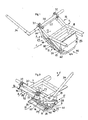
- the Fig. 1 to 6 relate to a closure device 1 for a crane silo for transporting pourable building materials such as concrete, gravel, sand or the like 3 and 4 illustrated container 3 of the crane silo 2, which is not shown, on a surface has ab nies support frame, has at an upper end a filling opening for a building material and at a funnel-like tapered lower end on a discharge opening for removal of the building material, wherein the container 3 at the upper end by hooks (not shown) is formed, where the crane silo by means of a crane, for example a tower crane, it can be raised and lowered by wire rope.
- a crane silo for transporting pourable building materials such as concrete, gravel, sand or the like 3 and 4 illustrated container 3 of the crane silo 2, which is not shown, on a surface has ab nies support frame, has at an upper end a filling opening for a building material and at a funnel-like tapered lower end on a discharge opening for removal of the building material, wherein the
- the downwardly tapering container may have a conical, truncated pyramidal shape of round or polygonal cross-section, for example, octagonal, after CH 685 831 A5 exhibit.
- the lever mechanism 6 acting on both sides of the closure device 1 closes manually or by motor or hydraulically / mechanically operable closure device 1, which is screwed by a flange connection to the lower container end or attached to the support frame of the crane silo 2.
- the closure device 1 serving as a guide of the discharged building material guide element 8, which adjoins the discharge opening 5 of the container 3 and preferably has a conically narrowing in the emptying cross-section, be it rectangular or round, adapted to the discharge opening, respectively.
- the guide element 8 formed as a guide or pipe socket forms part of the closure device 1, which responds to blocking the flow of a building material located in the container 3. for removing a building material from the container 3 with a tränslatorisch (rectilinear) back and forth adjustable slide plate 9 is formed, which in the closed position passes through the guide element 8 (approximately) transversely to the conveying flow of the building material.
- the slide plate 9 is guided at least outside of the guide element 8 and can protrude within the guide element 8 in laterally arranged to the direction of movement grooves 10 which are the tightness of the closure device 1 conducive, the grooves 10th not recommended for guiding the slide plate 9.
- the movements of the slide plate 9 by means of a lever 6 connected to the hand lever 11 or by a in the EP 2 465 655 A1 described hydraulic / mechanical actuator, for which a drive lever 31 ( Fig. 5 ) is provided and which will be described in more detail.
- the closing and at least partial opening of the conveying element 8 translationally movable back and forth slide plate 9 extends according to the illustrated embodiments in a sharp resp. obtuse angle to the flow or discharge direction F of the building material in the guide element 8 resp. the trained for the closure device 1 line section.
- movable slide plate 9 can by the oblique position in acute resp. obtuse angle reduces the acting of the building material on the slide plate 9 pressure and thereby the latter are moved with less force.
- slide plate 9 could also be guided exclusively in guide grooves on two opposing, preferably stationary inner walls of the conveying element, an embodiment that tends to wear and disturbances of the parts involved in the leadership.
- the baffle 8 could be part of the lower end of the container and built into the container shell, but would reduce the volume of container contents and create constructive circumstances. Such an embodiment is affected by the general inventive idea of this application, but not illustrated in the drawing.
- the slide plate 9 is guided in each case on the outer side 14, 15 of two spaced apart side walls 12, 13 of the guide element 8, whereby the side walls 12, 13 used for this purpose are advantageously arranged parallel and downstream of the conveying direction F of the building material.
- a guide of the slide plate 9 is one with the back on the outside 14, 15 of the side walls 12, 13 attached U-iron provided that a guideway 16, 17 resp. Guiding arrangement forms, which runs parallel to the direction of movement of the slide plate 9 and has at least twice the length of the movement path latter.
- the over the guide element 8 projecting guideways 16, 17 and the U-iron serving for this purpose are connected to their stability at the free-standing ends by a connecting element 52.
- the slide plate 9 is connected at the bottom with a guided in the guideways 16, 17 frame 18, each freely rotatably mounted guide roller 21, 22; 23, 24 (partially visible), which are mounted in pairs one behind the other on a connecting plate 25, 26 of the frame 18 and in the guideways 16, 17 are arranged.
- the connecting straps 25, 26 are in turn connected by a below the slide plate 9, the connecting straps 25, 26 connecting, transversely to the direction of movement of the slide plate 9 extending carrier 27, on which the slide plate 9 is attached.
- the frame 18 is respectively on both sides in the direction of movement resp. of the guide element 8 is connected to a lever mechanism 6, which consists of two identical drive components 28, 29, which are each assigned to a frame part or a connection tab 19, 20 for driving the frame 18.
- the lever mechanism 6 further consists of a on the freestanding ends of the guideways 16, 17 in bearing blocks 32, 33 rotatably mounted drive shaft 30, according to Fig. 5 and only indicated in this figure, has a firmly connected drive lever 31 for an above-mentioned actuator.
- the drive shaft 30 may also be mounted in bearing blocks connected to the support frame of the crane silo.
- the EP 2 465 655 described actuator is intended for a Krensilo, which is only suitable for a hose feeding a formwork.
- the actuating device is a dosing device acting on the delivery hose to form a delivery cross section on the delivery hose, formed by a with the opening movement, a gas for a preloaded closing movement of the metering device in a counter force to the opening movement to a closing pressure compressing hydraulic force.
- the hydraulic force used to move the slide plate 9 wherein the drive shaft 30 rotatably connected to the drive lever 31 with a piston-cylinder unit (not apparent) in two cylinder chambers dividing piston is drivingly connected and the one cylinder space of the cylinder of the piston-cylinder unit before or behind the piston for receiving a liquid medium with a fluid pump line connected and the cylinder chamber behind or in front of the piston connected to a counter pressure is, wherein the first and second cylinder space is conductively connected to a gas storage tank surrounding a separate pressure vessel.
- the actuating device could, for example, be fastened to the console elements 19, 20 projecting over the flange connection 7.
- a hand lever 34 is fixed to the drive shaft 30 of the lever mechanism 6, with which the slide plate 9 can be moved manually.
- a pivot lever 35, 36 is fixed to the drive shaft 30, the pivotal end of which is articulated at one end of a connected to the connecting plate 25, 26 of the frame 18 link 37, 38 the other end forming a joint.
- a hose attachment device 39 To attach a hanging attached conveyor hose (not shown) at the bottom of the guide element 8, a hose attachment device 39, respectively. Adaptation provided. This can be releasably attached and easily formed so that it can remain attached to the delivery hose after disassembly.
- hose fastening device 39 respectively.
- Adapting device for attaching different hose diameter resp. Tube cross-sections is formed and has a flow channel corresponding to the use of the crane silo, so that the fastening device 39 is also suitable for the processing of a conventional concrete mixture without delivery hose.
- the closure devices 1 shown in the figures are equipped for attachment of a hanging delivery hose (not shown).
- a detachable adapter frame 40 is provided, on which viewed in the conveying direction, a conically tapering on the conveyor tube cross-section guide member 41 is attached with a subsequent attachment ring 42 to which the delivery hose by means of a Bride (not visible) can be attached.
- the hose attachment resp. Adapting device 39 could also be designed for the purpose of supplying rigid concrete by a suitable, preferably adapted outlet opening, for example, with a short supply pipe, respectively. having hose.
- the hose fastening device 39 is formed on one side of the conveying element 8 with a suspension device 44 of two provided on the connecting frame 40 of the hose fastening device 39 ring hooks 45 and associated Aufstecknocken 46 and has opposite a pawl closure 47, which can be latched in each case by latches 48 on projecting lugs 49 on the guide element 8.
- the hose fastening device 39 has a handle 50 for mounting and dismounting the latter having auxiliary device 51st
- the Kransilo 2 could also be advantageously connected to the support frame deliverable outlet chute-as in the CH 685 831 A5 - Have to fill a to be charged from the side with concrete cavity.
Landscapes
- Engineering & Computer Science (AREA)
- Architecture (AREA)
- Mechanical Engineering (AREA)
- Civil Engineering (AREA)
- Structural Engineering (AREA)
- Filling Or Emptying Of Bunkers, Hoppers, And Tanks (AREA)
Priority Applications (1)
| Application Number | Priority Date | Filing Date | Title |
|---|---|---|---|
| EP13405059.0A EP2803784A1 (fr) | 2013-05-12 | 2013-05-12 | Silo de grue pour le transport de matériaux de construction granulaires, comme le béton, le gravier, le sable ou analogues |
Applications Claiming Priority (1)
| Application Number | Priority Date | Filing Date | Title |
|---|---|---|---|
| EP13405059.0A EP2803784A1 (fr) | 2013-05-12 | 2013-05-12 | Silo de grue pour le transport de matériaux de construction granulaires, comme le béton, le gravier, le sable ou analogues |
Publications (1)
| Publication Number | Publication Date |
|---|---|
| EP2803784A1 true EP2803784A1 (fr) | 2014-11-19 |
Family
ID=48576334
Family Applications (1)
| Application Number | Title | Priority Date | Filing Date |
|---|---|---|---|
| EP13405059.0A Withdrawn EP2803784A1 (fr) | 2013-05-12 | 2013-05-12 | Silo de grue pour le transport de matériaux de construction granulaires, comme le béton, le gravier, le sable ou analogues |
Country Status (1)
| Country | Link |
|---|---|
| EP (1) | EP2803784A1 (fr) |
Citations (9)
| Publication number | Priority date | Publication date | Assignee | Title |
|---|---|---|---|---|
| US3138117A (en) * | 1958-06-30 | 1964-06-23 | Entpr Railway Equipment Co | Sliding hopper closure housing outlet assembly |
| FR1494912A (fr) * | 1966-07-26 | 1967-09-15 | Perfectionnements aux bennes à béton | |
| CH685831A5 (de) | 1994-01-17 | 1995-10-13 | Eduard Voegtli | Einrichtung zum Transport von schüttfähigen Baumaterialien bzw. Baustoffen. |
| WO2004063112A2 (fr) * | 2003-01-13 | 2004-07-29 | Eitan Leibovitz | Systeme de liberation controlee d'un melange de ciment s'ecoulant d'une benne suspendue |
| EP1449984A1 (fr) * | 2003-02-21 | 2004-08-25 | Société d'Etude et Construction d'Application de la Tolerie "SECATOL" SA | Dispositif de vidage de benne à béton |
| DE20221458U1 (de) | 2002-12-23 | 2005-12-08 | Florian Eichinger Gmbh | Betonkübel mit schnell auswechselbarer Schüttgutleiteinrichtung |
| US20060073004A1 (en) * | 2004-09-24 | 2006-04-06 | Bak Saver, Llc, | Bucket apparatus |
| FR2905396A1 (fr) * | 2006-08-31 | 2008-03-07 | Secatol Soc Par Actions Simpli | Dispositif de vidage de benne a beton et benne a beton correspondante. |
| EP2465655A1 (fr) | 2010-12-18 | 2012-06-20 | Obrist Baugeräte AG | Procédé de vidage d'un silo de grue développé pour la réception et le transport suspendu de matériaux de construction coulants |
-
2013
- 2013-05-12 EP EP13405059.0A patent/EP2803784A1/fr not_active Withdrawn
Patent Citations (9)
| Publication number | Priority date | Publication date | Assignee | Title |
|---|---|---|---|---|
| US3138117A (en) * | 1958-06-30 | 1964-06-23 | Entpr Railway Equipment Co | Sliding hopper closure housing outlet assembly |
| FR1494912A (fr) * | 1966-07-26 | 1967-09-15 | Perfectionnements aux bennes à béton | |
| CH685831A5 (de) | 1994-01-17 | 1995-10-13 | Eduard Voegtli | Einrichtung zum Transport von schüttfähigen Baumaterialien bzw. Baustoffen. |
| DE20221458U1 (de) | 2002-12-23 | 2005-12-08 | Florian Eichinger Gmbh | Betonkübel mit schnell auswechselbarer Schüttgutleiteinrichtung |
| WO2004063112A2 (fr) * | 2003-01-13 | 2004-07-29 | Eitan Leibovitz | Systeme de liberation controlee d'un melange de ciment s'ecoulant d'une benne suspendue |
| EP1449984A1 (fr) * | 2003-02-21 | 2004-08-25 | Société d'Etude et Construction d'Application de la Tolerie "SECATOL" SA | Dispositif de vidage de benne à béton |
| US20060073004A1 (en) * | 2004-09-24 | 2006-04-06 | Bak Saver, Llc, | Bucket apparatus |
| FR2905396A1 (fr) * | 2006-08-31 | 2008-03-07 | Secatol Soc Par Actions Simpli | Dispositif de vidage de benne a beton et benne a beton correspondante. |
| EP2465655A1 (fr) | 2010-12-18 | 2012-06-20 | Obrist Baugeräte AG | Procédé de vidage d'un silo de grue développé pour la réception et le transport suspendu de matériaux de construction coulants |
Similar Documents
| Publication | Publication Date | Title |
|---|---|---|
| DE2162406C3 (de) | Schiebervorrichtung fur eine Pumpe mit zwei im Gegentakt arbeitenden Zylindern zum Fördern von Beton o.dgl | |
| DE2431840C3 (de) | Vorrichtung zur Materialentleerung aus einem Fülltrichter o.dgl. | |
| DE102016113140A1 (de) | Rüttleranordnung zum Herstellen von Stopfsäulen | |
| DE102008019995A1 (de) | Fahrzeug mit einem Mischbehälter | |
| EP2465655B1 (fr) | Procédé de vidage d'un silo de grue développé pour la réception et le transport suspendu de matériaux de construction coulants | |
| EP2535482B1 (fr) | Silo de grue pour le transport de matériaux de construction coulants, comme le béton, les graviers, le sable ou analogues | |
| DE2543379A1 (de) | Vorrichtung zur kontinuierlichen herstellung von angemachtem moertel | |
| DE19631312C2 (de) | Fahrbare Anlage zur Herstellung von Fließestrich | |
| DE8704215U1 (de) | Vorrichtung zum Transport und zur baustellenseitigen Bevorratung von schüttgutartigen Baustoffen | |
| EP2980334B1 (fr) | Silo de grue pour le transport et le traitement de matériaux de construction coulants | |
| EP1830017B1 (fr) | Benne pour le transport de matériaux de construction en vrac, comme béton, gravillons, sable | |
| EP2803784A1 (fr) | Silo de grue pour le transport de matériaux de construction granulaires, comme le béton, le gravier, le sable ou analogues | |
| DE19724504A1 (de) | Zweizylinderdickstoffpumpe | |
| DE10032459A1 (de) | Aus einem Schneckenverdichter und einem Preßbehälter Anordnung zur Aufnahme von zu verpressenden Abfallstoffen | |
| DE1227370B (de) | Beschickungsbehaelter fuer eine Betonbereitungs-anlage | |
| DE3240465C2 (de) | Vorrichtung zur Förderung von breiigen Massen, insbesondere Beton | |
| DE2142722A1 (de) | Pump- und Förderapparat für dichte Flüssigkeitsmischungen, wie Beton oder dgl | |
| DE2807046C3 (de) | Anlage zum Beschicken von Speicherbehältern mit Schüttgut | |
| DE102004009565B4 (de) | Vorrichtung zum Austragen von streufähigem Material | |
| DE10324715B4 (de) | Vorrichtung zum entmischungsfreien Zuführen von Feststoffen und Feststoffgemischen | |
| CH707015B1 (de) | Verfahren zum Befüllen einer Schalung mit Beton. | |
| DE20203463U1 (de) | Speicheranordnung zur vorübergehenden Aufnahme von zur Betonfertigung einsetzbarem pulverartigem Material, insbesondere Bindemittel | |
| DE1781145C3 (de) | Schrappbehälter für Setischrappervorrichtungen | |
| DE102006028580A1 (de) | Vorrichtung zur Auslaufdosierung eines Mischwerkes | |
| DE1531769C (de) | Müllstauvorrichtung an Müllfahrzeugen oder -anhängern |
Legal Events
| Date | Code | Title | Description |
|---|---|---|---|
| PUAI | Public reference made under article 153(3) epc to a published international application that has entered the european phase |
Free format text: ORIGINAL CODE: 0009012 |
|
| 17P | Request for examination filed |
Effective date: 20130512 |
|
| AK | Designated contracting states |
Kind code of ref document: A1 Designated state(s): AL AT BE BG CH CY CZ DE DK EE ES FI FR GB GR HR HU IE IS IT LI LT LU LV MC MK MT NL NO PL PT RO RS SE SI SK SM TR |
|
| AX | Request for extension of the european patent |
Extension state: BA ME |
|
| STAA | Information on the status of an ep patent application or granted ep patent |
Free format text: STATUS: THE APPLICATION IS DEEMED TO BE WITHDRAWN |
|
| 18D | Application deemed to be withdrawn |
Effective date: 20150520 |