EP2466573A2 - Eclairage - Google Patents
Eclairage Download PDFInfo
- Publication number
- EP2466573A2 EP2466573A2 EP11193695A EP11193695A EP2466573A2 EP 2466573 A2 EP2466573 A2 EP 2466573A2 EP 11193695 A EP11193695 A EP 11193695A EP 11193695 A EP11193695 A EP 11193695A EP 2466573 A2 EP2466573 A2 EP 2466573A2
- Authority
- EP
- European Patent Office
- Prior art keywords
- light
- guide plate
- emitting element
- light guide
- latching
- Prior art date
- Legal status (The legal status is an assumption and is not a legal conclusion. Google has not performed a legal analysis and makes no representation as to the accuracy of the status listed.)
- Granted
Links
Images



Classifications
-
- G—PHYSICS
- G09—EDUCATION; CRYPTOGRAPHY; DISPLAY; ADVERTISING; SEALS
- G09F—DISPLAYING; ADVERTISING; SIGNS; LABELS OR NAME-PLATES; SEALS
- G09F13/00—Illuminated signs; Luminous advertising
- G09F13/18—Edge-illuminated signs
-
- G—PHYSICS
- G08—SIGNALLING
- G08B—SIGNALLING SYSTEMS, e.g. PERSONAL CALLING SYSTEMS; ORDER TELEGRAPHS; ALARM SYSTEMS
- G08B7/00—Signalling systems according to two or more of groups G08B3/00 - G08B6/00
- G08B7/06—Signalling systems according to two or more of groups G08B3/00 - G08B6/00 using electric transmission, e.g. involving audible and visible signalling through the use of sound and light sources
- G08B7/062—Signalling systems according to two or more of groups G08B3/00 - G08B6/00 using electric transmission, e.g. involving audible and visible signalling through the use of sound and light sources indicating emergency exits
-
- G—PHYSICS
- G09—EDUCATION; CRYPTOGRAPHY; DISPLAY; ADVERTISING; SEALS
- G09F—DISPLAYING; ADVERTISING; SIGNS; LABELS OR NAME-PLATES; SEALS
- G09F13/00—Illuminated signs; Luminous advertising
- G09F13/20—Illuminated signs; Luminous advertising with luminescent surfaces or parts
- G09F13/22—Illuminated signs; Luminous advertising with luminescent surfaces or parts electroluminescent
-
- G—PHYSICS
- G09—EDUCATION; CRYPTOGRAPHY; DISPLAY; ADVERTISING; SEALS
- G09F—DISPLAYING; ADVERTISING; SIGNS; LABELS OR NAME-PLATES; SEALS
- G09F13/00—Illuminated signs; Luminous advertising
- G09F13/04—Signs, boards or panels, illuminated from behind the insignia
- G09F13/0418—Constructional details
- G09F2013/05—Constructional details indicating exit way or orientation
Definitions
- the invention relates to a luminaire with a luminaire housing, a luminous element, a light guide plate and a light emitting element according to the preamble in claim 1.
- the light-emitting element is provided with a corresponding icon, which appears backlit accordingly during operation of the lamp.
- the luminaire housing forms a frame which serves, inter alia, for holding the light-emitting element.
- the frame is seen as a boundary of the light-emitting element. Due to the design of the frame, the design possibilities of the lamp are limited with respect to the external appearance.
- the invention has for its object to provide a corresponding improved luminaire;
- a corresponding lamp with improved design options should be specified.
- a luminaire which has a luminaire housing, a luminous element and a light guide plate with a narrow side and a flat side, wherein the luminous element and the light guide are designed and arranged in the luminaire housing, that emitted by the luminous element light in the Lichtleitplatte enters via the narrow side and emerges from the light guide plate on the flat side; Furthermore, the lamp has a light emitting element with a light emitting surface through which a surface normal is fixed, wherein the light emitting element is designed and arranged such that the from the flat side of the Lichtleitplatte emerging light leaves the lamp in the direction of the surface normal on the light emitting surface of the light emitting element.
- the light-emitting element has a latching element for a latching connection with the luminaire housing, wherein, viewed in a projection along the surface normal, the latching element is arranged completely within the area circumscribed by the light-emitting surface.
- the light-emitting element can be supported on the luminaire housing without the need for a frame element around the light-emitting surface.
- the light-emitting element can be particularly easy to connect to the light housing due to the locking connection.
- the light-emitting element preferably has an inner surface lying opposite the light-emitting surface, wherein the latching element is arranged projecting from the inner surface.
- the locking element is arranged at a distance from a lateral boundary of the inner surface.
- the light guide plate there is a further distance between the light guide plate and the inner surface of the light emitting element;
- This further distance is advantageously between 1 mm and 20 mm, more preferably between 3 mm and 10 mm.
- the narrow side of the light guide plate with respect to the light emission surface can be arranged offset inwardly in the projection along the surface normal, such that the luminous element does not protrude beyond the area circumscribed by the light emission surface.
- a particularly compact design of the lamp is further supported.
- the lamp also has a reflector element which, comprising the light guide plate, is arranged on the light-emitting element.
- a reflector element which, comprising the light guide plate, is arranged on the light-emitting element.
- the light-emitting element expediently has a second latching element which is part of the second latching connection.
- the reflector element preferably further has a recess through which the second latching element extends.
- the lamp further advantageously has a sealing element, which is sealingly arranged between the light-emitting element and the lamp housing. If the reflector element is mounted on the light-emitting element, a stiffening of the light-emitting element can be achieved, which has an advantageous effect on the action of the sealing element.
- the reflector element has a passage opening or a recess, wherein the latching element is arranged to extend through the passage opening or through the recess.
- the reflector element can be formed such that it extends at least substantially in a circumferential manner to the outer edge region of the inner surface of the light emitting element, whereby light can be directed particularly effectively to this edge region. In this way it can be achieved that also the edge region of the light emission surface appears to be particularly well illuminated.
- the reflector element preferably has a light passage opening which is arranged such that the light emitted by the luminous element passes through the light passage opening before it enters the light guide plate via its narrow side. This further increases the efficiency of the luminaire.
- the reflector element has a surface area extending between the light-guiding plate and the light-emitting element, which is designed to be divergently shaped in the direction of the light-emitting element, the reflector element makes it possible to light particularly effectively into the edge area of the inner surface of the light-emitting element Steer light emitting element and thus promote a particularly good illumination of the edge region of the light emitting surface.
- the light guide plate further comprises a further flat side, which is arranged opposite the first flat side opposite, wherein the reflector element is arranged such that it directly and preferably flat to the other flat side borders.
- the light-emitting element is preferably made of plastic and is advantageously designed as an injection molded part.
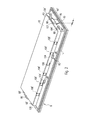
- Fig. 1 is a perspective sketch of a lamp according to the embodiment shown.
- the luminaire has a luminaire housing 2 and an at least partially translucent light-emitting element 8, which preferably consists of plastic and is designed, for example, as an injection-molded part.
- Fig. 1 These two components are shown separately from each other to represent a view into the luminaire housing 2. In the state provided for the operation, however, the light-emitting element 8 is connected to the lamp housing 2, as indicated by the two long arrows in Fig. 1 indicated.
- the luminaire housing 2 can in particular be trough-shaped, for example cuboidal or box-shaped, designed such that an interior region I of the luminaire is thereby fixed. Furthermore, a light exit opening 22 can be defined by the luminaire housing 2, wherein the light output element 8 is provided for being connected to the luminaire housing 2 in such a way that it covers the light exit opening 22 in the state of the luminaire intended for operation.
- the luminaire has a luminous element 4, which comprises, for example, a circuit board, on which an LED 42 is arranged, and preferably also a plurality of further LEDs 42 'are arranged.
- the lighting element 4, as in Fig. 1 shown, for example, between three and ten LEDs 42, 42 ', which are arranged along a straight line.
- the straight line can be oriented parallel to an edge region of the light exit opening 22.
- the luminous element 4 can furthermore be arranged in particular in the inner region I of the luminaire.
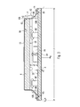
- Fig. 2 is a perspective sketch of the detached from the lamp housing 2 light emitting element 8 shown from a different angle and in Fig. 3 a corresponding cross-section.
- the luminaire furthermore has a light guide plate 6 with a narrow side 62 and a flat side 64.
- a light guide plate 6 with a narrow side 62 and a flat side 64.
- flat side Let one of the two given by the plate shape, plan and parallel to each other, large surface areas referred to, with “narrow side” a surface area of the two large surface areas laterally connects, so to speak, a lateral edge region of the plate.
- the light-emitting element 8 has a light-emitting surface 84, by means of which a surface normal N is defined.
- the light emission surface 84 may be a surface region of the light emission element 8 that is planar at least in a first approximation.
- the light guide plate 6 is designed and arranged in the luminaire housing 2 such that a light emitted by the luminous element 4 enters the light guide plate 6 via its narrow side 62 and exits from the light guide plate 6 via its flat side 64.
- the light guide plate 6 may be provided in particular with structures, via which the light is coupled in the direction of the light-emitting element 8.
- the arrangement is such that this light in its further course leaves the luminaire in the direction of the surface normal N via the light emission surface 84 of the light-emitting element 8.
- the light emitting surface 84 may include or consist of a pictogram, so that this icon is accordingly interspersed with activated light element 4 of the light.
- the lamp results in viewing the lamp in a projection along the surface normal N, circumscribed by the light emitting surface 84 area B.
- the area B thus corresponds to the projected light emitting surface 84.
- the light housing 2 is shaped such that it, in this Projection is completely within this B area.
- the light guide plate 6 is formed so that it lies completely within the area B, that is, as viewed "smaller" than the light emitting element eighth
- the light-emitting element 8 further includes, in the Figures 2 and 3 designated latching element 86 for a latching connection R1 with the lamp housing 2.
- the latching element 86 is disposed completely within the region B circumscribed by the light emitting surface 84.
- the latching element 86 can be introduced through the light outlet opening 22 into the interior region I of the luminaire and be brought there to produce the latching connection R1 with a corresponding counter-latching element 24.
- the described latching connection R1 makes it possible, in particular, to hold the light-emitting element 8 on the luminaire housing 2 without having to provide a frame element around the light-emitting surface 84. In this way, in particular the design possibilities of the lamp are improved with respect to their external appearance.
- the light-emitting element 8 can furthermore have an inner surface 81 opposite the light-emitting surface 84, wherein the latching element 86 is arranged so as to protrude from the inner surface 81.
- the locking element 86 is accordingly arranged completely in the inner region I of the luminaire in this embodiment.
- the inner surface 81 may be designed plan, at least in a first approximation; Preferably, it is provided with a structure which serves a further scattering, equalization or lighting optimization.
- this further distance a2 is advantageously between 1 mm and 20 mm, more preferably between 3 mm and 10 mm, for example between 6 mm and 7 mm.
- the narrow side 62 of the light guide plate 6, viewed in the projection parallel to the surface normal N can be arranged within the region B that is separated from the light emission surface 84 is circumscribed.
- the light-emitting element 4 does not carry, as it were, laterally, but instead finds space "behind" the light-emitting element 8. This makes the lamp very compact.
- the lamp also has a reflector element 10, which is arranged on the light-emitting element 8 comprising the light guide plate 6.
- the reflector element 10 supports a particularly effective use of a light emitted by the luminous element 4.
- the reflector element 10 the light can be directed particularly uniformly on the inner surface 81 of the light-emitting element 8, thereby further enabling a particularly uniform illumination of the light-emitting surface 84.
- the reflector element 10 extends - as from a synopsis of Figures 2 and 3 Suggestively emerges - arranged in such an area between the luminous element 4 and the inner surface 81 of the light emitting element 8 that no light from the luminous element 4 can reach the inner surface 81 directly.
- the light-emitting element 4 or its light-emitting surface areas are therefore, as it were, shaded by the reflector element 10 when viewing the light-emitting surface 84.
- the reflector element 10 is supported on the light-emitting element 8 via a second latching connection R2 .
- the light-emitting element 8 expediently has a second latching element 88, which is part of the second latching connection R2 , wherein the second latching element 88 advantageously protrudes from the inner surface 81 of the light-emitting element 8, as does the first-mentioned latching element 86, and in particular is spaced from its lateral boundary 83 is arranged.
- the reflector element 10 preferably has a, in Fig. 2 Exemplarily designated, recess 104, through which the second latching element 88 extends. This makes it possible to effect a reliable mounting of the reflector element 10 on the light-emitting element 8, wherein a uniform illumination of the inner surface 81 of the light-emitting element 8 is at most marginally impaired by the second latching connection R 2.
- a sealing element 14 may be provided which is sealingly arranged between the light-emitting element 8 and the lamp housing 2, in particular annularly closed.
- a stiffening of the light-emitting element 8 can be achieved, which has an advantageous effect on the sealing effect of the sealing element 14 8.
- the reflector element 10 furthermore has a, in Fig. 2 Exemplarily designated, passage opening 102 or alternatively a (not shown in the figures) indentation, wherein the locking element 86 is arranged for the first-mentioned locking connection R1 between the light emitting element 8 and the lamp housing 2 through the passage opening 102 and extending through the recess therethrough ,
- the reflector element 10 can be formed in such a way that it extends substantially as far as the outer edge region of the inner surface 81, as a result of which light can be directed particularly effectively to this edge region. In this way it can be achieved that also the edge region of the light emission surface 84 appears to be particularly well illuminated.
- the embodiment in the form of the passage opening 102 is more advantageous than the embodiment in the form of the indentation, as in the case of the passage opening 102, the reflector element 10 may be annularly formed engaging in the groove 85, whereby in particular the said stiffening of the light emitting element 8 is better supported.
- the reflector element 10 advantageously has a light passage opening 106 which is arranged such that the light emitted by the luminous element 4 or by the light emitting diode 42 passes through the light passage opening 106 before it enters the light guide plate 6 via its narrow side 62. This makes it possible - in comparison to a corresponding recess - the photometrically effective surface of Make reflector element 10 is particularly large, so that overall the effect of the reflector element 10 is improved.
- a particularly good light control to the edge region of the inner surface 81 of the light emitting element 8 can be achieved if the reflector element 10 has a surface region 108 which extends between the light guide plate 6 and the light emitting element 8 and which, in the direction of the light emitting element 8 to divergently shaped is.
- the surface area 108 is annularly closed, so that the reflector element 10 has a circumferential "chamfer" or a funnel shape.
- the embodiment may be such that the surface area 108 engages directly in the groove 85.
- the surface area 108 is configured such that, viewed in the projection parallel to the surface normal N , it extends exclusively or at least more than 90%, outside the projection of the flat side 64 of the light guide plate 6.
- the configuration is furthermore advantageous such that the imaginary continuation or extension of the area 108 passes through approximately the lateral boundary of the light emission area 84, for example deviates at most by a small distance s from the latter, wherein the small distance s is preferably smaller than one Strength d, more preferably less than half the thickness d of the light-emitting element 8 between the light-emitting surface 84 and the inner surface 81.
- a further latching connection R3 is furthermore preferably provided.
- the light guide plate 6 may have a protruding pin 68 which - as in Fig. 2 shown - engages in a corresponding receiving opening in the reflector element 10.
- the further latching connection R 3 is designed such that the light guide plate 6 can be arranged as intended without the aid of a tool on the reflector element 10.
- the light guide plate 6 may have a further flat side 66, which is arranged opposite the first-mentioned flat side 64, wherein the reflector element 10 is arranged such that it directly and thereby preferably flat adjacent to the other flat side 66.
- the reflector element 10 may be shaped such that it also flatly contacts the narrow side 62 and / or all other narrow sides of the light guide plate 6, so that the reflector element 10, so to speak, conforms to the light guide plate 6. This is advantageous with respect to the efficiency of the luminaire.
- Fig. 4 an exploded view of light emitting element 8, reflector element 10 and light guide plate 8 is shown.
- a pictogram is shown by way of example, with which the light-emitting element 8 can be provided, so that, as a result, at least partially, the light-emitting surface 84 is formed.
- the sealing element 14 is located.
- components of the lamp can be about the snap-in connections described R2 and R3 and optionally via an adhesive bond for holding the seal member 14 to the light emitting element 8 to form a unit, which - as shown by the two long arrows in Fig. 1 indicated - in an assembly step as a whole with the lamp housing 2 can be connected via the first-mentioned latching connection R1 , so that it is alone thereby supported as a whole on the lamp housing 2.
- the first latching connection R1 can also have at least one further latching element 86 'and at least one further corresponding latching element, wherein these at least two elements are designed analogously to the first mentioned corresponding elements 86, 24.
- the second latching connection R2 for holding the reflector element 10 on the light-emitting element 8 can have at least one further second latching element 88 'and at least one corresponding further cut-out 104' in the reflector element 10, each formed analogously to the first-mentioned second reflector element 88 and the recess 104 are. This also contributes to the further stiffening of the light-emitting element 8.
- one or more further light passage openings 106 ' may be formed in the reflector element 10 for each of the further LEDs 42', so that in particular a corresponding light passage opening 106, 106 'is provided for each of the LEDs 42, 42'.
- the further latching connection R3 between the light guide plate 6 and the reflector element 10 may include a plurality of pins 68 'and a plurality of associated receiving openings, whereby the holder of the light guide plate 6 can be further improved on the reflector element 10.
- the luminaire described so far is suitable as a surface-mounted luminaire.
- Fig. 5 a variant of the lamp is shown, which is designed as a recessed luminaire.
Landscapes
- Physics & Mathematics (AREA)
- General Physics & Mathematics (AREA)
- Engineering & Computer Science (AREA)
- Theoretical Computer Science (AREA)
- Business, Economics & Management (AREA)
- Emergency Management (AREA)
- Non-Portable Lighting Devices Or Systems Thereof (AREA)
- Planar Illumination Modules (AREA)
Applications Claiming Priority (1)
| Application Number | Priority Date | Filing Date | Title |
|---|---|---|---|
| DE102010063272A DE102010063272A1 (de) | 2010-12-16 | 2010-12-16 | Leuchte |
Publications (3)
| Publication Number | Publication Date |
|---|---|
| EP2466573A2 true EP2466573A2 (fr) | 2012-06-20 |
| EP2466573A3 EP2466573A3 (fr) | 2012-10-17 |
| EP2466573B1 EP2466573B1 (fr) | 2014-04-02 |
Family
ID=45442861
Family Applications (1)
| Application Number | Title | Priority Date | Filing Date |
|---|---|---|---|
| EP11193695.1A Active EP2466573B1 (fr) | 2010-12-16 | 2011-12-15 | Eclairage |
Country Status (2)
| Country | Link |
|---|---|
| EP (1) | EP2466573B1 (fr) |
| DE (1) | DE102010063272A1 (fr) |
Cited By (1)
| Publication number | Priority date | Publication date | Assignee | Title |
|---|---|---|---|---|
| FR2995660A1 (fr) * | 2012-09-14 | 2014-03-21 | Emerson Network Power Ind Systems | Luminaire de securite encastre |
Families Citing this family (1)
| Publication number | Priority date | Publication date | Assignee | Title |
|---|---|---|---|---|
| DE202012104101U1 (de) | 2012-10-25 | 2014-01-30 | Zumtobel Lighting Gmbh | Lichtabgabeelement für eine Leuchte, sowie Leuchte mit einem Lichtabgabeelement |
Citations (1)
| Publication number | Priority date | Publication date | Assignee | Title |
|---|---|---|---|---|
| DE202006014352U1 (de) | 2006-04-13 | 2007-01-11 | Zumtobel Lighting Gmbh | Leuchte mit wenigstens einer lichtdurchlässigen Abdeckung |
Family Cites Families (7)
| Publication number | Priority date | Publication date | Assignee | Title |
|---|---|---|---|---|
| DE19709529A1 (de) * | 1997-03-10 | 1998-09-24 | Grunwald Hans Dieter | Display für Werbe- und Hinweis-Aussagen |
| JP3743270B2 (ja) * | 2000-07-12 | 2006-02-08 | 松下電工株式会社 | 表示用照明器具 |
| GB2376287A (en) * | 2001-05-18 | 2002-12-11 | Michael Gulvin Russell | Luminous tile |
| DE102004012541A1 (de) * | 2004-03-15 | 2005-10-06 | BSH Bosch und Siemens Hausgeräte GmbH | Leuchtmodul zur Montage in einem Haushaltgerät und Haushaltgerät mit einem solchen |
| JP4413668B2 (ja) * | 2004-03-23 | 2010-02-10 | 日本ライツ株式会社 | 導光板および光源装置ならびに平面発光装置 |
| GB2450683A (en) * | 2007-06-27 | 2009-01-07 | Teamwin Opto Electronics Co Lt | Multi-functional LED lamp |
| DE202010001814U1 (de) * | 2010-02-03 | 2010-06-02 | Kusanke Einrichtungen Gmbh & Co. Kg | Lichtfeld |
-
2010
- 2010-12-16 DE DE102010063272A patent/DE102010063272A1/de not_active Withdrawn
-
2011
- 2011-12-15 EP EP11193695.1A patent/EP2466573B1/fr active Active
Patent Citations (1)
| Publication number | Priority date | Publication date | Assignee | Title |
|---|---|---|---|---|
| DE202006014352U1 (de) | 2006-04-13 | 2007-01-11 | Zumtobel Lighting Gmbh | Leuchte mit wenigstens einer lichtdurchlässigen Abdeckung |
Cited By (1)
| Publication number | Priority date | Publication date | Assignee | Title |
|---|---|---|---|---|
| FR2995660A1 (fr) * | 2012-09-14 | 2014-03-21 | Emerson Network Power Ind Systems | Luminaire de securite encastre |
Also Published As
| Publication number | Publication date |
|---|---|
| EP2466573A3 (fr) | 2012-10-17 |
| EP2466573B1 (fr) | 2014-04-02 |
| DE102010063272A1 (de) | 2012-06-21 |
Similar Documents
| Publication | Publication Date | Title |
|---|---|---|
| EP2979288B1 (fr) | Module de touche pour une touche de clavier et procédé de fabrication d'un module de touche pour une touche de clavier | |
| EP2151899B1 (fr) | Système de bande lumineuse | |
| EP3320259A1 (fr) | Lampe pour former une ligne lumineuse | |
| EP3727073B1 (fr) | Boucle de ceinture éclairée pour système de ceinture de sécurité d'un véhicule automobile | |
| DE202012101239U1 (de) | Abdeckung für ein Leuchtengehäuse | |
| EP2796770A1 (fr) | Éclairage doté d'une unité de production de lumière et d'un élément de cadre | |
| WO2015132177A1 (fr) | Luminaire ou ensemble lumineux comprenant un élément support allongé et un module lumineux fixé de manière libérable | |
| EP2466573B1 (fr) | Eclairage | |
| EP2711750B1 (fr) | Lampe à DEL dotée d'une plaque de guide d'ondes optiques | |
| DE202011051503U1 (de) | Lichtleitaufbau und Scheinwerfer für ein Fahrzeug | |
| EP4034807B1 (fr) | Luminaire ayant une région pour émettre de la lumière sur une surface | |
| DE202014104801U1 (de) | Längliche LED-Leuchte | |
| EP2142392A1 (fr) | Pare-soleil pour véhicule automobile | |
| EP3814172B1 (fr) | Procédé de fabrication d'un module de clignotant ainsi que module de clignotant, système de rétroviseur et véhicule automobile | |
| WO2017102401A1 (fr) | Dispositif d'éclairage pour un véhicule | |
| EP2175188B1 (fr) | Eclairage | |
| DE102023132212B3 (de) | Mehrteiliger Gehäusekörper | |
| DE10315771A1 (de) | Leuchte mit geschlossener Lichtabstrahlfläche | |
| EP4297003B1 (fr) | Lampe de signalisation de secours dotée d'un éclairage de voie de secours supplémentaire | |
| EP3557124A1 (fr) | Luminaire à del plate | |
| EP2711622B1 (fr) | Lampe dotée d'une protection contre le contact | |
| EP4589575A1 (fr) | Feu de signalisation de sécurité | |
| DE102004051315A1 (de) | Kennzeichenleuchte für ein Kraftfahrzeug | |
| EP4484221A1 (fr) | Dispositif d'éclairage pour l'éclairage de l'habitacle d'un véhicule | |
| DE102021105928A1 (de) | Akustisch optische Warneinrichtung, insbesondere für Einsatzfahrzeuge |
Legal Events
| Date | Code | Title | Description |
|---|---|---|---|
| PUAI | Public reference made under article 153(3) epc to a published international application that has entered the european phase |
Free format text: ORIGINAL CODE: 0009012 |
|
| AK | Designated contracting states |
Kind code of ref document: A2 Designated state(s): AL AT BE BG CH CY CZ DE DK EE ES FI FR GB GR HR HU IE IS IT LI LT LU LV MC MK MT NL NO PL PT RO RS SE SI SK SM TR |
|
| AX | Request for extension of the european patent |
Extension state: BA ME |
|
| PUAL | Search report despatched |
Free format text: ORIGINAL CODE: 0009013 |
|
| AK | Designated contracting states |
Kind code of ref document: A3 Designated state(s): AL AT BE BG CH CY CZ DE DK EE ES FI FR GB GR HR HU IE IS IT LI LT LU LV MC MK MT NL NO PL PT RO RS SE SI SK SM TR |
|
| AX | Request for extension of the european patent |
Extension state: BA ME |
|
| RIC1 | Information provided on ipc code assigned before grant |
Ipc: G09F 13/18 20060101AFI20120912BHEP Ipc: G09F 13/22 20060101ALI20120912BHEP Ipc: G09F 13/04 20060101ALN20120912BHEP |
|
| 17P | Request for examination filed |
Effective date: 20130328 |
|
| RIC1 | Information provided on ipc code assigned before grant |
Ipc: G09F 13/22 20060101ALI20130717BHEP Ipc: G09F 13/18 20060101AFI20130717BHEP Ipc: G09F 13/04 20060101ALN20130717BHEP |
|
| GRAP | Despatch of communication of intention to grant a patent |
Free format text: ORIGINAL CODE: EPIDOSNIGR1 |
|
| INTG | Intention to grant announced |
Effective date: 20131108 |
|
| GRAS | Grant fee paid |
Free format text: ORIGINAL CODE: EPIDOSNIGR3 |
|
| GRAA | (expected) grant |
Free format text: ORIGINAL CODE: 0009210 |
|
| AK | Designated contracting states |
Kind code of ref document: B1 Designated state(s): AL AT BE BG CH CY CZ DE DK EE ES FI FR GB GR HR HU IE IS IT LI LT LU LV MC MK MT NL NO PL PT RO RS SE SI SK SM TR |
|
| REG | Reference to a national code |
Ref country code: GB Ref legal event code: FG4D Free format text: NOT ENGLISH |
|
| REG | Reference to a national code |
Ref country code: CH Ref legal event code: EP Ref country code: AT Ref legal event code: REF Ref document number: 660529 Country of ref document: AT Kind code of ref document: T Effective date: 20140415 Ref country code: CH Ref legal event code: NV Representative=s name: FIAMMENGHI-FIAMMENGHI, CH |
|
| REG | Reference to a national code |
Ref country code: IE Ref legal event code: FG4D Free format text: LANGUAGE OF EP DOCUMENT: GERMAN |
|
| REG | Reference to a national code |
Ref country code: DE Ref legal event code: R096 Ref document number: 502011002591 Country of ref document: DE Effective date: 20140515 |
|
| REG | Reference to a national code |
Ref country code: NL Ref legal event code: VDEP Effective date: 20140402 |
|
| REG | Reference to a national code |
Ref country code: LT Ref legal event code: MG4D |
|
| PG25 | Lapsed in a contracting state [announced via postgrant information from national office to epo] |
Ref country code: FI Free format text: LAPSE BECAUSE OF FAILURE TO SUBMIT A TRANSLATION OF THE DESCRIPTION OR TO PAY THE FEE WITHIN THE PRESCRIBED TIME-LIMIT Effective date: 20140402 Ref country code: NO Free format text: LAPSE BECAUSE OF FAILURE TO SUBMIT A TRANSLATION OF THE DESCRIPTION OR TO PAY THE FEE WITHIN THE PRESCRIBED TIME-LIMIT Effective date: 20140702 Ref country code: CZ Free format text: LAPSE BECAUSE OF FAILURE TO SUBMIT A TRANSLATION OF THE DESCRIPTION OR TO PAY THE FEE WITHIN THE PRESCRIBED TIME-LIMIT Effective date: 20140402 Ref country code: BG Free format text: LAPSE BECAUSE OF FAILURE TO SUBMIT A TRANSLATION OF THE DESCRIPTION OR TO PAY THE FEE WITHIN THE PRESCRIBED TIME-LIMIT Effective date: 20140702 Ref country code: NL Free format text: LAPSE BECAUSE OF FAILURE TO SUBMIT A TRANSLATION OF THE DESCRIPTION OR TO PAY THE FEE WITHIN THE PRESCRIBED TIME-LIMIT Effective date: 20140402 Ref country code: GR Free format text: LAPSE BECAUSE OF FAILURE TO SUBMIT A TRANSLATION OF THE DESCRIPTION OR TO PAY THE FEE WITHIN THE PRESCRIBED TIME-LIMIT Effective date: 20140703 Ref country code: IS Free format text: LAPSE BECAUSE OF FAILURE TO SUBMIT A TRANSLATION OF THE DESCRIPTION OR TO PAY THE FEE WITHIN THE PRESCRIBED TIME-LIMIT Effective date: 20140802 Ref country code: CY Free format text: LAPSE BECAUSE OF FAILURE TO SUBMIT A TRANSLATION OF THE DESCRIPTION OR TO PAY THE FEE WITHIN THE PRESCRIBED TIME-LIMIT Effective date: 20140402 Ref country code: LT Free format text: LAPSE BECAUSE OF FAILURE TO SUBMIT A TRANSLATION OF THE DESCRIPTION OR TO PAY THE FEE WITHIN THE PRESCRIBED TIME-LIMIT Effective date: 20140402 |
|
| PG25 | Lapsed in a contracting state [announced via postgrant information from national office to epo] |
Ref country code: SE Free format text: LAPSE BECAUSE OF FAILURE TO SUBMIT A TRANSLATION OF THE DESCRIPTION OR TO PAY THE FEE WITHIN THE PRESCRIBED TIME-LIMIT Effective date: 20140402 Ref country code: RS Free format text: LAPSE BECAUSE OF FAILURE TO SUBMIT A TRANSLATION OF THE DESCRIPTION OR TO PAY THE FEE WITHIN THE PRESCRIBED TIME-LIMIT Effective date: 20140402 Ref country code: LV Free format text: LAPSE BECAUSE OF FAILURE TO SUBMIT A TRANSLATION OF THE DESCRIPTION OR TO PAY THE FEE WITHIN THE PRESCRIBED TIME-LIMIT Effective date: 20140402 Ref country code: PL Free format text: LAPSE BECAUSE OF FAILURE TO SUBMIT A TRANSLATION OF THE DESCRIPTION OR TO PAY THE FEE WITHIN THE PRESCRIBED TIME-LIMIT Effective date: 20140402 Ref country code: ES Free format text: LAPSE BECAUSE OF FAILURE TO SUBMIT A TRANSLATION OF THE DESCRIPTION OR TO PAY THE FEE WITHIN THE PRESCRIBED TIME-LIMIT Effective date: 20140402 Ref country code: HR Free format text: LAPSE BECAUSE OF FAILURE TO SUBMIT A TRANSLATION OF THE DESCRIPTION OR TO PAY THE FEE WITHIN THE PRESCRIBED TIME-LIMIT Effective date: 20140402 |
|
| PG25 | Lapsed in a contracting state [announced via postgrant information from national office to epo] |
Ref country code: PT Free format text: LAPSE BECAUSE OF FAILURE TO SUBMIT A TRANSLATION OF THE DESCRIPTION OR TO PAY THE FEE WITHIN THE PRESCRIBED TIME-LIMIT Effective date: 20140804 |
|
| REG | Reference to a national code |
Ref country code: DE Ref legal event code: R097 Ref document number: 502011002591 Country of ref document: DE |
|
| PG25 | Lapsed in a contracting state [announced via postgrant information from national office to epo] |
Ref country code: EE Free format text: LAPSE BECAUSE OF FAILURE TO SUBMIT A TRANSLATION OF THE DESCRIPTION OR TO PAY THE FEE WITHIN THE PRESCRIBED TIME-LIMIT Effective date: 20140402 Ref country code: DK Free format text: LAPSE BECAUSE OF FAILURE TO SUBMIT A TRANSLATION OF THE DESCRIPTION OR TO PAY THE FEE WITHIN THE PRESCRIBED TIME-LIMIT Effective date: 20140402 Ref country code: RO Free format text: LAPSE BECAUSE OF FAILURE TO SUBMIT A TRANSLATION OF THE DESCRIPTION OR TO PAY THE FEE WITHIN THE PRESCRIBED TIME-LIMIT Effective date: 20140402 Ref country code: SK Free format text: LAPSE BECAUSE OF FAILURE TO SUBMIT A TRANSLATION OF THE DESCRIPTION OR TO PAY THE FEE WITHIN THE PRESCRIBED TIME-LIMIT Effective date: 20140402 |
|
| PLBE | No opposition filed within time limit |
Free format text: ORIGINAL CODE: 0009261 |
|
| STAA | Information on the status of an ep patent application or granted ep patent |
Free format text: STATUS: NO OPPOSITION FILED WITHIN TIME LIMIT |
|
| 26N | No opposition filed |
Effective date: 20150106 |
|
| PG25 | Lapsed in a contracting state [announced via postgrant information from national office to epo] |
Ref country code: IT Free format text: LAPSE BECAUSE OF FAILURE TO SUBMIT A TRANSLATION OF THE DESCRIPTION OR TO PAY THE FEE WITHIN THE PRESCRIBED TIME-LIMIT Effective date: 20140402 |
|
| REG | Reference to a national code |
Ref country code: DE Ref legal event code: R097 Ref document number: 502011002591 Country of ref document: DE Effective date: 20150106 |
|
| PG25 | Lapsed in a contracting state [announced via postgrant information from national office to epo] |
Ref country code: RS Free format text: LAPSE BECAUSE OF FAILURE TO SUBMIT A TRANSLATION OF THE DESCRIPTION OR TO PAY THE FEE WITHIN THE PRESCRIBED TIME-LIMIT Effective date: 20141119 |
|
| PG25 | Lapsed in a contracting state [announced via postgrant information from national office to epo] |
Ref country code: BE Free format text: LAPSE BECAUSE OF NON-PAYMENT OF DUE FEES Effective date: 20141231 |
|
| PG25 | Lapsed in a contracting state [announced via postgrant information from national office to epo] |
Ref country code: SI Free format text: LAPSE BECAUSE OF FAILURE TO SUBMIT A TRANSLATION OF THE DESCRIPTION OR TO PAY THE FEE WITHIN THE PRESCRIBED TIME-LIMIT Effective date: 20140402 Ref country code: LU Free format text: LAPSE BECAUSE OF FAILURE TO SUBMIT A TRANSLATION OF THE DESCRIPTION OR TO PAY THE FEE WITHIN THE PRESCRIBED TIME-LIMIT Effective date: 20141215 |
|
| REG | Reference to a national code |
Ref country code: IE Ref legal event code: MM4A |
|
| PG25 | Lapsed in a contracting state [announced via postgrant information from national office to epo] |
Ref country code: IE Free format text: LAPSE BECAUSE OF NON-PAYMENT OF DUE FEES Effective date: 20141215 |
|
| REG | Reference to a national code |
Ref country code: FR Ref legal event code: PLFP Year of fee payment: 5 |
|
| PG25 | Lapsed in a contracting state [announced via postgrant information from national office to epo] |
Ref country code: SM Free format text: LAPSE BECAUSE OF FAILURE TO SUBMIT A TRANSLATION OF THE DESCRIPTION OR TO PAY THE FEE WITHIN THE PRESCRIBED TIME-LIMIT Effective date: 20140402 |
|
| PG25 | Lapsed in a contracting state [announced via postgrant information from national office to epo] |
Ref country code: MC Free format text: LAPSE BECAUSE OF FAILURE TO SUBMIT A TRANSLATION OF THE DESCRIPTION OR TO PAY THE FEE WITHIN THE PRESCRIBED TIME-LIMIT Effective date: 20140402 |
|
| PG25 | Lapsed in a contracting state [announced via postgrant information from national office to epo] |
Ref country code: TR Free format text: LAPSE BECAUSE OF FAILURE TO SUBMIT A TRANSLATION OF THE DESCRIPTION OR TO PAY THE FEE WITHIN THE PRESCRIBED TIME-LIMIT Effective date: 20140402 Ref country code: HU Free format text: LAPSE BECAUSE OF FAILURE TO SUBMIT A TRANSLATION OF THE DESCRIPTION OR TO PAY THE FEE WITHIN THE PRESCRIBED TIME-LIMIT; INVALID AB INITIO Effective date: 20111215 Ref country code: MT Free format text: LAPSE BECAUSE OF FAILURE TO SUBMIT A TRANSLATION OF THE DESCRIPTION OR TO PAY THE FEE WITHIN THE PRESCRIBED TIME-LIMIT Effective date: 20140402 |
|
| REG | Reference to a national code |
Ref country code: FR Ref legal event code: PLFP Year of fee payment: 6 |
|
| REG | Reference to a national code |
Ref country code: FR Ref legal event code: PLFP Year of fee payment: 7 |
|
| PG25 | Lapsed in a contracting state [announced via postgrant information from national office to epo] |
Ref country code: MK Free format text: LAPSE BECAUSE OF FAILURE TO SUBMIT A TRANSLATION OF THE DESCRIPTION OR TO PAY THE FEE WITHIN THE PRESCRIBED TIME-LIMIT Effective date: 20140402 |
|
| REG | Reference to a national code |
Ref country code: DE Ref legal event code: R084 Ref document number: 502011002591 Country of ref document: DE |
|
| PG25 | Lapsed in a contracting state [announced via postgrant information from national office to epo] |
Ref country code: AL Free format text: LAPSE BECAUSE OF FAILURE TO SUBMIT A TRANSLATION OF THE DESCRIPTION OR TO PAY THE FEE WITHIN THE PRESCRIBED TIME-LIMIT Effective date: 20140402 |
|
| PGFP | Annual fee paid to national office [announced via postgrant information from national office to epo] |
Ref country code: CH Payment date: 20200113 Year of fee payment: 9 |
|
| PGFP | Annual fee paid to national office [announced via postgrant information from national office to epo] |
Ref country code: AT Payment date: 20201218 Year of fee payment: 10 |
|
| REG | Reference to a national code |
Ref country code: CH Ref legal event code: PL |
|
| PG25 | Lapsed in a contracting state [announced via postgrant information from national office to epo] |
Ref country code: LI Free format text: LAPSE BECAUSE OF NON-PAYMENT OF DUE FEES Effective date: 20201231 Ref country code: CH Free format text: LAPSE BECAUSE OF NON-PAYMENT OF DUE FEES Effective date: 20201231 |
|
| PGFP | Annual fee paid to national office [announced via postgrant information from national office to epo] |
Ref country code: FR Payment date: 20211227 Year of fee payment: 11 |
|
| REG | Reference to a national code |
Ref country code: AT Ref legal event code: MM01 Ref document number: 660529 Country of ref document: AT Kind code of ref document: T Effective date: 20211215 |
|
| PG25 | Lapsed in a contracting state [announced via postgrant information from national office to epo] |
Ref country code: AT Free format text: LAPSE BECAUSE OF NON-PAYMENT OF DUE FEES Effective date: 20211215 |
|
| P01 | Opt-out of the competence of the unified patent court (upc) registered |
Effective date: 20230530 |
|
| PG25 | Lapsed in a contracting state [announced via postgrant information from national office to epo] |
Ref country code: FR Free format text: LAPSE BECAUSE OF NON-PAYMENT OF DUE FEES Effective date: 20221231 |
|
| PGFP | Annual fee paid to national office [announced via postgrant information from national office to epo] |
Ref country code: GB Payment date: 20231219 Year of fee payment: 13 |
|
| PGFP | Annual fee paid to national office [announced via postgrant information from national office to epo] |
Ref country code: DE Payment date: 20241227 Year of fee payment: 14 |
|
| GBPC | Gb: european patent ceased through non-payment of renewal fee |
Effective date: 20241215 |
|
| PG25 | Lapsed in a contracting state [announced via postgrant information from national office to epo] |
Ref country code: GB Free format text: LAPSE BECAUSE OF NON-PAYMENT OF DUE FEES Effective date: 20241215 |