EP2467592B1 - Pompe de carburant haute pression - Google Patents
Pompe de carburant haute pression Download PDFInfo
- Publication number
- EP2467592B1 EP2467592B1 EP10728193.3A EP10728193A EP2467592B1 EP 2467592 B1 EP2467592 B1 EP 2467592B1 EP 10728193 A EP10728193 A EP 10728193A EP 2467592 B1 EP2467592 B1 EP 2467592B1
- Authority
- EP
- European Patent Office
- Prior art keywords
- pump housing
- housing
- housing part
- pump
- pressure fuel
- Prior art date
- Legal status (The legal status is an assumption and is not a legal conclusion. Google has not performed a legal analysis and makes no representation as to the accuracy of the status listed.)
- Active
Links
Images
Classifications
-
- F—MECHANICAL ENGINEERING; LIGHTING; HEATING; WEAPONS; BLASTING
- F02—COMBUSTION ENGINES; HOT-GAS OR COMBUSTION-PRODUCT ENGINE PLANTS
- F02M—SUPPLYING COMBUSTION ENGINES IN GENERAL WITH COMBUSTIBLE MIXTURES OR CONSTITUENTS THEREOF
- F02M59/00—Pumps specially adapted for fuel-injection and not provided for in groups F02M39/00 -F02M57/00, e.g. rotary cylinder-block type of pumps
- F02M59/44—Details, components parts, or accessories not provided for in, or of interest apart from, the apparatus of groups F02M59/02 - F02M59/42; Pumps having transducers, e.g. to measure displacement of pump rack or piston
- F02M59/48—Assembling; Disassembling; Replacing
-
- F—MECHANICAL ENGINEERING; LIGHTING; HEATING; WEAPONS; BLASTING
- F04—POSITIVE - DISPLACEMENT MACHINES FOR LIQUIDS; PUMPS FOR LIQUIDS OR ELASTIC FLUIDS
- F04B—POSITIVE-DISPLACEMENT MACHINES FOR LIQUIDS; PUMPS
- F04B1/00—Multi-cylinder machines or pumps characterised by number or arrangement of cylinders
- F04B1/04—Multi-cylinder machines or pumps characterised by number or arrangement of cylinders having cylinders in star- or fan-arrangement
- F04B1/0404—Details or component parts
-
- F—MECHANICAL ENGINEERING; LIGHTING; HEATING; WEAPONS; BLASTING
- F04—POSITIVE - DISPLACEMENT MACHINES FOR LIQUIDS; PUMPS FOR LIQUIDS OR ELASTIC FLUIDS
- F04B—POSITIVE-DISPLACEMENT MACHINES FOR LIQUIDS; PUMPS
- F04B53/00—Component parts, details or accessories not provided for in, or of interest apart from, groups F04B1/00 - F04B23/00 or F04B39/00 - F04B47/00
- F04B53/16—Casings; Cylinders; Cylinder liners or heads; Fluid connections
-
- F—MECHANICAL ENGINEERING; LIGHTING; HEATING; WEAPONS; BLASTING
- F04—POSITIVE - DISPLACEMENT MACHINES FOR LIQUIDS; PUMPS FOR LIQUIDS OR ELASTIC FLUIDS
- F04B—POSITIVE-DISPLACEMENT MACHINES FOR LIQUIDS; PUMPS
- F04B9/00—Piston machines or pumps characterised by the driving or driven means to or from their working members
- F04B9/02—Piston machines or pumps characterised by the driving or driven means to or from their working members the means being mechanical
- F04B9/04—Piston machines or pumps characterised by the driving or driven means to or from their working members the means being mechanical the means being cams, eccentrics or pin-and-slot mechanisms
- F04B9/042—Piston machines or pumps characterised by the driving or driven means to or from their working members the means being mechanical the means being cams, eccentrics or pin-and-slot mechanisms the means being cams
-
- F—MECHANICAL ENGINEERING; LIGHTING; HEATING; WEAPONS; BLASTING
- F16—ENGINEERING ELEMENTS AND UNITS; GENERAL MEASURES FOR PRODUCING AND MAINTAINING EFFECTIVE FUNCTIONING OF MACHINES OR INSTALLATIONS; THERMAL INSULATION IN GENERAL
- F16C—SHAFTS; FLEXIBLE SHAFTS; ELEMENTS OR CRANKSHAFT MECHANISMS; ROTARY BODIES OTHER THAN GEARING ELEMENTS; BEARINGS
- F16C35/00—Rigid support of bearing units; Housings, e.g. caps, covers
- F16C35/02—Rigid support of bearing units; Housings, e.g. caps, covers in the case of sliding-contact bearings
Definitions
- the invention relates to a high-pressure fuel pump of an internal combustion engine with the features of the preamble of claim 1.
- Such high pressure pumps are well known in the art. They are used in motor vehicles in particular to promote fuel, preferably diesel fuel, in a high-pressure accumulator, from where the fuel is injected under high pressure into the combustion chamber of the internal combustion engine.
- a high-pressure pump has a drive shaft with a cam or eccentric drive, by means of which a pump piston of at least one pump element is driven to a stroke movement. In the suction stroke of the pump piston fuel is sucked from a low pressure region and compressed in the delivery stroke of the pump piston in the pump working chamber, then to be supplied under high pressure standing the high-pressure accumulator.
- the high-pressure pump should be simple and therefore inexpensive to manufacture.
- the proposed high-pressure fuel pump has a pump housing in which is received for actuating at least one pump housing arranged in the pump element, a drive shaft with a cam or Exzentertrieb and is rotatably mounted about a drive shaft longitudinal axis.
- the pump housing comprises a housing part with a bearing bore.
- the housing part is connected to the pump housing via a frictional press connection, wherein the frictional press connection is formed in that the housing part has at least one portion which has a radial excess relative to a recess of the pump housing, in which the housing part is inserted.
- the press connection is preferably designed such that axial forces introduced via the drive shaft can also be accommodated.
- a screw is thus unnecessary, so that the attachment of the housing part can be done without screws on the pump housing.
- the formation of a flange is unnecessary, so the total material and thus Weight can be saved. Furthermore, eliminates the costly production of holes for receiving the mounting screws, so that overall simplifies the production and thus made more cost-effective.
- the housing part to form the frictional press connection a first portion a and a second portion b with radial excess relative to the recess of the pump housing, so that two press dressings are formed for frictional connection of the housing part with the pump housing.
- the first section a and the second section b are arranged spaced from one another in the axial direction relative to the drive shaft longitudinal axis.
- a large axial distance allows alignment of the housing part over a large length in the axial direction and thus ensures the Koaxialtmaschine of the housing part to the pump housing.
- the axial distance is therefore preferably chosen as large as possible.
- the frictional connection of the housing part with the pump housing via two axially spaced-apart press dressings also has the advantage that between the two sections a and b can be formed with radial excess a usable as a return groove annulus.
- a return bore for returning the bearing lubricant quantity into the system return flows into this annular space.
- the return bore may be formed as a radial bore or obliquely extending in a wall region of the housing part.
- An annular space as a return groove, that is a circumferential return groove has the advantage that even with a different angular position of the return bores in the housing part and in the pump housing the connection to the system return is guaranteed.
- the circumferential return groove is sealed by the further inside pressing connection of the section a with respect to the pump interior. This can be dispensed with the arrangement of a sealing ring. If leaks nevertheless occur, no serious effects are to be expected since the leakage takes place inside the pump.
- the radial excess of the first portion a of the housing part with respect to the recess of the pump housing differs from that radial excess of the second section b.
- the radial excess of the second portion b is greater than that of the first section a selected.
- the press connection in the region of the second section b also has a sealing function.
- the press connection can therefore replace a sealing ring for sealing the annular space from the outside.
- the radial oversize and the axial extension of the section a and / or the section b for producing a press connection are selected such that the minimum pressing force is> 5 kN and a common axial compressive force of about 1 kN can be accommodated.
- an annular groove is therefore preferably provided in the pump housing in the region of at least one press connection, which causes an elastic deformation of the pump housing and thus a decoupling in the region of the press connection.
- the annular groove provided for decoupling the pump housing is preferably arranged coaxially to the recess of the pump housing, in which the housing part is inserted.
- the annular groove extends from an end face of the pump housing substantially axially and is advantageously equipped with a notch-sensitive radius.
- a corresponding annular groove may also be formed in an end face of the housing part in order to counteract undesired deformations. If the arrangement of a plain bearing bush in the bearing bore of the housing part is provided, this may be cylindrical or formed as a collar bushing.
- annular groove is used for decoupling the pump housing, its axial extent is preferably chosen to be greater than the axial extent of the respective pressing area, the relief of which is provided by the annular groove. That is, the axial extent of the annular groove is preferably selected to be larger than the axial extent of the sections a or b with radial oversize. As a result, an uneven surface pressure in the longitudinal direction can be avoided. Wieterhin preferably the axial extent of the annular groove is at least 20% greater than the axial extent of the respective pressing range selected.
- an interlocking connection of the housing part to the pump housing is additionally provided for axially securing the housing part within the recess of the pump housing.
- the positive connection can be effected for example by at least one screw or at least one pin.
- the at least one screw or the at least one pin is guided perpendicular to the drive shaft longitudinal axis.
- an explosive or retaining ring can be used to produce a positive connection. Due to the additional positive connection, the high-pressure pump is also suitable for applications with particularly high requirements.
- the housing part and the pump housing made of the same material, so that the housing part and the pump housing have the same values in terms of Young's modulus and thermal expansion coefficient.
- An operational release of at least one press connection can thus be largely excluded.
- An additional positive connection is therefore usually unnecessary.
- any sealing function is permanently ensured in a pressing area. If different materials are used to produce the housing part and the pump housing, it must be ensured, especially if the housing part is fastened to the pump housing via at least one press connection, that the minimum pressing force is sufficient to ensure the holding function over the entire operating temperature range.
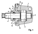
- the in the Fig. 1 illustrated and known from the prior art high-pressure pump comprises a pump housing 1, in which for receiving and rotatable mounting of a drive shaft 2 about a drive shaft longitudinal axis 4, a flange-shaped housing part 5 is added. To form a sliding bearing a plain bearing bush 11 is inserted in a bearing bore 6 of the housing part 5. The drive shaft 2 is guided through the plain bearing bushing 11 and held at the end in a further bearing arrangement designed as a slide bearing in the pump housing 1. Between the two slide bearings, the drive shaft 2 has a cam drive 3 for actuating a pump piston (not shown) of at least one pump element (also not shown) for conveying fuel.
- the housing part 5 is struck axially on the pump housing 1 via its flange 14.
- the flange 14 is screwed by at least one screw 15 with the pump housing.
- 4 or 6 screws 15 are arranged at the same angular distance from one another in the flange 14 for fastening the housing part 5.
- the screws 15 cause a positive connection through which axial forces introduced via the drive shaft 2 can be accommodated.
- Via a cylindrical projection on the flange 14, the housing part 5 is also supported in the radial direction in a recess 8 of the pump housing 1.
- At least one sealing ring 13 is arranged to prevent the escape of a certain Lagerschmiermenge.
- a corresponding function has a shaft seal 16, which seals the bearing gap between the drive shaft 2 and the housing part 5 to the outside.
- annular groove 12 is formed in an end face of the housing part 5, which ensures a certain elastic deformability of the housing part 5 in the edge region of the bearing.
- the elastic deformability brought about by the annular groove 12 is particularly advantageous when high transverse forces from the cam drive 3 act on the drive shaft 2 and thus lead to a tilting of the drive shaft 2 with respect to the drive shaft longitudinal axis 4. In such a case, the edge regions of the bearing experience a high load, which, however, can be reduced by a corresponding elastic deformation.
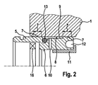
- a erfidnungsdorfe high-pressure pump differs from the high-pressure pump described above in that the housing part 5 is frictionally connected to the pump housing 1 via a press connection 7, wherein the frictional press connection is produced in that the housing part 5 in at least one section a, b, a radial excess relative to the recess 8 of the pump housing 1 has, in which the housing part 5 is received.
- a screwing of the housing part 5 with the pump housing 1 is thus unnecessary, so that the formation of a flange 14 is not required. This saves material and weight.
- the housing part 5 of the embodiments of Figures 2 and 3 is therefore substantially hollow cylindrical.
- a press connection 7 is considered to be sufficient over only a radially oversized portion a for fixing the housing part 5 on the pump housing 1, the embodiment with two press dressings for the reasons mentioned below is preferred.
- the housing part 5 has two sections a and b, which have a radial excess with respect to the recess 8 of the pump housing 1.
- a press connection 7 is produced in sections a and b.
- the sections a and b are axially spaced from one another on the housing part 5, so that an annular space 9 is formed between the sections a and b.
- the annular space 9 is used as a return groove to supply via a return bore 10 a certain amount of bearing lubricant back to a system return (not shown).
- the return bore 10 is designed as a radial bore.
- section b Opposite the pump interior of the annular space 9 is sealed by the press connection 7 of the section a, the radial excess is dimensioned such that the press connection 7 at the same time exerts a sealing function.
- section b has no axial excess sufficient for the exercise of a sealing function, so that the annular space 9 is sealed to the outside via a sealing ring 13.
- Such a sealing ring 13 is dispensable, although the radial excess of the portion b relative to the recess 8 of the pump housing 1 is raised to a corresponding level.
- the sealing of the drive shaft 2 relative to the housing part 5 takes over a shaft seal 16th
- FIG. 2 In the embodiment of the FIG. 2 is in the bearing bore 6 of the housing part 5 a collar bushing used as a plain bearing bush 11.
- the housing part 5 in this area has an annular groove 12 introduced on the front side, on account of which the edge region of the housing part 5 can deform elastically. Deformation of the plain bearing bush is prevented, so that the bearing capacity of the bearing is still ensured.
- annular groove 12 may also be formed on an end face of the pump housing 1.
- the annular groove 12 compensates in the present example, the interference pressure of the press connection 7 of the section b, by allowing an elastic deformation of the pump housing 1.
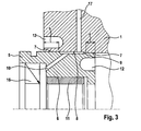
- FIG. 3 continues to differ from that of the FIG. 2 by the plain bearing bush 11 is cylindrical and not designed as a collar bushing.
- a collar portion 18 may be formed on the housing part 5.
- the return bore 10 is not designed as a radial bore, but running obliquely. About the annulus 10, the return bore 10 is in communication with a housing bore 17, which in turn is connected to the system return.
Landscapes
- Engineering & Computer Science (AREA)
- General Engineering & Computer Science (AREA)
- Mechanical Engineering (AREA)
- Chemical & Material Sciences (AREA)
- Combustion & Propulsion (AREA)
- Fuel-Injection Apparatus (AREA)
- Details And Applications Of Rotary Liquid Pumps (AREA)
- Details Of Reciprocating Pumps (AREA)
Claims (7)
- Pompe de carburant haute pression d'un moteur à combustion interne, comprenant un carter de pompe (1), dans lequel, pour l'actionnement d'au moins un élément de pompe disposé dans le carter de pompe (1), est reçu un arbre d'entraînement (2) avec un entraînement à came ou excentrique (3), lequel arbre d'entraînement est monté de manière rotative autour d'un axe longitudinal d'arbre d'entraînement (4), le carter de pompe (1) comprenant, pour recevoir et supporter à rotation l'arbre d'entraînement (2), une partie de carter (5) avec un alésage de palier (6), laquelle partie de carter est connectée au carter de pompe (1) par le biais d'une connexion par pressage à engagement par friction (7),
la partie de carter (5) présentant une première portion (a) et une deuxième portion (b) avec un surdimensionnement radial par rapport à un évidement (8) du carter de pompe (1), dans lequel évidement est insérée la partie de carter (5), pour réaliser la connexion par pressage à engagement par friction (7), la première portion (a) et la deuxième portion (b) étant espacées l'une de l'autre dans la direction axiale par rapport à l'axe longitudinal de l'arbre d'entraînement (4),
caractérisée en ce qu'entre les deux portions (a, b) subsiste un espace annulaire (9) en tant que rainure de retour, dans laquelle débouche un alésage de retour (10). - Pompe de carburant haute pression selon la revendication 1, caractérisée en ce que le surdimensionnement radial de la première portion (a) et de la deuxième portion (b) de la partie de carter (5) par rapport à l'évidement (8) du carter de pompe (1) est différent, le surdimensionnement radial de la deuxième portion (b) étant choisi de préférence supérieur.
- Pompe de carburant haute pression selon l'une quelconque des revendications précédentes,
caractérisée en ce que la connexion par pressage dans la région de la deuxième portion (b) possède en outre une fonction d'étanchéité. - Pompe de carburant haute pression selon l'une quelconque des revendications précédentes,
caractérisée en ce que pour éviter une déformation de l'alésage de palier (6) de la partie de carter (5) ou d'une douille de palier lisse (11) disposée dans l'alésage de palier (6) dans le carter de pompe (1) dans la région d'au moins une connexion par pressage (7), il est prévu une rainure annulaire (12), qui provoque une déformation élastique du carter de pompe (1) et donc un désaccouplement dans la région de la connexion par pressage (7), la rainure annulaire (12) étant disposée de préférence coaxialement à l'évidement (8) du carter de pompe (1) et étant munie d'un rayon insensible aux entailles. - Pompe de carburant haute pression selon la revendication 4,
caractérisée en ce que l'étendue axiale de la rainure annulaire (12) dans le carter de pompe (1) est choisie supérieure à l'étendue axiale de la portion respective (a, b) avec un surdimensionnement radial, l'étendue axiale de la rainure annulaire (12) étant choisie de préférence supérieure d'au moins 20 %. - Pompe de carburant haute pression selon l'une quelconque des revendications précédentes,
caractérisée en ce que pour la fixation en position axiale de la partie de carter (5) à l'intérieur de l'évidement (8) du carter de pompe (1), on prévoit en outre une connexion par engagement positif de la partie de carter (5) avec le carter de pompe (1). - Pompe de carburant haute pression selon l'une quelconque des revendications précédentes,
caractérisée en ce que la partie de carter (5) et le carter de pompe (1) se composent du même matériau.
Applications Claiming Priority (2)
| Application Number | Priority Date | Filing Date | Title |
|---|---|---|---|
| DE200910028795 DE102009028795A1 (de) | 2009-08-21 | 2009-08-21 | Kraftstoffhochdruckpumpe |
| PCT/EP2010/058914 WO2011020635A1 (fr) | 2009-08-21 | 2010-06-23 | Pompe de carburant haute pression |
Publications (2)
| Publication Number | Publication Date |
|---|---|
| EP2467592A1 EP2467592A1 (fr) | 2012-06-27 |
| EP2467592B1 true EP2467592B1 (fr) | 2013-08-14 |
Family
ID=42670439
Family Applications (1)
| Application Number | Title | Priority Date | Filing Date |
|---|---|---|---|
| EP10728193.3A Active EP2467592B1 (fr) | 2009-08-21 | 2010-06-23 | Pompe de carburant haute pression |
Country Status (7)
| Country | Link |
|---|---|
| EP (1) | EP2467592B1 (fr) |
| JP (1) | JP5379307B2 (fr) |
| KR (1) | KR101694571B1 (fr) |
| CN (1) | CN102483017B (fr) |
| DE (1) | DE102009028795A1 (fr) |
| RU (1) | RU2556954C2 (fr) |
| WO (1) | WO2011020635A1 (fr) |
Families Citing this family (3)
| Publication number | Priority date | Publication date | Assignee | Title |
|---|---|---|---|---|
| DE102012210184A1 (de) * | 2012-06-18 | 2013-12-19 | Robert Bosch Gmbh | Hochdruckpumpe für ein Kraftstoffeinspritzsystem |
| CN108779751B (zh) * | 2016-02-02 | 2020-09-08 | 瓦锡兰芬兰有限公司 | 轴承装置和用于共轨燃料喷射系统的高压泵 |
| DE102018216850A1 (de) * | 2018-10-01 | 2020-04-02 | Robert Bosch Gmbh | Kraftstoffhochdruckpumpe mit einem Anschlussstutzen |
Family Cites Families (12)
| Publication number | Priority date | Publication date | Assignee | Title |
|---|---|---|---|---|
| US5215449A (en) * | 1991-12-05 | 1993-06-01 | Stanadyne Automotive Corp. | Distributor type fuel injection pump |
| US5688110A (en) * | 1995-06-02 | 1997-11-18 | Stanadyne Automotive Corp. | Fuel pump arrangement having cam driven low and high pressure reciprocating plunger pump units |
| DE19916376A1 (de) * | 1999-04-12 | 2000-10-19 | Mannesmann Rexroth Ag | Pumpengehäuse |
| JP3875441B2 (ja) | 2000-01-26 | 2007-01-31 | 三菱電機株式会社 | 高圧燃料ポンプ |
| KR100362808B1 (ko) * | 2000-04-21 | 2002-11-27 | 삼성광주전자 주식회사 | 수지몰드형 무브러시 직류모터 및 그 제조방법 |
| DE10029431A1 (de) * | 2000-06-15 | 2001-12-20 | Siemens Ag | Bohrungsanordnung mit einer aus mindestens zwei Bohrungen gebildeten Verschneidung sowie Verfahren zu deren Herstellung |
| DE10221305A1 (de) * | 2002-05-14 | 2003-11-27 | Bosch Gmbh Robert | Radialkolbenpumpe für Kraftstoffeinspritzsystem mit verbesserter Hochdruckfestigkeit |
| DE10259178A1 (de) * | 2002-12-18 | 2004-07-08 | Robert Bosch Gmbh | Hochdruckpumpe für eine Kraftstoffspritzeinrichtung einer Brennkraftmaschine |
| JP4614740B2 (ja) * | 2004-11-17 | 2011-01-19 | パナソニック株式会社 | スピンドルモータ |
| DE102006051332A1 (de) | 2006-10-31 | 2008-05-08 | Robert Bosch Gmbh | Förderpumpe, insbesondere zur Förderung von Dieselkraftstoff mit einer verbesserten Lagerung der Antriebswelle |
| DE102007048853A1 (de) * | 2007-10-11 | 2009-04-16 | Robert Bosch Gmbh | Flansch einer Hochdruckkraftstoffpumpe |
| DE102008007224A1 (de) * | 2008-02-01 | 2009-08-06 | Continental Automotive Gmbh | Pumpenanordnung zur Förderung eines Fluids, Verfahren zur Herstellung einer Pumpenanordnung und System mit einer Pumpenanordnung |
-
2009
- 2009-08-21 DE DE200910028795 patent/DE102009028795A1/de not_active Withdrawn
-
2010
- 2010-06-23 KR KR1020127004316A patent/KR101694571B1/ko not_active Expired - Fee Related
- 2010-06-23 JP JP2012525100A patent/JP5379307B2/ja not_active Expired - Fee Related
- 2010-06-23 RU RU2012110484/06A patent/RU2556954C2/ru active
- 2010-06-23 EP EP10728193.3A patent/EP2467592B1/fr active Active
- 2010-06-23 WO PCT/EP2010/058914 patent/WO2011020635A1/fr not_active Ceased
- 2010-06-23 CN CN201080037048.XA patent/CN102483017B/zh active Active
Also Published As
| Publication number | Publication date |
|---|---|
| CN102483017A (zh) | 2012-05-30 |
| DE102009028795A1 (de) | 2011-02-24 |
| RU2556954C2 (ru) | 2015-07-20 |
| EP2467592A1 (fr) | 2012-06-27 |
| JP2013502523A (ja) | 2013-01-24 |
| JP5379307B2 (ja) | 2013-12-25 |
| RU2012110484A (ru) | 2013-10-27 |
| WO2011020635A1 (fr) | 2011-02-24 |
| KR20120046750A (ko) | 2012-05-10 |
| KR101694571B1 (ko) | 2017-01-17 |
| CN102483017B (zh) | 2014-10-29 |
Similar Documents
| Publication | Publication Date | Title |
|---|---|---|
| EP4214417B1 (fr) | Ensemble piston-cylindre pour un compresseur à pistons radiaux et compresseur à pistons radiaux | |
| DE10161715A1 (de) | Elektrische Hilfskraftlenkung für Kraftfahrzeuge | |
| EP3421802B1 (fr) | Pompe à gaz avec limiteur de pression pour la réduction du couple de démarrage | |
| WO2018059900A1 (fr) | Poussoir à galet pour une pompe à piston et pompe à piston | |
| WO1997005388A1 (fr) | Pompe a piston | |
| WO2020136269A1 (fr) | Pompe rotative à compensation axiale, garniture d'étanchéité de sortie pour une pompe et ensemble pompe prémonté | |
| EP2467592B1 (fr) | Pompe de carburant haute pression | |
| EP4314560B1 (fr) | Machine fluidique à engrenages intérieurs et procédé de fabrication d'une machine fluidique à engrenages intérieurs | |
| AT519652B1 (de) | Dichtungsvorrichtung und Hydraulikkolben mit Dichtungsvorrichtung | |
| EP3903006A1 (fr) | Pompe rotative à compensation axiale, garniture d'étanchéité de sortie pour une pompe et ensemble pompe prémonté | |
| DE10322595B4 (de) | Kolbenpumpe, sowie Verfahren zu ihrer Herstellung | |
| EP2419635A1 (fr) | Pompe à piston avec entraînement par came, en particulier pompe à carburant | |
| WO2011098314A1 (fr) | Pompe à carburant haute pression | |
| EP1929154B1 (fr) | Pompe a piston | |
| EP2207958B1 (fr) | Pompe à pistons radiaux à corps de base prismatique pour système d'injection de carburant | |
| WO2007138093A1 (fr) | Pompe volumétrique réglable | |
| WO2017148841A1 (fr) | Piston pour pompe à carburant haute pression à piston et pompe à carburant haute pression à piston | |
| DE102009028997A1 (de) | Kraftstoffhochdruckpumpe | |
| DE102020203529B3 (de) | Anordnung und Verfahren zum Herstellen einer Anordnung für eine Kraftstoffhochdruckpumpe und Kraftstoffhochdruckpumpe für ein Kraftfahrzeug | |
| EP2872778B1 (fr) | Pompe à haute pression | |
| EP1515883A1 (fr) | Groupe motopompe, destine notamment a des systemes de freinage a regulation antipatinage | |
| WO2018069134A1 (fr) | Poussoir à galet pour pompe à piston et pompe à piston | |
| DE102022213122A1 (de) | Kolbenpumpe, insbesondere Kraftstoff-Hochdruckpumpe für ein Kraftstoffsystem einer Brennkraftmaschine | |
| DE102015210798B4 (de) | Kraftstoffhochdruckpumpe | |
| DE102010042437B4 (de) | Hochdruckpumpe |
Legal Events
| Date | Code | Title | Description |
|---|---|---|---|
| PUAI | Public reference made under article 153(3) epc to a published international application that has entered the european phase |
Free format text: ORIGINAL CODE: 0009012 |
|
| 17P | Request for examination filed |
Effective date: 20120321 |
|
| AK | Designated contracting states |
Kind code of ref document: A1 Designated state(s): AL AT BE BG CH CY CZ DE DK EE ES FI FR GB GR HR HU IE IS IT LI LT LU LV MC MK MT NL NO PL PT RO SE SI SK SM TR |
|
| DAX | Request for extension of the european patent (deleted) | ||
| GRAP | Despatch of communication of intention to grant a patent |
Free format text: ORIGINAL CODE: EPIDOSNIGR1 |
|
| INTG | Intention to grant announced |
Effective date: 20130426 |
|
| GRAS | Grant fee paid |
Free format text: ORIGINAL CODE: EPIDOSNIGR3 |
|
| GRAA | (expected) grant |
Free format text: ORIGINAL CODE: 0009210 |
|
| AK | Designated contracting states |
Kind code of ref document: B1 Designated state(s): AL AT BE BG CH CY CZ DE DK EE ES FI FR GB GR HR HU IE IS IT LI LT LU LV MC MK MT NL NO PL PT RO SE SI SK SM TR |
|
| REG | Reference to a national code |
Ref country code: GB Ref legal event code: FG4D Free format text: NOT ENGLISH |
|
| REG | Reference to a national code |
Ref country code: CH Ref legal event code: EP Ref country code: AT Ref legal event code: REF Ref document number: 627019 Country of ref document: AT Kind code of ref document: T Effective date: 20130815 |
|
| REG | Reference to a national code |
Ref country code: IE Ref legal event code: FG4D Free format text: LANGUAGE OF EP DOCUMENT: GERMAN |
|
| REG | Reference to a national code |
Ref country code: DE Ref legal event code: R096 Ref document number: 502010004383 Country of ref document: DE Effective date: 20131010 |
|
| REG | Reference to a national code |
Ref country code: NL Ref legal event code: VDEP Effective date: 20130814 |
|
| REG | Reference to a national code |
Ref country code: LT Ref legal event code: MG4D |
|
| PG25 | Lapsed in a contracting state [announced via postgrant information from national office to epo] |
Ref country code: NO Free format text: LAPSE BECAUSE OF FAILURE TO SUBMIT A TRANSLATION OF THE DESCRIPTION OR TO PAY THE FEE WITHIN THE PRESCRIBED TIME-LIMIT Effective date: 20131114 Ref country code: SE Free format text: LAPSE BECAUSE OF FAILURE TO SUBMIT A TRANSLATION OF THE DESCRIPTION OR TO PAY THE FEE WITHIN THE PRESCRIBED TIME-LIMIT Effective date: 20130814 Ref country code: CY Free format text: LAPSE BECAUSE OF FAILURE TO SUBMIT A TRANSLATION OF THE DESCRIPTION OR TO PAY THE FEE WITHIN THE PRESCRIBED TIME-LIMIT Effective date: 20130828 Ref country code: LT Free format text: LAPSE BECAUSE OF FAILURE TO SUBMIT A TRANSLATION OF THE DESCRIPTION OR TO PAY THE FEE WITHIN THE PRESCRIBED TIME-LIMIT Effective date: 20130814 Ref country code: PT Free format text: LAPSE BECAUSE OF FAILURE TO SUBMIT A TRANSLATION OF THE DESCRIPTION OR TO PAY THE FEE WITHIN THE PRESCRIBED TIME-LIMIT Effective date: 20131216 Ref country code: IS Free format text: LAPSE BECAUSE OF FAILURE TO SUBMIT A TRANSLATION OF THE DESCRIPTION OR TO PAY THE FEE WITHIN THE PRESCRIBED TIME-LIMIT Effective date: 20131214 Ref country code: HR Free format text: LAPSE BECAUSE OF FAILURE TO SUBMIT A TRANSLATION OF THE DESCRIPTION OR TO PAY THE FEE WITHIN THE PRESCRIBED TIME-LIMIT Effective date: 20130814 |
|
| PG25 | Lapsed in a contracting state [announced via postgrant information from national office to epo] |
Ref country code: LV Free format text: LAPSE BECAUSE OF FAILURE TO SUBMIT A TRANSLATION OF THE DESCRIPTION OR TO PAY THE FEE WITHIN THE PRESCRIBED TIME-LIMIT Effective date: 20130814 Ref country code: GR Free format text: LAPSE BECAUSE OF FAILURE TO SUBMIT A TRANSLATION OF THE DESCRIPTION OR TO PAY THE FEE WITHIN THE PRESCRIBED TIME-LIMIT Effective date: 20131115 Ref country code: PL Free format text: LAPSE BECAUSE OF FAILURE TO SUBMIT A TRANSLATION OF THE DESCRIPTION OR TO PAY THE FEE WITHIN THE PRESCRIBED TIME-LIMIT Effective date: 20130814 Ref country code: FI Free format text: LAPSE BECAUSE OF FAILURE TO SUBMIT A TRANSLATION OF THE DESCRIPTION OR TO PAY THE FEE WITHIN THE PRESCRIBED TIME-LIMIT Effective date: 20130814 Ref country code: SI Free format text: LAPSE BECAUSE OF FAILURE TO SUBMIT A TRANSLATION OF THE DESCRIPTION OR TO PAY THE FEE WITHIN THE PRESCRIBED TIME-LIMIT Effective date: 20130814 |
|
| PG25 | Lapsed in a contracting state [announced via postgrant information from national office to epo] |
Ref country code: CY Free format text: LAPSE BECAUSE OF FAILURE TO SUBMIT A TRANSLATION OF THE DESCRIPTION OR TO PAY THE FEE WITHIN THE PRESCRIBED TIME-LIMIT Effective date: 20130814 |
|
| PG25 | Lapsed in a contracting state [announced via postgrant information from national office to epo] |
Ref country code: DK Free format text: LAPSE BECAUSE OF FAILURE TO SUBMIT A TRANSLATION OF THE DESCRIPTION OR TO PAY THE FEE WITHIN THE PRESCRIBED TIME-LIMIT Effective date: 20130814 Ref country code: SK Free format text: LAPSE BECAUSE OF FAILURE TO SUBMIT A TRANSLATION OF THE DESCRIPTION OR TO PAY THE FEE WITHIN THE PRESCRIBED TIME-LIMIT Effective date: 20130814 Ref country code: RO Free format text: LAPSE BECAUSE OF FAILURE TO SUBMIT A TRANSLATION OF THE DESCRIPTION OR TO PAY THE FEE WITHIN THE PRESCRIBED TIME-LIMIT Effective date: 20130814 Ref country code: CZ Free format text: LAPSE BECAUSE OF FAILURE TO SUBMIT A TRANSLATION OF THE DESCRIPTION OR TO PAY THE FEE WITHIN THE PRESCRIBED TIME-LIMIT Effective date: 20130814 Ref country code: NL Free format text: LAPSE BECAUSE OF FAILURE TO SUBMIT A TRANSLATION OF THE DESCRIPTION OR TO PAY THE FEE WITHIN THE PRESCRIBED TIME-LIMIT Effective date: 20130814 Ref country code: EE Free format text: LAPSE BECAUSE OF FAILURE TO SUBMIT A TRANSLATION OF THE DESCRIPTION OR TO PAY THE FEE WITHIN THE PRESCRIBED TIME-LIMIT Effective date: 20130814 |
|
| PG25 | Lapsed in a contracting state [announced via postgrant information from national office to epo] |
Ref country code: IT Free format text: LAPSE BECAUSE OF FAILURE TO SUBMIT A TRANSLATION OF THE DESCRIPTION OR TO PAY THE FEE WITHIN THE PRESCRIBED TIME-LIMIT Effective date: 20130814 Ref country code: ES Free format text: LAPSE BECAUSE OF FAILURE TO SUBMIT A TRANSLATION OF THE DESCRIPTION OR TO PAY THE FEE WITHIN THE PRESCRIBED TIME-LIMIT Effective date: 20130814 |
|
| PLBE | No opposition filed within time limit |
Free format text: ORIGINAL CODE: 0009261 |
|
| STAA | Information on the status of an ep patent application or granted ep patent |
Free format text: STATUS: NO OPPOSITION FILED WITHIN TIME LIMIT |
|
| 26N | No opposition filed |
Effective date: 20140515 |
|
| REG | Reference to a national code |
Ref country code: DE Ref legal event code: R097 Ref document number: 502010004383 Country of ref document: DE Effective date: 20140515 |
|
| PG25 | Lapsed in a contracting state [announced via postgrant information from national office to epo] |
Ref country code: MC Free format text: LAPSE BECAUSE OF FAILURE TO SUBMIT A TRANSLATION OF THE DESCRIPTION OR TO PAY THE FEE WITHIN THE PRESCRIBED TIME-LIMIT Effective date: 20130814 Ref country code: LU Free format text: LAPSE BECAUSE OF FAILURE TO SUBMIT A TRANSLATION OF THE DESCRIPTION OR TO PAY THE FEE WITHIN THE PRESCRIBED TIME-LIMIT Effective date: 20140623 |
|
| REG | Reference to a national code |
Ref country code: CH Ref legal event code: PL |
|
| GBPC | Gb: european patent ceased through non-payment of renewal fee |
Effective date: 20140623 |
|
| REG | Reference to a national code |
Ref country code: IE Ref legal event code: MM4A |
|
| REG | Reference to a national code |
Ref country code: FR Ref legal event code: ST Effective date: 20150227 |
|
| PG25 | Lapsed in a contracting state [announced via postgrant information from national office to epo] |
Ref country code: LI Free format text: LAPSE BECAUSE OF NON-PAYMENT OF DUE FEES Effective date: 20140630 Ref country code: CH Free format text: LAPSE BECAUSE OF NON-PAYMENT OF DUE FEES Effective date: 20140630 Ref country code: IE Free format text: LAPSE BECAUSE OF NON-PAYMENT OF DUE FEES Effective date: 20140623 |
|
| PG25 | Lapsed in a contracting state [announced via postgrant information from national office to epo] |
Ref country code: FR Free format text: LAPSE BECAUSE OF NON-PAYMENT OF DUE FEES Effective date: 20140630 Ref country code: GB Free format text: LAPSE BECAUSE OF NON-PAYMENT OF DUE FEES Effective date: 20140623 |
|
| PG25 | Lapsed in a contracting state [announced via postgrant information from national office to epo] |
Ref country code: MT Free format text: LAPSE BECAUSE OF FAILURE TO SUBMIT A TRANSLATION OF THE DESCRIPTION OR TO PAY THE FEE WITHIN THE PRESCRIBED TIME-LIMIT Effective date: 20130814 |
|
| PG25 | Lapsed in a contracting state [announced via postgrant information from national office to epo] |
Ref country code: SM Free format text: LAPSE BECAUSE OF FAILURE TO SUBMIT A TRANSLATION OF THE DESCRIPTION OR TO PAY THE FEE WITHIN THE PRESCRIBED TIME-LIMIT Effective date: 20130814 |
|
| PG25 | Lapsed in a contracting state [announced via postgrant information from national office to epo] |
Ref country code: BG Free format text: LAPSE BECAUSE OF FAILURE TO SUBMIT A TRANSLATION OF THE DESCRIPTION OR TO PAY THE FEE WITHIN THE PRESCRIBED TIME-LIMIT Effective date: 20130814 |
|
| PG25 | Lapsed in a contracting state [announced via postgrant information from national office to epo] |
Ref country code: BE Free format text: LAPSE BECAUSE OF FAILURE TO SUBMIT A TRANSLATION OF THE DESCRIPTION OR TO PAY THE FEE WITHIN THE PRESCRIBED TIME-LIMIT Effective date: 20140630 Ref country code: HU Free format text: LAPSE BECAUSE OF FAILURE TO SUBMIT A TRANSLATION OF THE DESCRIPTION OR TO PAY THE FEE WITHIN THE PRESCRIBED TIME-LIMIT; INVALID AB INITIO Effective date: 20100623 Ref country code: TR Free format text: LAPSE BECAUSE OF FAILURE TO SUBMIT A TRANSLATION OF THE DESCRIPTION OR TO PAY THE FEE WITHIN THE PRESCRIBED TIME-LIMIT Effective date: 20130814 |
|
| REG | Reference to a national code |
Ref country code: AT Ref legal event code: MM01 Ref document number: 627019 Country of ref document: AT Kind code of ref document: T Effective date: 20150623 |
|
| PG25 | Lapsed in a contracting state [announced via postgrant information from national office to epo] |
Ref country code: AT Free format text: LAPSE BECAUSE OF NON-PAYMENT OF DUE FEES Effective date: 20150623 |
|
| PG25 | Lapsed in a contracting state [announced via postgrant information from national office to epo] |
Ref country code: MK Free format text: LAPSE BECAUSE OF FAILURE TO SUBMIT A TRANSLATION OF THE DESCRIPTION OR TO PAY THE FEE WITHIN THE PRESCRIBED TIME-LIMIT Effective date: 20130814 |
|
| PG25 | Lapsed in a contracting state [announced via postgrant information from national office to epo] |
Ref country code: AL Free format text: LAPSE BECAUSE OF FAILURE TO SUBMIT A TRANSLATION OF THE DESCRIPTION OR TO PAY THE FEE WITHIN THE PRESCRIBED TIME-LIMIT Effective date: 20130814 |
|
| PGFP | Annual fee paid to national office [announced via postgrant information from national office to epo] |
Ref country code: DE Payment date: 20250814 Year of fee payment: 16 |