EP2470925B1 - Procédé et dispositif radio pour la détection d'un mouvement - Google Patents
Procédé et dispositif radio pour la détection d'un mouvement Download PDFInfo
- Publication number
- EP2470925B1 EP2470925B1 EP10754696.2A EP10754696A EP2470925B1 EP 2470925 B1 EP2470925 B1 EP 2470925B1 EP 10754696 A EP10754696 A EP 10754696A EP 2470925 B1 EP2470925 B1 EP 2470925B1
- Authority
- EP
- European Patent Office
- Prior art keywords
- sequence
- receiver
- maximum
- transmitter
- movement
- Prior art date
- Legal status (The legal status is an assumption and is not a legal conclusion. Google has not performed a legal analysis and makes no representation as to the accuracy of the status listed.)
- Not-in-force
Links
Images

Classifications
-
- G—PHYSICS
- G01—MEASURING; TESTING
- G01S—RADIO DIRECTION-FINDING; RADIO NAVIGATION; DETERMINING DISTANCE OR VELOCITY BY USE OF RADIO WAVES; LOCATING OR PRESENCE-DETECTING BY USE OF THE REFLECTION OR RERADIATION OF RADIO WAVES; ANALOGOUS ARRANGEMENTS USING OTHER WAVES
- G01S11/00—Systems for determining distance or velocity not using reflection or reradiation
- G01S11/02—Systems for determining distance or velocity not using reflection or reradiation using radio waves
- G01S11/06—Systems for determining distance or velocity not using reflection or reradiation using radio waves using intensity measurements
-
- G—PHYSICS
- G01—MEASURING; TESTING
- G01S—RADIO DIRECTION-FINDING; RADIO NAVIGATION; DETERMINING DISTANCE OR VELOCITY BY USE OF RADIO WAVES; LOCATING OR PRESENCE-DETECTING BY USE OF THE REFLECTION OR RERADIATION OF RADIO WAVES; ANALOGOUS ARRANGEMENTS USING OTHER WAVES
- G01S5/00—Position-fixing by co-ordinating two or more direction or position line determinations; Position-fixing by co-ordinating two or more distance determinations
- G01S5/02—Position-fixing by co-ordinating two or more direction or position line determinations; Position-fixing by co-ordinating two or more distance determinations using radio waves
- G01S5/14—Determining absolute distances from a plurality of spaced points of known location
Definitions
- the invention relates to a method and a radio device for detecting a movement of at least one power-saving receiver.
- reception field strengths or dependent thereon variables In order to make statements about distances or movements in radio systems, it is known to evaluate reception field strengths or dependent thereon variables. To determine a position of a mobile radio node, for example in a plane, several, for example at least three distance estimates are required.
- RSSI signal Receiveived Signal Strength Indicator
- an analog voltage is usually generated which corresponds to the logarithmic level measure of the amplitude of the high-frequency received carrier signal.
- the generation of such an RSSI signal is performed with a cascade of logarithmic amplifier cells, the individual characteristics of which form the overall characteristic curve with greater input level dynamics.
- the high-frequency receiver section of the radio receiver is switched on. The power requirements of analog RSSI circuits that provide a signal for the quality of the received signal does not allow years of operation with coin cell batteries.
- radio node networks also called sensor node networks, which are based on standard transceivers
- polling is used to save power.
- the receivers are only activated at certain times for a short time. In this time will be the communication is processed, then the receiver is switched off again. Thus, the receiver is not active most of the time and thus unreachable for a wireless connection. It comes to increasing the reaction time or to undesirable latencies. This leads, for example, to the fact that a longer time has to be sent until the polling-operated radio receiver has received the message. A sometimes permanent occupancy of the radio channel may be the result.
- the power consumption of PLL-based standard radio receivers that provide an RSSI signal is above 10 mA.
- Such receivers can still be battery operated with the polling method, however, in wireless networks that use polling, the response time of a radio node increases with decreasing duty cycle, which in turn is intolerable for many applications.
- Power-saving receivers can be implemented, for example, as a super-regenerative or detector receiver.
- the achievable current consumption is around 100 ⁇ A.
- the low power receiver has moderate to low sensitivities and reduced selectivity.
- the disadvantages of increased latency or reaction times in polling method can be omitted here, if a continuous operation of such a low-power radio receiver in the application is possible.
- Such power-saving receivers are commonly used as wake-up receivers in the radio node networks, which when received on a special activation sequence wakes up the rest of the system connected and operating in power saving mode (eg, sleep mode). If a lithium coin cell with 1000 mAh is used for the power supply of such a wake-up receiver, then a 100 .mu.A receiver can be operated continuously for 14 months.
- US 2008/0232281 A1 discloses an apparatus and method for locating a radio node in a sensor network in which radio signals are transmitted from a plurality of fixed transmitters of known positions to the mobile radio node, wherein, depending on the received RSSI signal, the position of the radio node is calculated.
- WO 2009/033001 A2 describes a radio sensor network with transmitters and receivers using between a temporal link signature that includes a pulse response of a signal transmitted by a transmitter over a radio channel between transmitter and receiver.
- Patent Abstract of Japan JP 2009 06 5394 relates to a radio node network in which the position of a mobile node is estimated using the attenuation of reception field strength information at a fixed node.
- the invention has for its object to provide a method and a radio device for power-saving detection of a movement of at least one power-saving receiver, with which a significant movement of the receiver or a mobile radio node containing them over a long period of time in a relatively simple manner without complex computational work can be detected.
- the radio signals that are sent from at least one transmitter to the at least one receiver and which are modulated as predetermined bit sequences on a high-frequency carrier in a receiving sequence be demodulated and that in a downstream correlator unit, the receiving sequence with a reference sequence corresponding to the predetermined bit sequence is formed and stored is correlated, can be determined depending on the determined by the correlation distances of the actual correlation maxima to a predetermined value quality measures for the received field strength at the receiver, further by sending the radio signals with the predetermined bit sequence with at least two different transmission powers in one Sequence and repetition of the sequence on the one hand quality measures of the receiving sequences can be determined depending on the time and on the other hand by the graded transmission powers an extension of the distance ranges is achieved, in which the presence of movements of the receiver by an evaluation device can be determined depending on the quality measures ,
- the correspondences determined by correlation stand for error-free reception in which all bits of the receive bit sequence are equal to the expected bit sequence.
- the errors detected by the correlation represent an erroneous transmission and are present when there are inequalities to the expected correlation sequence in the received correlation sequence.
- the possibility of using a value of the quality measure (QM value) to estimate a movement within different distance ranges (distance classes) essentially depends on the code length, ie on the length of the given bit sequence. In this case, for example, when varying the values of the quality measure at a transmission power x different, eg with a bit sequence of 32 bits three, with a little more uncertainty four different distances or distances of the receiver from the transmitter can be estimated.
- the evaluation device for detecting a movement from the quality measures may be integrated in the receiver or provided externally or may also be partially arranged in the receiver and partially externally. It is important that also in the receiver partially or completely integrated evaluation device is designed to save energy. For this purpose, low-complexity digital circuits such as adders, comparators or the like are suitable. An evaluation in a complex signal processor is not required.
- the evaluation device may, for example, also include static RAM in the radio receiver, in which quality measures and / or movement and / or relative position data are stored, which are read out centrally when needed, for example via an active, power-consuming wireless sensor network and evaluated. This makes it possible to trace back radio receivers attached to valuable goods.
- the components of the receiver required for the evaluation of the quality measures such as correlator unit comprising shift registers and / or XOR gates, have a low power consumption, so that a continuous operation over a very long time with battery supply is possible.
- a radio-based anti-theft device or a fencing is possible.
- a binary sequence is selected as the reference sequence and thus as the predetermined bit sequence, since this is easy to process.
- the predetermined bit sequence or reference sequence comprises at least 8 bits.
- a long bit sequence for example, with a length of 31 bits and greater, for example, up to 64 bits to choose, since more errors in the reception of radio signals can be tolerated.
- the distance of the actual correlation maximum is selected to a predetermined value. It is particularly advantageous, in addition to the correlation maximum, to distance at least one secondary maximum, eg the highest one.
- the predetermined value can be determined by the maximum achievable or the best possible correlation maximum. It can also be zero, for example.
- the correlation unit correlates the reception bit sequence or sequence with the reference sequence according to a cross correlation function, whereby the detected cross correlation function is equal to the autocorrelation function in undisturbed reception, which can be determined with the predetermined bit sequence and determined in advance.
- the power-saving receiver is designed for demodulation so that it can demodulate radio signals modulated with on-off-keying (OOK) modulation or other multivalued amplitude modulations. This leads to the power-saving design of the receiver, which requires about 5 ⁇ A to less than 100 ⁇ A.
- the number of errors in correlating the receive bitstream with the expected bitstream i. the reference sequence, depending on the signal strength at the radio receiver input.
- the number of errors can be used as a quality measure for the reception field strength.
- the number of errors depends in turn on the sensitivity of the receiver and the type and length of the bit sequence used (predetermined bit sequence, reference sequence).
- the method presented here allows the energy-saving Determining the position or movement of a wireless node.
- the presented method can be carried out in a power-saving manner because no complicated PLL synthesizer-based radio receivers are used; This is especially true for WLAN or Zigbee receivers.
- No active infrastructure of a wireless network (such as WLAN) is required.
- There is no need for a comprehensive calculation procedure such as time-of-arrival (TOA or TDOA) procedures.
- TOA or TDOA time-of-arrival
- the broadcasting of the locating sequences in the transmitters can be used for many (mobile) power-saving radio receivers at the same time.
- the occupancy of the radio channel in the determination of the location information is very low and is also the same for a large number of locating radio receivers.
- Assignments in rooms or grounds with accuracies of a few meters are possible. Further applications of the described method are detection of moving "foreign objects" in a power-saving sensor network as well as the detection of the "radio shadowing direction" in a power-saving sensor network to find new optimal routing paths for multihop sensor networks. A logging of the respective detected position in a memory of the radio node can be done to track paths from radio nodes.
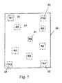
- a radio system is shown within a limited area 20 having a plurality of radio nodes 21 and a plurality of fixed transmitters 22.
- the radio nodes 21 are connected to an object, for example, and can be mobile. They each have a power-saving receiver circuit, as discussed below in connection with Fig. 2 is described, and usually also a transmitter circuit to send signals to other radio nodes or to not shown further receiver arrangements.
- the illustrated system is used to detect at least movements and directions of movement of the radio node 21, wherein the description of the detection of a Movement further down is first made in the context of a fixed transmitter 22 and a radio node 21, both with solid lines in the Fig. 1 are shown.
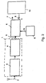
- a receiver circuit is shown, as it is used in a radio node 21 and having a power-saving receiver part 1 as an analog front end.
- the receiver part 1 is connected to an antenna 2 which receives radio signals transmitted by the transmitter 22 as radio frequency (RF) signals in the form of a predetermined low bit rate bit sequence modulated onto an RF carrier signal.
- RF radio frequency
- the receiver part 1 is shown schematically here by a high-frequency amplifier 3 and an OOK demodulator 4, in which the received signals are converted into a receive bit sequence (or receive sequence) which is present at the output 5 of the receiver part 1.
- the receiver part 1 is distinguished by the fact that it is a receiver that is kept very simple, ie with little circuit complexity and reduced sensitivity as well as reduced selectivity. By eliminating complex circuitry and complex modulation techniques, the power consumption of the receiver is reduced and is in the range of 5 ⁇ A to less than 100 ⁇ A. For example, it can be realized as a super-regenerative or detector receiver.
- the receiver part 1 is connected to a correlator unit 6, which can be implemented digital or analog and has, for example, shift registers and logic gates, such as XOR or XNOR gates. This correlator unit is also designed to save energy and consumes a few ⁇ A.
- a storage unit 9, which may also be part of the correlator unit 6, has stored a reference sequence s (t) which is identical to the predetermined bit sequence modulated onto the RF carrier signal.
- the correlator unit 6 may optionally provide an output signal 7 corresponding to the input signal of the receiver part 1 and further generates a signal 8 for a quality measure QM of reception, ie the reception field strength corresponding to the RSSI signal in conventional radio receivers.
- a so-called wake-up receiver can be used, which receives a special activation sequence (predetermined bit sequence) and, after evaluation in the receiving part 1 and the correlator unit 6, the output signal 7 to one or more radio nodes of the Network for their activation sends, which are designed as power-consuming main receiver.
- This allows to operate the radio node network in a very low-power mode (eg sleep mode) and still activate it if necessary.
- the quality measure values of the radio nodes allow, for example in the sensor network or radio network, conclusions about the local reception conditions and can be used to determine optimal routing paths in multihop networks. Obvious is a power control at sending radio node for the purpose of increasing the operating time.
- the values of the quality measure are additionally or solely used to estimate a movement and a direction of movement or to determine a position of a radio node, as will be explained below.
- a correlation function is formed from the reception bit sequence or sequence 5, which is referred to as the reception signal e (t), and the preprogrammed reference sequence s (t) stored in the memory unit 9.
- a cross-correlation function KKF is formed as k (t). With undisturbed reception, the received signal e (t) is equal to s (t), the reference sequence, i. s (t) is correlated with itself. In this ideal case, i. there are no transmission errors, the determined KKF is equal to the autocorrelation function AKF, which is defined directly with the given bit sequence or the reference sequence and can be determined in advance.
- bit sequence s (t) is suitable if it has a pronounced maximum for the autocorrelation function. Furthermore, a large distance to the secondary maximum or to the secondary maxima should be given in this AKF, both of these properties must be maintained even with disturbed reception. For example, the distance should be so high that the maximum lies around several quality measure units above the secondary maxima or over the secondary maxima "carpet", so that the shape of the cross correlation function KKF is maintained even if the transmission is disturbed.
- the maximum must be "fixed” in relation to the time situation in the KKF, ie it must not wander if faults are received with.
- bit sequence s (t) and e (t) binary sequences can be used, in which case the cross-correlation function k (t) is not binary.
- the correlation maximum is highest and the distance to the secondary maximum is also greatest.
- Each additional transmission error causes the main maximum to drop and the secondary maxima to exit. This reduces the distance from the main to secondary maxima.
- a suitable bit sequence is for example one in which a very good cross-correlation function is formed, for example 00111111191111111100, here the distance to the secondary maximum 8 would be disturbed. With two errors the cross-correlation function could look like this: 00111112373211111100. Here the distance to the secondary maximum is still 4.
- the detectable number of errors also depends on the length of the bit sequence used, it makes sense to choose these as long as possible. Practically a length of the sequence from 8 bits makes sense, then errors can be tolerated at the reception. If a 31-bit sequence is used which fulfills the above-mentioned criteria, then up to nine arbitrary transmission errors can be tolerated, whereby the maximum of the cross-correlation function is still pronounced at the same point and a distance to the secondary maximum is still detectable.
- the cross-correlation function e (t) of the reception bit sequence 5, eg 10110111 with the Reference sequence without transmission error and a different number of transmission errors wherein the ordinate represents the signal quality and the abscissa represents the time.
- the cross-correlation function which is at the same time the autocorrelation function without transmission error, has a pronounced maximum with a height of eight and the distance to the secondary maximum is three.
- the height of the correlation maximum here eight, in conjunction with the distance to the secondary maximum, here three, can be used. If only the height of the correlation maximum is selected, then this should be related to the best possible value.
- Fig. 4 shows by way of example the cross-correlation function in a transmission error, wherein it can be seen that the main maximum is still very pronounced and the distance to the secondary maximum is still large. Each added error leads to a decrease in the maximum in the cross-correlation function and a reduction in the distance to the secondary maximum. If too many errors occur during reception, then the maximum characteristic disappears in the KKF, eg if the reception level is too low.
- the described power-saving determination of the signal quality or the received field strength of the received radio-frequency signal can be used to estimate the distance of the receiver circuit (radio node 21) from the transmitter 22 and thus to determine their movement.
- the transmitter 22 transmits its radio signals, that is to say the predetermined bit sequence modulated onto the high-frequency carrier, preferably by the OOK method with different transmission powers, for example, three different transmission powers at predetermined time intervals and the radio node with power-saving receiver receives the radio signals with different reception field strengths.
- values for the quality measures at the different transmission powers are determined and supplied to an evaluation device 10, which can be part of the receiver circuit, but can also be provided elsewhere independently of the radio node, in which case the signals 8 for the quality measures are transmitted via radio be transmitted.
- the receiver circuit in a radio system, which serves for example for theft monitoring, constantly switched on, but it can also be adapted to the time sequence of the transmission of the radio signals with graduated transmission power.
- the span of the quality measures can be extended. For example, if the arrangement after Fig. 1 would be built on an open field without shadowing, the reception would be so good that the quality measure changed only for sufficiently high distance of the radio node or receiver 21 from the transmitter 22, eg only from 50 m. If, for example, the transmission power is reduced by a factor of 10, "poorer" reception is provoked “artificially” so that the quality measure then determined alters its value for smaller distances of the receiver 21 from the transmitter 22, for example as from 16 m. If a further gradation of the transmission power is made, for example once again by a power of ten, then a change in the quality measure is again recognizable for smaller distances, for example from 5 m. By selecting the number of transmission powers corresponding to a successive degradation It is also possible to estimate smaller distances from the transmitter with the quality measure values.
- the evaluation of the quality measures is now carried out in the evaluation unit 10, wherein different methods are conceivable.
- the values of a sequence of radio signals with different transmission powers can be added in the evaluation unit 10 as a measure of the distance between transmitter and receiver.
- the respective determination of such a sum over a larger period and comparison of the respective sums allows the conclusion to a change of location ie to a movement, if the sum value to the previous one significant Deviation shows.
- an addition with differently weighted QM values can also take place.
- the type of evaluation must be finely adjusted on the basis of the gradation of the transmission power in conjunction with the predetermined bit sequence used and also the number of gradations of transmission power must be taken into account in connection with the receiver used, in particular its sensitivity and the predetermined bit sequence used, in particular its code length become
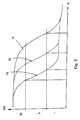
- Fig. 5 For example, QM values are shown as a function of the distance from the transmitter, with curve 11 showing the QM values for the highest power level, curve 12 those of the power level reduced by one order of magnitude and curve 13 reducing those for another one power of ten power stage. If it is assumed that with a single curve 11, 12, 13 of QM values three different distance ranges or distance classes I, II, III are used Fig. 5 shown possibilities, ie with a transmitter with three transmission power levels and a receiver an estimate up to nine distance classes depending on the overlap of the curves possible. As stated, the gradation of the transmission powers must be suitably selected. If the transmission powers are not far enough apart, eg 2: 1, that an overlap of the QMversus distance characteristics can occur.
- the transmission powers are chosen too far apart, eg 100: 1, gaps in the assignment of QM values to distances are possible. If the codes used are longer, more transmission errors per transmission can be tolerated, ie the usable QM value range increases. This allows a finer QM-to-distance mapping respectively.
- Fig. 1 made with a transmitter 22 and a receiver 21 and actually several transmitters are usually provided in Fig. 1
- four transmitters 22 (TX1, TX2, TX3, TX4) are indicated and, for example, six receivers 21, although much more can still be planned.
- each transmitter 22 is assigned a transmitter identifier, for example an identifier with 8 to 16 bits, and the predetermined long bit sequence as a location sequence, eg with 31 bits, can be common to all transmitters 22.
- the transmitters 22 then transmit cyclically, for example, every minute or at irregular times when required or at the request of the user.
- the OOK-modulated carrier signals are transmitted one after the other and the receivers 21 receive the radio signals from all the transmitters 22 and evaluate them respectively to form quality measures, ie values of quality measures.
- the predetermined bit sequence ie the correlation sequence with the transmit detection bit sequence is transmitted sequentially at five different times t1, t2, t3, t4, t5 with three different transmission powers, received by the radio node 21 and with respect to the QM values evaluated.
- the quality measures for different transmission powers are summed for each transmission tl-t5 and stored as QMTX1 to QMTX4, for example in a RAM, these values then being used to detect movements taking into account their significant changes over time.
- each QM value can assume the values 0..8.
- Determination of the direction of movement In the case of transmission t1 to transmission t4, it can be concluded that a distance from transmitter TX1 has taken place while simultaneously approaching transmitter TX3 and then again returning to transmitter TX1. The transmitter TX4 shows no significant changes. With sufficiently large changes of one or more QM values can thus be concluded on the direction.
- a central evaluation unit 10 which collects the values of the quality measures of all receivers 21, for example via a radio transmission and the evaluation of the possible movement, the direction of movement and possibly the relative position makes and Event case, a corresponding message forwards.
- the central evaluation unit also offers the possibility of occasionally reading out the QM values collected in each radio node 21. This allows a follow-up. Reading is greatly simplified if the history of the respective QM values is transmitted only in the case of a detected movement. If no movement is detected, a single, statistical value is sufficient for the central detection. In principle, however, each radio node 21 itself may be able to detect movement and movement direction and, in conjunction with a transmitter located on the radio node 21, wake up the existing radio network and cause a central detection.
- Fig. 1 Another possibility in the presented monitoring after Fig. 1 may be that foreign objects that are within the demarcated area.
- the time history must be used, ie all values of the quality measures of all receivers must be stored so that it can be concluded on the basis of the specific change in the quality measures with respect to each transmitter and time-dependent on a foreign object.
- a larger number of transmitters 22 is required than in Fig.1 shown, so that it can be distinguished whether actually a distance from radio node 21 to transmitters 22 takes place or whether in a propagation path shading is given by a foreign object.
Landscapes
- Physics & Mathematics (AREA)
- Engineering & Computer Science (AREA)
- General Physics & Mathematics (AREA)
- Radar, Positioning & Navigation (AREA)
- Remote Sensing (AREA)
- Mobile Radio Communication Systems (AREA)
- Monitoring And Testing Of Transmission In General (AREA)
- Position Fixing By Use Of Radio Waves (AREA)
Claims (16)
- Procédé de détection d'un mouvement d'au moins un récepteur, dans lequel des signaux radioélectriques sont envoyés d'au moins un émetteur fixe (22) à l'au moins un récepteur (1) et les signaux reçus sont analysés pour déceler un mouvement, les signaux radioélectriques étant formés comme une séquence de bits prédéterminée qui est modulée sur un support à haute fréquence et étant démodulés par le récepteur (1) pour constituer une séquence de réception, qui est corrélée avec la séquence de bits prédéterminée qui est enregistrée comme séquence de référence pour déterminer des concordances, en fonction d'écarts des maximums de corrélation effectifs par rapport à une valeur prédéterminée qui peuvent être constatés par le biais de la corrélation, des mesures de qualité sont déterminées pour l'intensité de champ de réception des signaux radioélectriques reçus, les signaux radioélectriques présentant une séquence de bits prédéterminée étant envoyés depuis l'émetteur (22) à au moins deux puissances d'émission différentes à la suite et la suite étant répétée à certains intervalles de temps, et les mesures de qualité des séquences de réception des suites étant analysées pour déceler un mouvement du récepteur par rapport à l'émetteur (22).
- Procédé selon la revendication 1, caractérisé en ce que le nombre de puissances d'émission différentes et/ou leur échelonnement l'une par rapport à l'autre sont choisis en fonction de plages de distance à l'intérieur desquelles un mouvement doit être détecté.
- Procédé selon la revendication 1 ou 2, caractérisé en ce qu'au moins trois émetteurs (22) sont prévus, auxquels respectivement est attribué un indicatif qui est envoyé, respectivement, avec la séquence de bits prédéterminée, la séquence de bits prédéterminée étant identique pour tous les émetteurs (22) ou différente pour chaque émetteur (22).
- Procédé selon l'une quelconque des revendications 1 à 3, caractérisé en ce que les mesures de qualité des séquences de réception provenant des signaux radioélectriques sont additionnées à une suite de l'au moins un émetteur (22) présentant différentes puissances d'émission et utilisées comme indication de mouvement du récepteur (1) par rapport à l'émetteur (22).
- Procédé selon la revendication 4, caractérisé en ce que le sens du mouvement est déterminée en fonction des mesures de qualité des au moins trois émetteurs (22).
- Procédé selon l'une quelconque des revendications 1 à 5, caractérisé en ce qu'une séquence binaire est utilisée pour la séquence de bits prédéterminée.
- Procédé selon l'une quelconque des revendications 1 à 6, caractérisé en ce que la séquence de bits prédéterminée est choisie de telle sorte qu'on obtient, pour la fonction de corrélation automatique, un maximum marqué par un grand écart par rapport à un ou plusieurs maximums secondaires et que le maximum est également fixe en cas de perturbations.
- Procédé selon la revendication 7, caractérisé en ce que la hauteur du maximum de la corrélation par rapport à une valeur prédéterminée, de préférence une valeur minimale, ou la hauteur du maximum de la corrélation associée à une distance par rapport à un maximum secondaire est choisie comme mesure de qualité.
- Procédé selon l'une quelconque des revendications 1 à 8, caractérisé en ce que la séquence de réception est corrélée avec la séquence de référence selon une fonction de corrélation croisée.
- Procédé selon l'une quelconque des revendications 1 à 9, caractérisé en ce que les signaux radioélectriques sont modulés en fonction de l'actionnement des touches On-Off ou d'autres modulations d'amplitude plurivalentes.
- Procédé selon l'une quelconque des revendications 1 à 10, caractérisé en ce que les ombrages radioélectriques sont détectés par le biais de l'analyse dans le temps des mesures de qualité des suites de signaux radioélectriques envoyés.
- Dispositif radioélectrique de détection d'un mouvement comportant au moins un récepteur analogique économiseur d'énergie (1), au moins un émetteur fixe (22) pour l'envoi de signaux radioélectriques, qui sont formés comme une séquence de bits prédéterminée qui est modulée sur un support à haute fréquence, à l'au moins un récepteur (1) pour la constitution d'une séquence de réception à partir des signaux radioélectriques démodulés et comportant un dispositif d'analyse économiseur d'énergie (6, 9) qui comprend au moins une unité de corrélation (6) et une unité d'enregistrement (9) destinée à enregistrer la séquence de bits prédéterminée comme séquence de référence et l'unité de corrélation (6) étant formée pour corréler la séquence de réception avec la séquence de référence et pour déterminer un signal de mesure de qualité pour l'intensité de champ de réception au niveau du récepteur (1) en fonction d'écarts des maximums de corrélation effectifs par rapport à une valeur prédéterminée qui peuvent être décelés par le biais de la corrélation, l'au moins un émetteur (22) étant formé pour envoyer les signaux radioélectriques présentant une séquence de bits prédéterminée à au moins deux puissances d'émission différentes à la suite et pour répéter la suite à certains intervalles de temps et le dispositif d'analyse étant formé pour analyser les mesures de qualité des séquences de réception des suites pour déceler un mouvement du récepteur (1) par rapport à l'émetteur (22).
- Dispositif selon la revendication 12, caractérisé en ce que la fonction de corrélation automatique de la séquence de référence, et par conséquent, la séquence de bits prédéterminée présentent un maximum marqué par un grand écart par rapport à un ou plusieurs maximums secondaires et en ce que le maximum est également fixe en cas de perturbations.
- Dispositif selon la revendication 12 ou 13, caractérisé en ce que l'unité de corrélation (6) est formée pour déterminer comme mesure de qualité l'écart du maximum de la corrélation par rapport à une valeur prédéterminée, de préférence par rapport à la valeur maximale possible du maximum de la corrélation, et/ou pour déterminer la hauteur du maximum de la corrélation associée à la distance par rapport à un maximum secondaire.
- Dispositif selon l'une quelconque des revendications 12 à 14, caractérisé en ce que l'unité de corrélation (6) est formée pour constituer une fonction de corrélation croisée à partir de la séquence de réception (5) et de la séquence de référence.
- Dispositif selon l'une quelconque des revendications 13 à 15, caractérisé en ce que le récepteur (1) présente un démodulateur économiseur d'énergie (4), qui est formé comme un démodulateur OOK ou un démodulateur M-ASK.
Priority Applications (1)
| Application Number | Priority Date | Filing Date | Title |
|---|---|---|---|
| EP10754696.2A EP2470925B8 (fr) | 2009-09-07 | 2010-09-06 | Procédé et dispositif radio pour la détection d'un mouvement |
Applications Claiming Priority (3)
| Application Number | Priority Date | Filing Date | Title |
|---|---|---|---|
| EP09075416A EP2259084A1 (fr) | 2009-06-03 | 2009-09-07 | Procédé et dispositif radio pour la détection d'un mouvement |
| EP10754696.2A EP2470925B8 (fr) | 2009-09-07 | 2010-09-06 | Procédé et dispositif radio pour la détection d'un mouvement |
| PCT/EP2010/005612 WO2011026653A1 (fr) | 2009-09-07 | 2010-09-06 | Procédé et dispositif radio pour la détection d'un déplacement |
Publications (3)
| Publication Number | Publication Date |
|---|---|
| EP2470925A1 EP2470925A1 (fr) | 2012-07-04 |
| EP2470925B1 true EP2470925B1 (fr) | 2014-01-01 |
| EP2470925B8 EP2470925B8 (fr) | 2014-03-12 |
Family
ID=42797501
Family Applications (1)
| Application Number | Title | Priority Date | Filing Date |
|---|---|---|---|
| EP10754696.2A Not-in-force EP2470925B8 (fr) | 2009-09-07 | 2010-09-06 | Procédé et dispositif radio pour la détection d'un mouvement |
Country Status (4)
| Country | Link |
|---|---|
| EP (1) | EP2470925B8 (fr) |
| JP (1) | JP5666592B2 (fr) |
| KR (1) | KR101746008B1 (fr) |
| WO (1) | WO2011026653A1 (fr) |
Family Cites Families (12)
| Publication number | Priority date | Publication date | Assignee | Title |
|---|---|---|---|---|
| WO1990014730A1 (fr) * | 1989-05-26 | 1990-11-29 | Motorola, Inc. | Indication rapide de l'intensite d'un signal recu |
| US7032139B1 (en) | 2002-03-18 | 2006-04-18 | Finisar Corporation | Bit error rate tester |
| JP2007093595A (ja) * | 2005-09-01 | 2007-04-12 | Matsushita Electric Ind Co Ltd | 送受信システム,外部発信受信装置,および送受信方法 |
| JP2007150435A (ja) * | 2005-11-24 | 2007-06-14 | Radioware:Kk | 通信システム |
| US7576694B2 (en) * | 2006-04-20 | 2009-08-18 | Toshiba America Research, Inc. | Secure wireless user localization scheme using transmission range variation |
| US7860473B2 (en) * | 2006-07-17 | 2010-12-28 | Sony Corporation | Systems and methods for providing millimeter wave signal improvements |
| US8005486B2 (en) * | 2007-01-22 | 2011-08-23 | Worcester Polytechnic Institute | Precise node localization in sensor ad-hoc networks |
| JP2009065394A (ja) * | 2007-09-05 | 2009-03-26 | Meiji Univ | センサネットワーク用減衰定数推定システム、ノード位置推定システム、推定方法、及びそのプログラム |
| WO2009033001A2 (fr) * | 2007-09-05 | 2009-03-12 | University Of Utah Research Foundation | Distinction d'emplacement robuste utilisant des signatures de lien temporel |
| JP5130974B2 (ja) * | 2008-03-18 | 2013-01-30 | 株式会社Jvcケンウッド | 受信装置 |
| JP2010087892A (ja) * | 2008-09-30 | 2010-04-15 | Brother Ind Ltd | 電界強度情報検出方法、受信機、送信機、および移動局測位システム |
| JP2010204028A (ja) * | 2009-03-05 | 2010-09-16 | Oki Electric Ind Co Ltd | 管理サーバ、位置推定用設備システム及び位置推定システム |
-
2010
- 2010-09-06 KR KR1020127008740A patent/KR101746008B1/ko not_active Expired - Fee Related
- 2010-09-06 EP EP10754696.2A patent/EP2470925B8/fr not_active Not-in-force
- 2010-09-06 JP JP2012527249A patent/JP5666592B2/ja not_active Expired - Fee Related
- 2010-09-06 WO PCT/EP2010/005612 patent/WO2011026653A1/fr not_active Ceased
Also Published As
| Publication number | Publication date |
|---|---|
| JP2013504047A (ja) | 2013-02-04 |
| EP2470925A1 (fr) | 2012-07-04 |
| KR101746008B1 (ko) | 2017-06-27 |
| WO2011026653A1 (fr) | 2011-03-10 |
| JP5666592B2 (ja) | 2015-02-12 |
| EP2470925B8 (fr) | 2014-03-12 |
| KR20120105422A (ko) | 2012-09-25 |
Similar Documents
| Publication | Publication Date | Title |
|---|---|---|
| EP2259084A1 (fr) | Procédé et dispositif radio pour la détection d'un mouvement | |
| DE60304856T2 (de) | Funksystem, hauptstation und betriebsverfahren für das funksystem | |
| DE602005004605T2 (de) | Objektlokalisierungssystem und -verfahren mit mehreren auflösungen | |
| DE19956908B4 (de) | Sicherungssystem, Transponder und Empfangsvorrichtung | |
| EP1314048B1 (fr) | Systeme pour determiner la position d'un objet | |
| DE69634844T2 (de) | Verwendung eines "Murmel"-Modus in Güterordnung zur Datenerfassung von Frachtsensoren | |
| EP3329621B1 (fr) | Procede de transmission sans fil pour un recepteur simple | |
| DE602004011094T2 (de) | Lokalisierungssystem und verfahren zur erzielung einer zeitsynchronisierten netzwerk-leistungsfähigkeit mit in getrennten netzwerken unterteilten knoten | |
| DE10254982A1 (de) | Verfahren und Einrichtung zur adaptiven Leistungsregelung | |
| EP2591557B1 (fr) | Système de réception basse consommation pour la réception sans fil de données | |
| CN107231614A (zh) | 一种在无线网络中定位标签的方法和主基站 | |
| EP2081045A2 (fr) | Système de réseau radio et procédé destiné à la détermination d'une position inconnue d'une unité de réception émission d'un réseau radio | |
| EP3852072A1 (fr) | Procédé de contrôle d'accès pour personnes et véhicules et système de mise en uvre du procédé | |
| DE112018005454T5 (de) | Ein ultra-low-power-mesh-netzwerk | |
| DE102019206116B4 (de) | Erkennung eines Betriebszustands eines Datensenders durch Überwachung von Umweltparametern | |
| EP2470925B1 (fr) | Procédé et dispositif radio pour la détection d'un mouvement | |
| EP0153466A1 (fr) | Système de transmission de signaux sans fil | |
| EP2063337A2 (fr) | Procédé de reconnaissance de sources de perturbation pour dispositifs d'automatisation et unité de reconnaissance de sources de perturbation correspondante | |
| WO2007045002A1 (fr) | Dispositif et procede d'informations de position | |
| WO2024132026A1 (fr) | Procédé de localisation de dispositifs mobiles dans un réseau de localisation uwb | |
| DE102017118324B4 (de) | Anordnung und Verfahren zur Abstandsmessung zwischen Geräten in einem Funksystem | |
| EP2413299A2 (fr) | Procédé d'alerte pour systèmes de communication radio | |
| DE102019206105B3 (de) | Empfängerseitige ermittlung eines zeitpunkts eines senderseitigen ereignisses | |
| DE102016213239B4 (de) | Vorrichtung zur kommunikation mit kommunikationsvorrichtungen, entsprechende kommunikationsvorrichtung und verfahren | |
| WO2013120527A1 (fr) | Ensemble réseau radio pour un édifice |
Legal Events
| Date | Code | Title | Description |
|---|---|---|---|
| PUAI | Public reference made under article 153(3) epc to a published international application that has entered the european phase |
Free format text: ORIGINAL CODE: 0009012 |
|
| 17P | Request for examination filed |
Effective date: 20120328 |
|
| AK | Designated contracting states |
Kind code of ref document: A1 Designated state(s): AL AT BE BG CH CY CZ DE DK EE ES FI FR GB GR HR HU IE IS IT LI LT LU LV MC MK MT NL NO PL PT RO SE SI SK SM TR |
|
| DAX | Request for extension of the european patent (deleted) | ||
| 17Q | First examination report despatched |
Effective date: 20130311 |
|
| GRAP | Despatch of communication of intention to grant a patent |
Free format text: ORIGINAL CODE: EPIDOSNIGR1 |
|
| RIC1 | Information provided on ipc code assigned before grant |
Ipc: G01S 5/14 20060101AFI20130614BHEP Ipc: H04B 17/00 20060101ALI20130614BHEP Ipc: G01S 11/06 20060101ALI20130614BHEP |
|
| INTG | Intention to grant announced |
Effective date: 20130717 |
|
| GRAS | Grant fee paid |
Free format text: ORIGINAL CODE: EPIDOSNIGR3 |
|
| GRAA | (expected) grant |
Free format text: ORIGINAL CODE: 0009210 |
|
| AK | Designated contracting states |
Kind code of ref document: B1 Designated state(s): AL AT BE BG CH CY CZ DE DK EE ES FI FR GB GR HR HU IE IS IT LI LT LU LV MC MK MT NL NO PL PT RO SE SI SK SM TR |
|
| REG | Reference to a national code |
Ref country code: GB Ref legal event code: FG4D Free format text: NOT ENGLISH |
|
| REG | Reference to a national code |
Ref country code: CH Ref legal event code: EP |
|
| REG | Reference to a national code |
Ref country code: IE Ref legal event code: FG4D Free format text: LANGUAGE OF EP DOCUMENT: GERMAN |
|
| REG | Reference to a national code |
Ref country code: AT Ref legal event code: REF Ref document number: 647818 Country of ref document: AT Kind code of ref document: T Effective date: 20140215 |
|
| REG | Reference to a national code |
Ref country code: DE Ref legal event code: R096 Ref document number: 502010005845 Country of ref document: DE Effective date: 20140220 |
|
| RAP2 | Party data changed (patent owner data changed or rights of a patent transferred) |
Owner name: FRAUNHOFER-GESELLSCHAFT ZUR FOERDERUNG DER ANGEWAN |
|
| REG | Reference to a national code |
Ref country code: NL Ref legal event code: VDEP Effective date: 20140101 |
|
| REG | Reference to a national code |
Ref country code: LT Ref legal event code: MG4D |
|
| PG25 | Lapsed in a contracting state [announced via postgrant information from national office to epo] |
Ref country code: LT Free format text: LAPSE BECAUSE OF FAILURE TO SUBMIT A TRANSLATION OF THE DESCRIPTION OR TO PAY THE FEE WITHIN THE PRESCRIBED TIME-LIMIT Effective date: 20140101 Ref country code: IS Free format text: LAPSE BECAUSE OF FAILURE TO SUBMIT A TRANSLATION OF THE DESCRIPTION OR TO PAY THE FEE WITHIN THE PRESCRIBED TIME-LIMIT Effective date: 20140501 |
|
| REG | Reference to a national code |
Ref country code: AT Ref legal event code: HC Ref document number: 647818 Country of ref document: AT Kind code of ref document: T Owner name: FRAUNHOFER-GESELLSCHAFT ZUR FOERDERUNG DER ANG, DE Effective date: 20140617 |
|
| PG25 | Lapsed in a contracting state [announced via postgrant information from national office to epo] |
Ref country code: PT Free format text: LAPSE BECAUSE OF FAILURE TO SUBMIT A TRANSLATION OF THE DESCRIPTION OR TO PAY THE FEE WITHIN THE PRESCRIBED TIME-LIMIT Effective date: 20140502 Ref country code: CY Free format text: LAPSE BECAUSE OF FAILURE TO SUBMIT A TRANSLATION OF THE DESCRIPTION OR TO PAY THE FEE WITHIN THE PRESCRIBED TIME-LIMIT Effective date: 20140101 Ref country code: ES Free format text: LAPSE BECAUSE OF FAILURE TO SUBMIT A TRANSLATION OF THE DESCRIPTION OR TO PAY THE FEE WITHIN THE PRESCRIBED TIME-LIMIT Effective date: 20140101 Ref country code: FI Free format text: LAPSE BECAUSE OF FAILURE TO SUBMIT A TRANSLATION OF THE DESCRIPTION OR TO PAY THE FEE WITHIN THE PRESCRIBED TIME-LIMIT Effective date: 20140101 Ref country code: SE Free format text: LAPSE BECAUSE OF FAILURE TO SUBMIT A TRANSLATION OF THE DESCRIPTION OR TO PAY THE FEE WITHIN THE PRESCRIBED TIME-LIMIT Effective date: 20140101 Ref country code: NL Free format text: LAPSE BECAUSE OF FAILURE TO SUBMIT A TRANSLATION OF THE DESCRIPTION OR TO PAY THE FEE WITHIN THE PRESCRIBED TIME-LIMIT Effective date: 20140101 |
|
| PG25 | Lapsed in a contracting state [announced via postgrant information from national office to epo] |
Ref country code: HR Free format text: LAPSE BECAUSE OF FAILURE TO SUBMIT A TRANSLATION OF THE DESCRIPTION OR TO PAY THE FEE WITHIN THE PRESCRIBED TIME-LIMIT Effective date: 20140101 Ref country code: LV Free format text: LAPSE BECAUSE OF FAILURE TO SUBMIT A TRANSLATION OF THE DESCRIPTION OR TO PAY THE FEE WITHIN THE PRESCRIBED TIME-LIMIT Effective date: 20140101 |
|
| REG | Reference to a national code |
Ref country code: DE Ref legal event code: R097 Ref document number: 502010005845 Country of ref document: DE |
|
| PG25 | Lapsed in a contracting state [announced via postgrant information from national office to epo] |
Ref country code: RO Free format text: LAPSE BECAUSE OF FAILURE TO SUBMIT A TRANSLATION OF THE DESCRIPTION OR TO PAY THE FEE WITHIN THE PRESCRIBED TIME-LIMIT Effective date: 20140101 Ref country code: DK Free format text: LAPSE BECAUSE OF FAILURE TO SUBMIT A TRANSLATION OF THE DESCRIPTION OR TO PAY THE FEE WITHIN THE PRESCRIBED TIME-LIMIT Effective date: 20140101 Ref country code: CZ Free format text: LAPSE BECAUSE OF FAILURE TO SUBMIT A TRANSLATION OF THE DESCRIPTION OR TO PAY THE FEE WITHIN THE PRESCRIBED TIME-LIMIT Effective date: 20140101 Ref country code: EE Free format text: LAPSE BECAUSE OF FAILURE TO SUBMIT A TRANSLATION OF THE DESCRIPTION OR TO PAY THE FEE WITHIN THE PRESCRIBED TIME-LIMIT Effective date: 20140101 |
|
| PLBE | No opposition filed within time limit |
Free format text: ORIGINAL CODE: 0009261 |
|
| STAA | Information on the status of an ep patent application or granted ep patent |
Free format text: STATUS: NO OPPOSITION FILED WITHIN TIME LIMIT |
|
| PG25 | Lapsed in a contracting state [announced via postgrant information from national office to epo] |
Ref country code: PL Free format text: LAPSE BECAUSE OF FAILURE TO SUBMIT A TRANSLATION OF THE DESCRIPTION OR TO PAY THE FEE WITHIN THE PRESCRIBED TIME-LIMIT Effective date: 20140101 Ref country code: SK Free format text: LAPSE BECAUSE OF FAILURE TO SUBMIT A TRANSLATION OF THE DESCRIPTION OR TO PAY THE FEE WITHIN THE PRESCRIBED TIME-LIMIT Effective date: 20140101 |
|
| 26N | No opposition filed |
Effective date: 20141002 |
|
| REG | Reference to a national code |
Ref country code: DE Ref legal event code: R097 Ref document number: 502010005845 Country of ref document: DE Effective date: 20141002 |
|
| PG25 | Lapsed in a contracting state [announced via postgrant information from national office to epo] |
Ref country code: MC Free format text: LAPSE BECAUSE OF FAILURE TO SUBMIT A TRANSLATION OF THE DESCRIPTION OR TO PAY THE FEE WITHIN THE PRESCRIBED TIME-LIMIT Effective date: 20140101 Ref country code: LU Free format text: LAPSE BECAUSE OF FAILURE TO SUBMIT A TRANSLATION OF THE DESCRIPTION OR TO PAY THE FEE WITHIN THE PRESCRIBED TIME-LIMIT Effective date: 20140906 |
|
| REG | Reference to a national code |
Ref country code: CH Ref legal event code: PL |
|
| PG25 | Lapsed in a contracting state [announced via postgrant information from national office to epo] |
Ref country code: SI Free format text: LAPSE BECAUSE OF FAILURE TO SUBMIT A TRANSLATION OF THE DESCRIPTION OR TO PAY THE FEE WITHIN THE PRESCRIBED TIME-LIMIT Effective date: 20140101 |
|
| REG | Reference to a national code |
Ref country code: IE Ref legal event code: MM4A |
|
| PG25 | Lapsed in a contracting state [announced via postgrant information from national office to epo] |
Ref country code: BE Free format text: LAPSE BECAUSE OF NON-PAYMENT OF DUE FEES Effective date: 20140930 |
|
| PG25 | Lapsed in a contracting state [announced via postgrant information from national office to epo] |
Ref country code: LI Free format text: LAPSE BECAUSE OF NON-PAYMENT OF DUE FEES Effective date: 20140930 Ref country code: CH Free format text: LAPSE BECAUSE OF NON-PAYMENT OF DUE FEES Effective date: 20140930 |
|
| PG25 | Lapsed in a contracting state [announced via postgrant information from national office to epo] |
Ref country code: IE Free format text: LAPSE BECAUSE OF NON-PAYMENT OF DUE FEES Effective date: 20140906 |
|
| PG25 | Lapsed in a contracting state [announced via postgrant information from national office to epo] |
Ref country code: SM Free format text: LAPSE BECAUSE OF FAILURE TO SUBMIT A TRANSLATION OF THE DESCRIPTION OR TO PAY THE FEE WITHIN THE PRESCRIBED TIME-LIMIT Effective date: 20140101 Ref country code: NO Free format text: LAPSE BECAUSE OF FAILURE TO SUBMIT A TRANSLATION OF THE DESCRIPTION OR TO PAY THE FEE WITHIN THE PRESCRIBED TIME-LIMIT Effective date: 20140401 |
|
| PG25 | Lapsed in a contracting state [announced via postgrant information from national office to epo] |
Ref country code: BG Free format text: LAPSE BECAUSE OF FAILURE TO SUBMIT A TRANSLATION OF THE DESCRIPTION OR TO PAY THE FEE WITHIN THE PRESCRIBED TIME-LIMIT Effective date: 20140101 Ref country code: MT Free format text: LAPSE BECAUSE OF FAILURE TO SUBMIT A TRANSLATION OF THE DESCRIPTION OR TO PAY THE FEE WITHIN THE PRESCRIBED TIME-LIMIT Effective date: 20140101 Ref country code: GR Free format text: LAPSE BECAUSE OF FAILURE TO SUBMIT A TRANSLATION OF THE DESCRIPTION OR TO PAY THE FEE WITHIN THE PRESCRIBED TIME-LIMIT Effective date: 20140402 |
|
| PG25 | Lapsed in a contracting state [announced via postgrant information from national office to epo] |
Ref country code: HU Free format text: LAPSE BECAUSE OF FAILURE TO SUBMIT A TRANSLATION OF THE DESCRIPTION OR TO PAY THE FEE WITHIN THE PRESCRIBED TIME-LIMIT; INVALID AB INITIO Effective date: 20100906 Ref country code: TR Free format text: LAPSE BECAUSE OF FAILURE TO SUBMIT A TRANSLATION OF THE DESCRIPTION OR TO PAY THE FEE WITHIN THE PRESCRIBED TIME-LIMIT Effective date: 20140101 |
|
| REG | Reference to a national code |
Ref country code: FR Ref legal event code: PLFP Year of fee payment: 7 |
|
| REG | Reference to a national code |
Ref country code: AT Ref legal event code: MM01 Ref document number: 647818 Country of ref document: AT Kind code of ref document: T Effective date: 20150906 |
|
| PG25 | Lapsed in a contracting state [announced via postgrant information from national office to epo] |
Ref country code: AT Free format text: LAPSE BECAUSE OF NON-PAYMENT OF DUE FEES Effective date: 20150906 |
|
| REG | Reference to a national code |
Ref country code: FR Ref legal event code: PLFP Year of fee payment: 8 |
|
| PG25 | Lapsed in a contracting state [announced via postgrant information from national office to epo] |
Ref country code: MK Free format text: LAPSE BECAUSE OF FAILURE TO SUBMIT A TRANSLATION OF THE DESCRIPTION OR TO PAY THE FEE WITHIN THE PRESCRIBED TIME-LIMIT Effective date: 20140101 |
|
| REG | Reference to a national code |
Ref country code: FR Ref legal event code: PLFP Year of fee payment: 9 |
|
| PG25 | Lapsed in a contracting state [announced via postgrant information from national office to epo] |
Ref country code: AL Free format text: LAPSE BECAUSE OF FAILURE TO SUBMIT A TRANSLATION OF THE DESCRIPTION OR TO PAY THE FEE WITHIN THE PRESCRIBED TIME-LIMIT Effective date: 20140101 |
|
| PGFP | Annual fee paid to national office [announced via postgrant information from national office to epo] |
Ref country code: GB Payment date: 20220927 Year of fee payment: 13 Ref country code: DE Payment date: 20220920 Year of fee payment: 13 |
|
| PGFP | Annual fee paid to national office [announced via postgrant information from national office to epo] |
Ref country code: FR Payment date: 20220921 Year of fee payment: 13 |
|
| PGFP | Annual fee paid to national office [announced via postgrant information from national office to epo] |
Ref country code: IT Payment date: 20220930 Year of fee payment: 13 |
|
| REG | Reference to a national code |
Ref country code: DE Ref legal event code: R119 Ref document number: 502010005845 Country of ref document: DE |
|
| GBPC | Gb: european patent ceased through non-payment of renewal fee |
Effective date: 20230906 |
|
| PG25 | Lapsed in a contracting state [announced via postgrant information from national office to epo] |
Ref country code: GB Free format text: LAPSE BECAUSE OF NON-PAYMENT OF DUE FEES Effective date: 20230906 |
|
| PG25 | Lapsed in a contracting state [announced via postgrant information from national office to epo] |
Ref country code: GB Free format text: LAPSE BECAUSE OF NON-PAYMENT OF DUE FEES Effective date: 20230906 Ref country code: FR Free format text: LAPSE BECAUSE OF NON-PAYMENT OF DUE FEES Effective date: 20230930 Ref country code: DE Free format text: LAPSE BECAUSE OF NON-PAYMENT OF DUE FEES Effective date: 20240403 |
|
| PG25 | Lapsed in a contracting state [announced via postgrant information from national office to epo] |
Ref country code: IT Free format text: LAPSE BECAUSE OF NON-PAYMENT OF DUE FEES Effective date: 20230906 |
|
| PG25 | Lapsed in a contracting state [announced via postgrant information from national office to epo] |
Ref country code: IT Free format text: LAPSE BECAUSE OF NON-PAYMENT OF DUE FEES Effective date: 20230906 |