EP2471430A2 - Collecteur de poussière de type humide pour aspirateur - Google Patents
Collecteur de poussière de type humide pour aspirateur Download PDFInfo
- Publication number
- EP2471430A2 EP2471430A2 EP10812145A EP10812145A EP2471430A2 EP 2471430 A2 EP2471430 A2 EP 2471430A2 EP 10812145 A EP10812145 A EP 10812145A EP 10812145 A EP10812145 A EP 10812145A EP 2471430 A2 EP2471430 A2 EP 2471430A2
- Authority
- EP
- European Patent Office
- Prior art keywords
- centrifugal separating
- unit
- dust
- air
- water
- Prior art date
- Legal status (The legal status is an assumption and is not a legal conclusion. Google has not performed a legal analysis and makes no representation as to the accuracy of the status listed.)
- Granted
Links
Images




Classifications
-
- A—HUMAN NECESSITIES
- A47—FURNITURE; DOMESTIC ARTICLES OR APPLIANCES; COFFEE MILLS; SPICE MILLS; SUCTION CLEANERS IN GENERAL
- A47L—DOMESTIC WASHING OR CLEANING; SUCTION CLEANERS IN GENERAL
- A47L9/00—Details or accessories of suction cleaners, e.g. mechanical means for controlling the suction or for effecting pulsating action; Storing devices specially adapted to suction cleaners or parts thereof; Carrying-vehicles specially adapted for suction cleaners
- A47L9/10—Filters; Dust separators; Dust removal; Automatic exchange of filters
- A47L9/18—Liquid filters
-
- A—HUMAN NECESSITIES
- A47—FURNITURE; DOMESTIC ARTICLES OR APPLIANCES; COFFEE MILLS; SPICE MILLS; SUCTION CLEANERS IN GENERAL
- A47L—DOMESTIC WASHING OR CLEANING; SUCTION CLEANERS IN GENERAL
- A47L9/00—Details or accessories of suction cleaners, e.g. mechanical means for controlling the suction or for effecting pulsating action; Storing devices specially adapted to suction cleaners or parts thereof; Carrying-vehicles specially adapted for suction cleaners
- A47L9/10—Filters; Dust separators; Dust removal; Automatic exchange of filters
- A47L9/16—Arrangement or disposition of cyclones or other devices with centrifugal action
- A47L9/1683—Dust collecting chambers; Dust collecting receptacles
-
- A—HUMAN NECESSITIES
- A47—FURNITURE; DOMESTIC ARTICLES OR APPLIANCES; COFFEE MILLS; SPICE MILLS; SUCTION CLEANERS IN GENERAL
- A47L—DOMESTIC WASHING OR CLEANING; SUCTION CLEANERS IN GENERAL
- A47L9/00—Details or accessories of suction cleaners, e.g. mechanical means for controlling the suction or for effecting pulsating action; Storing devices specially adapted to suction cleaners or parts thereof; Carrying-vehicles specially adapted for suction cleaners
-
- A—HUMAN NECESSITIES
- A47—FURNITURE; DOMESTIC ARTICLES OR APPLIANCES; COFFEE MILLS; SPICE MILLS; SUCTION CLEANERS IN GENERAL
- A47L—DOMESTIC WASHING OR CLEANING; SUCTION CLEANERS IN GENERAL
- A47L9/00—Details or accessories of suction cleaners, e.g. mechanical means for controlling the suction or for effecting pulsating action; Storing devices specially adapted to suction cleaners or parts thereof; Carrying-vehicles specially adapted for suction cleaners
- A47L9/10—Filters; Dust separators; Dust removal; Automatic exchange of filters
- A47L9/16—Arrangement or disposition of cyclones or other devices with centrifugal action
-
- A—HUMAN NECESSITIES
- A47—FURNITURE; DOMESTIC ARTICLES OR APPLIANCES; COFFEE MILLS; SPICE MILLS; SUCTION CLEANERS IN GENERAL
- A47L—DOMESTIC WASHING OR CLEANING; SUCTION CLEANERS IN GENERAL
- A47L9/00—Details or accessories of suction cleaners, e.g. mechanical means for controlling the suction or for effecting pulsating action; Storing devices specially adapted to suction cleaners or parts thereof; Carrying-vehicles specially adapted for suction cleaners
- A47L9/10—Filters; Dust separators; Dust removal; Automatic exchange of filters
- A47L9/16—Arrangement or disposition of cyclones or other devices with centrifugal action
- A47L9/1616—Multiple arrangement thereof
- A47L9/1625—Multiple arrangement thereof for series flow
- A47L9/1633—Concentric cyclones
-
- A—HUMAN NECESSITIES
- A47—FURNITURE; DOMESTIC ARTICLES OR APPLIANCES; COFFEE MILLS; SPICE MILLS; SUCTION CLEANERS IN GENERAL
- A47L—DOMESTIC WASHING OR CLEANING; SUCTION CLEANERS IN GENERAL
- A47L9/00—Details or accessories of suction cleaners, e.g. mechanical means for controlling the suction or for effecting pulsating action; Storing devices specially adapted to suction cleaners or parts thereof; Carrying-vehicles specially adapted for suction cleaners
- A47L9/10—Filters; Dust separators; Dust removal; Automatic exchange of filters
- A47L9/16—Arrangement or disposition of cyclones or other devices with centrifugal action
- A47L9/1616—Multiple arrangement thereof
- A47L9/1641—Multiple arrangement thereof for parallel flow
-
- A—HUMAN NECESSITIES
- A47—FURNITURE; DOMESTIC ARTICLES OR APPLIANCES; COFFEE MILLS; SPICE MILLS; SUCTION CLEANERS IN GENERAL
- A47L—DOMESTIC WASHING OR CLEANING; SUCTION CLEANERS IN GENERAL
- A47L9/00—Details or accessories of suction cleaners, e.g. mechanical means for controlling the suction or for effecting pulsating action; Storing devices specially adapted to suction cleaners or parts thereof; Carrying-vehicles specially adapted for suction cleaners
- A47L9/10—Filters; Dust separators; Dust removal; Automatic exchange of filters
- A47L9/18—Liquid filters
- A47L9/181—Separating by passing the air through a liquid bath
-
- A—HUMAN NECESSITIES
- A47—FURNITURE; DOMESTIC ARTICLES OR APPLIANCES; COFFEE MILLS; SPICE MILLS; SUCTION CLEANERS IN GENERAL
- A47L—DOMESTIC WASHING OR CLEANING; SUCTION CLEANERS IN GENERAL
- A47L9/00—Details or accessories of suction cleaners, e.g. mechanical means for controlling the suction or for effecting pulsating action; Storing devices specially adapted to suction cleaners or parts thereof; Carrying-vehicles specially adapted for suction cleaners
- A47L9/10—Filters; Dust separators; Dust removal; Automatic exchange of filters
- A47L9/18—Liquid filters
- A47L9/182—Separating by passing the air over a liquid bath
-
- A—HUMAN NECESSITIES
- A47—FURNITURE; DOMESTIC ARTICLES OR APPLIANCES; COFFEE MILLS; SPICE MILLS; SUCTION CLEANERS IN GENERAL
- A47L—DOMESTIC WASHING OR CLEANING; SUCTION CLEANERS IN GENERAL
- A47L9/00—Details or accessories of suction cleaners, e.g. mechanical means for controlling the suction or for effecting pulsating action; Storing devices specially adapted to suction cleaners or parts thereof; Carrying-vehicles specially adapted for suction cleaners
- A47L9/10—Filters; Dust separators; Dust removal; Automatic exchange of filters
- A47L9/18—Liquid filters
- A47L9/185—Means for the mechanical control of flow of air, e.g. deflectors, baffles or labyrinths
Definitions
- the present invention relates to a wet type dust collecting apparatus for a vacuum cleaner collecting dust by using water.
- a wet dust collecting apparatus which may enhance dust separating efficiency by filling water into a dust container and collecting dust by using the water is well known.
- Examples of conventional technologies for a wet type dust collecting apparatus may be the Korean Patent Laid-open No. 2006-101061 (conventional technology 1), the Japanese Patent Laid-open No. 07-116096 (conventional technology 2), Korean Patent Registration No. 704336 (conventional technology 3), and the U.S. Patent Laid-open No. US2007/0067945 (conventional technology 4).
- the conventional technology 1 discloses a dust-collecting tank forming a first cyclone chamber, separating dust from water, and providing a filter therein, and a dust collecting apparatus including a corn-shape second cyclone which is provided on an upper side of a first cyclone and separates dust from air.
- the conventional technology 2 discloses a dust collecting apparatus comprising a first separating unit having a corn-shape cyclone separating apparatus, and a second separating unit having an aqua filter.
- the conventional technology 3 discloses a dust collecting apparatus comprising a first cyclone, a second aqua filter, and a third cyclone.
- the conventional technology 4 discloses a dust collecting apparatus comprising a first dust collecting unit having an aqua filter filled with water, and a dry type dust collecting unit provided with a corn-shape cyclone.
- the above-described conventional technologies filter out dust by using water, but one of the first dust collecting unit and the second dust collecting unit filters out dust in a dry type dust collecting method.
- the second dust collecting unit is composed of single cyclone, there has been a problem of decreasing dust separating efficiency in general.
- the present invention is to overcome a problem of the above-described conventional technologies, and provides a dust collecting apparatus for a vacuum cleaner of which dust separating efficiency is enhanced.
- the present invention also provides a dust collecting apparatus of a vacuum cleaner extending a dust collecting region and minimizing overflowing of water or overturning of a dust collecting apparatus by water movement, or water overflowing in case of slopingness.
- a wet type dust collecting apparatus for a vacuum cleaner comprises a first separating unit which filters out and discharges dust by rotating air which is inlet via a first air inlet, and a plurality of a second centrifugal separating units which filter out dust from the air which is discharged from the first separating unit, and wherein the plurality of the second centrifugal separating units eliminate dust from the inlet air via water which is filled inside of the second centrifugal separating units.
- the air which is inlet to the second centrifugal separating units is directly contacted to the water which is filled inside of the second centrifugal separating units and rotated so that dust in air is filtered out.
- the first separating unit comprises a first centrifugal separating pipe which forms a first centrifugal separating region which filters out dust by rotating air which is inlet via the first air inlet, a first dust container which is connected to a lower portion of the first centrifugal separating pipe and collects dust which is filtered out from the first centrifugal separating region with the filled water, and a first discharge pipe unit which discharges air where dust is filtered out in the first centrifugal separating region to an outside of the first dust container and the first centrifugal separating pipe, and wherein a horizontal cross-section of the first centrifugal separating region may be smaller than a horizontal cross-section of the first dust container.
- the present invention may further comprise a second passage which forms a connecting passage of the first separating unit and the second centrifugal separating units by forming a first discharge pipe which is connected to the first discharge pipe unit; and a second inlet pipe unit which is installed on each of the second centrifugal separating units in order that the second passage is connected to each of the second centrifugal separating units.
- the second inlet pipe unit may further comprise an impeller which provides a plurality of impeller ribs in order that air which is inlet via the second passage may be contacted with the water and rotated.
- a lower portion of the second inlet pipe unit may have a length to be sunk in water which is filled inside of the second centrifugal separating units.
- the second centrifugal separating unit may further comprise a second discharge pipe; and a second water overflow preventing unit which provides a water overflow preventing rib which is coupled to and fixed on an outer circumference of the second centrifugal separating pipe.
- the second water overflow preventing unit may include at least two the water overflow preventing ribs, the water overflow preventing ribs being formed concentric circles.
- a vertical cross-section of the water overflow preventing rib has a trapezoidal shape.
- the first centrifugal separating pipe may further comprise a first water overflow preventing unit which has a cylinder shape and is protruded toward the first wet type dust collecting region on a bottom of the first centrifugal separating pipe.
- the present invention may comprise a centrifugal separating assembly which is formed as one body in order that an upper portion of the first separating unit and upper portions of the second centrifugal separating units may form and connect a first centrifugal separating region and second centrifugal separating regions, and a dust container unit which is formed as one body in order that lower portion of the first separating unit and the second separating unit may form a first wet type dust collecting region and second wet type dust collecting regions which collect dust filtered out in the first centrifugal separating region and the second centrifugal separating regions with water.
- the present invention may be achieved by a wet type dust collecting apparatus of a vacuum cleaner comprising a first centrifugal separating pipe which forms a first centrifugal separating region which filters out dust by rotating air which is inlet via a first air inlet, a first dust container which forms a lower portion of a first wet type dust collecting region which collects dust which is filtered out in the first centrifugal separating region with water, and a first separating unit which provides a first discharge pipe unit which discharges air which is inlet from an outside and where dust is filtered out in the first centrifugal separating region to an outside of the first centrifugal separating pipe and the first dust container, and wherein a horizontal cross-section of the first centrifugal separating region is smaller than a horizontal cross-section of the first dust container.
- the present invention comprises a second centrifugal separating unit which filters out dust in the air which is discharged from the first centrifugal separating unit, and wherein the air which is inlet into the second centrifugal separating unit is directly contacted onto water which is filled inside of the second centrifugal separating unit and rotated, thereby eliminating dust.
- a wet type dust collecting apparatus of a vacuum cleaner comprising a first separating unit which filters out and discharges dust by rotating air which is inlet via a first air inlet, and a second centrifugal separating unit which filters out dust in the air which is discharged from the first separating unit, and wherein the air which is inlet into the second centrifugal separating unit is inlet into a tower portion of a center of the second centrifugal separating unit, and wherein the air which is inlet into the second centrifugal separating unit is inlet into a lower portion of a center of the second centrifugal separating unit, and directly contacts with the water by being discharged and rotated on a position which is equal to height of filled water so that dust is eliminated.
- the present invention may further comprise an impeller which provides a plurality of impeller ribs in order that air may be discharged to be rotated around the second centrifugal separating unit and the air may be contacted with water directly and at least a part of the impeller may be sunk in water which is filled inside of the second centrifugal separating unit.
- a wet type dust collecting apparatus of the present invention increases area contacting to water and time for contacting water, thereby enhancing effects of dust separation and collection, by making air passing the wet type dust collecting apparatus contact with water at least more than twice.
- the present invention makes air inlet to the second centrifugal separating region contact with water directly and rotate, thereby enhancing separating efficiency of fine dust and dust separating efficiency of a dust collecting apparatus in general.
- the present invention makes a horizontal cross section of an upper centrifugal separating region among dust separating regions within a dust collecting apparatus smaller than a horizontal cross section of a wet type dust collecting region performing a wet type dust collecting by rotating water in the lower portion of the dust collecting apparatus. Accordingly, the present invention minimizes water overflow and enhances dust separating efficiency.
- the present invention minimizes water overflow even when water rotates inside of a dust collecting apparatus and dust collecting apparatus is tilted by applying water overflow preventing unit to the dust collecting apparatus.
- FIG. 1 is a perspective view of a wet dust collecting apparatus 1 according to an exemplary embodiment of the present invention
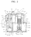
- FIG. 2 is a cross-section view of a wet dust collecting apparatus 1 cut along line II-II in FIG. 1 ;
- FIG. 3 is a front view of a grill 211' of a changed exemplary embodiment
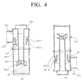
- FIG. 4 is a cross-section view of a second centrifugal separating unit B' showing a state where water overflow is prevented by a second water overflow preventing unit 600 when the wet dust collecting apparatus I in FIG. 1 is overturned;
- FIG. 5 is a view showing other exemplary embodiments of the second water overflow preventing units in FIG. 2 ;
- FIG. 6 is a schematic cross-section view showing a configuration of first separating units A', A", and A'" according to another exemplary embodiment of the first separating unit A in FIG. 2 .
- FIG. 1 is a perspective view of a wet dust collecting apparatus according to an exemplary embodiment of the present invention
- FIG. 2 is a cross-section view of the wet dust collecting apparatus 1 cut along line II - II in FIG. 1 .
- the wet dust collecting apparatus 1 includes a centrifugal separating assembly 200 and a dust container unit 300.
- the centrifugal separating assembly 200 includes a handle unit 100, a first air inlet 201, a discharge chamber 270, a division wall 250 making an upper portion inside of the dust container unit 300 as a second passage 240 and dividing a lower portion inside of the dust container unit 300 into the first centrifugal separating region 200c and a plurality of centrifugal separation regions 210c, a first centrifugal separating pipe 200a, a first discharge pipe unit 210, a passage preventing member 700, a plurality of second centrifugal separating pipes 210a connecting to the discharge chamber 270, a plurality of second inlet pipe units 230, and a second water overflow preventing units 600.
- the handle unit 100 is formed on the centrifugal separating assembly 200 and may move the centrifugal separating assembly 200 or mount the centrifugal separating assembly 200 on the dust container unit 300 so that the centrifugal separating assembly 200 may be fixable or detachable. If the handle unit 100 is located on a point where a couple of the centrifugal separating assembly 200 and the dust container unit 300 is fixed, the handle unit 100 is fixed in order that a handle 101 may not rotated by a holder 150.
- the first air inlet 201 is formed on one side of the centrifugal separating assembly 200 in order that outer air inlet from like a brush assembly (not illustrated) of a vacuum cleaner may be inlet to the first centrifugal separating region 200c.
- the discharge chamber 270 covers the second discharge holes 252 on one side of the centrifugal separating assembly 200 where the second discharge holes 252 discharging air from the second centrifugal separating pipes 210a are formed so that the second discharge holes 252 may be located inside of the centrifugal separating assembly 200.
- the discharge chamber 270 collects air discharged via the second discharge holes 252 and discharges the air to a fan motor unit (not illustrated) of a vacuum cleaner (not illustrated).
- the division wall 250 includes a first discharge pipe 202 connected to the first discharge pipe unit 210 and the plurality of the second air inlets 231 connected to the plurality of the second inlet pipe units 230 are formed on a bottom surface of the division wall 250.
- the division wall 250 is disposed in a horizontal line inside of an upper portion of the centrifugal separating assembly 200 and divides the region of the centrifugal separating assembly 200 into a second passage 240 of an upper portion of the region of the centrifugal separating assembly 200 and a first centrifugal separating region 200c and a plurality of second centrifugal separating regions 210c of a lower portion of the region of the centrifugal separating assembly 200.
- the second passage 240 formed by the division wall 250 inlets air discharged from the first discharge pipe 202 to the plurality of the second centrifugal separating regions 210c via the plurality of second air inlets 231 and the second inlet pipe unit 230.
- the first centrifugal separating pipe 200a is formed as a pipe limiting the first centrifugal separating region 200c separating large and heavy dust from outer air inlet via the first air inlet 201.
- a vertical section of the first centrifugal separating pipe 200a may have a variety of shapes such as a square shape, trapezoidal shape, or an inverted trapezoidal shape.
- the first centrifugal separating pipe 200a is disposed on a bottom surface of the division wall 250 in order that the first discharge pipe 202 and the upper portion of the first centrifugal separating pipe 200a may be connected.
- a first water overflow preventing unit 202a caved in from the wpipe bottom surface is formed on a bottom surface of the first centrifugal separating pipe 200a.
- the fist discharge pipe unit 210 is formed as a cylinder shape and includes a guide 203, a grill 211, and a sealing member 220.
- the guide 203 is protruded in a spiral shape on an upper outer circumference of the first discharge pipe unit 210 and guides rotation of inlet air.
- the grill 211 has a plurality of discharge pipes 211a formed in order to filter out dust included in discharge discharged via the first discharge pipe unit 210 and is formed on a center of the first discharge pipe unit 210.
- the sealing member 220 is coupled to a bottom surface of the first discharge pipe unit 210.
- the first discharge pipe unit 210 is coupled to the bottom surface of the division wall 250 in order to be connected to the second passage 240 via the first discharge pipe 202 within the first centrifugal separating pipe 200a, thereby being connected to the centrifugal separating assembly 200.
- the sealing member 220 When the centrifugal separating assembly 200 where the first discharge pipe unit 210 is coupled is connected to the dust container unit 300, the sealing member 220 is coupled to the water discharge pipe 501 of the water discharge passage unit 500. Accordingly, the sealing member 220 divides the water discharge passage unit 500 and the first wet type dust collecting region 300c.
- the passage preventing member 700 is installed inside of the first discharge pipe unit 210 to prevent water W from being inlet inside of a vacuum cleaner (not illustrated) via the first discharge pipe unit 210.
- Each of the plurality of second centrifugal separating pipes 210a has a cylinder shape.
- the second discharge holes 252 connected to the discharge chamber 270 is formed respectively on one side of an upper portion of each of the second centrifugal separating pipes 210a.
- the plurality of the second centrifugal separating pipes 210a have smaller inside diameter than the first centrifugal separating pipe 200a in order to separate fine dust not separated from the first centrifugal separating pipe 200a.
- the second centrifugal separating pipes 210a are coupled to the bottom surface of the division wall 250 in order to include the second air inlet 231.
- the second centrifugal separating pipes 210a limit the second centrifugal separating region 210c
- the plurality of the second centrifugal separating pipes 210a are disposed on a side of the first centrifugal separating pipe 200a and have an integrated shape.
- the second inlet pipe units 230 are formed as a cylinder shape and opened in an upper and a bottom portion of the second inlet pipe units 230.
- the second inlet pipe units 230 include an impeller 235 having an impeller rib 235a curved at a predetermined angle with a plurality of holes are formed on the bottom region of the second inlet pipe units 230.
- the second inlet pipe units 230 are coupled to the bottom surface of the division wall 250 in order to connect to the second passage 240 via the second air inlet 231 inside of each of the second centrifugal separating regions 210c, and the second inlet pipe units 230 are disposed respectively on a center portion of the cylinder shape second centrifugal separating pipes 210a.
- the impeller 235 When the second inlet pipe units 230 are disposed respectively on the center portion of the second centrifugal separating pipes 210a, at least a part of the impeller 235 is sunk in a center portion of water W filled inside of the second centrifugal separating region 210c. A level of the impeller 235 and depth of water may be verified. That is, the impeller 235 may be disposed to be completely or partly underwater. In addition, the bottom portion of the impeller 235 may be disposed to contact with surface of water W or a little bit detached to the surface of water.
- the impeller 235 is underwater or disposed on the surface of water to increase a surface contacting with water to separate fine dust by contacting air discharged via the impeller 235 with water directly and rotating the air, and to transmit a suction force generated from a suction motor (not illustrated) to the first centrifugal separating region 200c via the impeller 235 efficiently.
- the impeller 235 makes air discharged via the second inlet pipe units 230 move to a lower portion of a center of the second inlet pipe units 230 and be rotated and disposed on around the center of the second inlet pipe units 230. Accordingly, the air of the second centrifugal separating region 210c is contacted with water of the second wet type dust collecting region 310c so that dust is separated and air and water is rotated.
- the second water overflow preventing unit 600 includes a plurality of water overflow preventing ribs 601a and 601a' forming a concentric circle and having a cylinder shape toward a lower direction.
- the second water overflow preventing unit 600 has a shape having larger inside diameter than an external diameter of the second inlet pipe unit 230 and an external diameter corresponding to an inside diameter of the second centrifugal separating pipe 210a.
- the water overflow preventing unit 600 is inserted into an outer circumference of the second inlet pipe units 230 to form a second discharge passage 602. Then, the second water overflow preventing unit 600 is located on a bottom portion of the second discharge holes 252 and fixed inside of the second centrifugal separation pipes 210a.
- the dust container 300 (see FIG. 2 ) includes a first dust container 300a, a plurality of the second dust containers 310a, and a sub-cover 400 forming a water discharge passage unit 500 connecting bottom surfaces of the first dust container 300a and the second dust container 310a.
- the first dust container 300a includes the first wet type dust collecting region 300c collecting dust with rotating water W.
- a vertical cross-section of the first dust container 300a may have a variety of shapes such as a rectangular shape, trapezoidal shape, and an inverted trapezoidal shape.
- the second dust containers 310a form a plurality of the second wet type dust collecting regions 310c collecting dust with rotating water W.
- the second dust containers 310a forming the second wet type dust collecting regions 310c are formed in a line along a side of the first dust container 300a on a location facing a bottom surface of each of the second centrifugal separating pipes 210a.
- a bottom surface of the first wet type dust collecting region 300c and a bottom surface of the second wet type dust collecting regions 310c are connected from each other via the a water discharge passage unit 500.
- a configuration of the water discharge passage unit 500 is not a feature of the present invention, so the specific description thereof is omitted.
- the centrifugal separating assembly 200 forms the wet type dust collecting apparatus I by being connected to an upper portion of the dust container unit 300.
- the centrifugal separating assembly 200 When the centrifugal separating assembly 200 is coupled to an upper portion of the dust container 300, the first centrifugal separating pipe 200a is inserted into an inside of the first dust container 300a. At this time, the sealing member 220 separates the water discharge passage unit 500 and the first wet type dust collecting region 300c by being coupled to the water discharge pipe 501.
- the first water overflow preventing unit 202a is protruded in a lower direction from a bottom surface of the first centrifugal separating pipe 200a and prevents water W rotating inside of the first wet type dust collecting region 300c formed by the first dust container 300a from being overflew on the grill 211. Accordingly, it is prevented that the water W filled in the first wet type dust collecting region 300c is inlet to the second passage 240 or the second centrifugal separating unit B'.
- the first water overflow preventing unit 202a may be protruded toward inside of the first wet type dust collecting region 300c on an upper surface of the first dust container 300a.
- the second inlet pipe units 230 are also inserted into the second centrifugal separating pipes 210a facing the second inlet pipe units 230 respectively.
- the centrifugal separating assembly 200 When the centrifugal separating assembly 200 is coupled to the dust container unit 300, the first centrifugal separating pipe 200a and the first dust container 300a which are coupled from each other form the first separating unit A.
- each of second centrifugal separating pipe 210a and second dust containers 310a form a second centrifugal separating unit B' respectively.
- Each of the second centrifugal separating units B' separates fine dust not separated in the first separating unit A respectively.
- All of the second centrifugal separating units B' form the second separating unit B separating dust such as fine dust not separated in the first separating unit A.
- the fixing unit 104 and hook unit 105 are coupled from each other so that the centrifugal separating assembly 200 and the dust container unit 300 may not be separated from each other.
- the discharge chamber 270 is coupled to a passage connected to a fan motor unit (not illustrated) of the vacuum cleaner (not illustrated).
- the first air inlet 201 is coupled to an inlet passage (not illustrated) connected to a brush assembly body (not illustrated). Accordingly, the wet type dust collecting apparatus 1 forms a passage for air flow inside of a vacuum cleaner (not illustrated).
- air inlet from an outside is inlet to the first centrifugal separating region 200c via the first air inlet 201.
- the air inlet inside of the first centrifugal separating region 200c rotates around the first discharge pipe unit 210.
- water W filled in the first wet type dust collecting region 300c of the fist dust container 300a by rotation force of the air is also rotated. Accordingly, dust is filtered out in the first centrifugal separating region 200c by centrifugal force, and dust filtered out by rotating water W is collected in the first wet type dust collecting region 300c.
- the first water overflow preventing unit 202a and a raised spot 2 block out water W of the first dust container 300a to be inlet to the grill 211.
- Water overflow in the wet type dust collecting apparatus 1 may be minimized by the first water overflow preventing unit 202a and the raised spot 2.
- the air where dust is filtered out by rotating water W and centrifugal force generated by air rotation in the first separating unit A is inlet to the second passage 240 via the grill 211 and the first discharge pipe unit 210.
- the air inlet via the second passage 240 is inlet to the second wet type dust collecting regions 310c via the plurality of second air inlets 231 formed on the division wall 250 and the second centrifugal separating pipes 210a connected to the second air inlets 231.
- air inlet to the second wet type dust collecting regions 310c is discharged to be rotated in one direction by the impeller 235. Accordingly, water W filled in the second wet type dust collecting regions 310c is rotated. Water W rotating in the second wet type dust collecting regions 310c collects dust with its own viscosity and polarity and apply centrifugal force to fine dust included in the air discharged in the water W, thereby enhancing efficiency of filtration and collection of fine dust.
- the second water overflow prevention units 600 prevents droplets generated from the water W rising along an interior wall of the second centrifugal separating pipes 210a by rotation or the water W rotating in the second centrifugal separating regions 210c from being disposed toward an outside via the second discharge passages 602.
- FIG, 4 is a cross-section view of the second centrifugal separating unit B' showing a state where water overflow is prevented by the second water overflow preventing units 600 when the wet type dust collecting apparatus 1 of FIG. 1 is overturned.
- (a) of FIG. 4 is a cross-section view of the second centrifugal separating unit B' in a normal state
- (b) of FIG. 4 is a cross-section view of the second centrifugal separating unit B' in an overturned state.
- water W outlet to an outside is prevented by the water overflow preventing ribs 601 a and 601a' of the second water overflow preventing units 600.
- FIG. 5 is a view showing other exemplary embodiments of the second water overflow preventing units 600 of FIG. 2 .
- the second water overflow preventing units 600 may have diverse configurations such as having double water overflow preventing ribs 601 a and 601 a' as illustrated in (a) of FIG. 5 , having single water overflow preventing rib 601b as illustrated in (b) of FIG. 5 , and a trapezoidal shape of a vertical section as illustrated in (c) of FIG. 5 .
- FIG. 6 is a schematic view showing a configuration of a first separating unit A', A", and A"' according to another exemplary embodiment of the first separating unit A in FIG. 2 .
- the first separating unit A in FIG. 2 may include the first centrifugal separating unit A' formed of the first centrifugal separating pipe 200a' having a trapezoidal shape whose lower portion of a vertical cross section is narrow, a first centrifugal separating unit A" formed of a first dust container 300a' having a trapezoidal shape whose lower portion of a vertical cross section is narrow as (b) of FIG. 6 , and a first separating unit A' " formed of a first centrifugal separating pipe 200a' having a trapezoidal shape whose lower portion of a vertical cross section is narrow as (c) of FIG. 6 , and a first dust container 300a'.
- dust separating efficiency of the first separating unit A' in (a) of FIG. 6 may be increased.
- a mixing degree of water and dust of the first separating unit A" in (b) of FIG. 6 may be increased.
- Dust separating efficiency and mixing degree of water and dust of the first separating unit A' " in (c) of FIG. 6 may be also increased.
- a horizontal cross-section of the first centrifugal separating pipe 200a disposed on an upper portion of the first dust container 300a collecting dust separated by rotating water smaller horizontal cross section is smaller than a horizontal cross section of the first dust container 300a.
- the wet type dust collecting apparatus 1 enhances a problem of a case where if an internal diameter of a centrifugal separating pipe of a wet type dust collecting apparatus of a conventional technology to separate dust by using centrifugal force of the configuration and operation as described above increases, dust separating efficiency increases and quantity of water W overflow also increases.
- the wet type dust collecting apparatus 1 makes a horizontal cross-section of the first centrifugal separating pipe 200a small and enhance rotating force of air (increase centrifugal force), thereby enhancing dust separating efficiency.
- the wet type dust collecting apparatus I increases a surface area of water by increasing a cross section of the first dust container 300a.
- dust separating efficiency is increased as probability of contact of water and dust is increased and accordingly, overall separating efficiency of the wet type dust collecting apparatus 1 is enhanced.
- the wet type dust collecting apparatus 1 makes a horizontal cross section of the first centrifugal separating pipe 200a smaller than a horizontal cross section of the first dust container 300a. Accordingly, water W inlet from the first wet type dust collecting region 300c to the first centrifugal separating region 200c may be prevented by the raised spot 2 which has a predetermined width and is formed on a connecting unit of the first centrifugal separating pipe 200a and the second dust containers 310a.
- the first water overflow preventing unit 202a is formed on a bottom surface of the first centrifugal separating pipe 200a. Accordingly, a case where water rotating inside of the first dust container 300a is inlet inside of the first centrifugal separating region 200c may be further prevented.
- the wet type dust collecting apparatus 1 having the above described configuration and functions operates in a dry type dust collecting apparatus when water W is not filled in the wet type dust collecting apparatus 1.
- the present invention may be applied to cleaning apparatuses for home, business, and industry.
Landscapes
- Engineering & Computer Science (AREA)
- Mechanical Engineering (AREA)
- Filters For Electric Vacuum Cleaners (AREA)
Applications Claiming Priority (2)
| Application Number | Priority Date | Filing Date | Title |
|---|---|---|---|
| KR1020090079415A KR20110021552A (ko) | 2009-08-26 | 2009-08-26 | 진공청소기의 습식집진장치 |
| PCT/KR2010/003788 WO2011025130A2 (fr) | 2009-08-26 | 2010-06-11 | Collecteur de poussière de type humide pour aspirateur |
Publications (3)
| Publication Number | Publication Date |
|---|---|
| EP2471430A2 true EP2471430A2 (fr) | 2012-07-04 |
| EP2471430A4 EP2471430A4 (fr) | 2013-05-22 |
| EP2471430B1 EP2471430B1 (fr) | 2015-04-01 |
Family
ID=43628515
Family Applications (1)
| Application Number | Title | Priority Date | Filing Date |
|---|---|---|---|
| EP10812145.0A Active EP2471430B1 (fr) | 2009-08-26 | 2010-06-11 | Collecteur de poussière de type humide pour aspirateur |
Country Status (4)
| Country | Link |
|---|---|
| US (1) | US8728222B2 (fr) |
| EP (1) | EP2471430B1 (fr) |
| KR (1) | KR20110021552A (fr) |
| WO (1) | WO2011025130A2 (fr) |
Cited By (1)
| Publication number | Priority date | Publication date | Assignee | Title |
|---|---|---|---|---|
| RU2704546C2 (ru) * | 2015-04-13 | 2019-10-29 | Конинклейке Филипс Н.В. | Безмешковый пылесос |
Families Citing this family (6)
| Publication number | Priority date | Publication date | Assignee | Title |
|---|---|---|---|---|
| WO2014020573A2 (fr) * | 2012-08-02 | 2014-02-06 | Talentone Hong Kong Ltd. | Aspirateurs et filtres à poussière humides |
| US9604343B2 (en) | 2014-09-19 | 2017-03-28 | Daniel P Oksanen | Hydro-filtration unit with sanding heads |
| US9883782B2 (en) | 2014-10-16 | 2018-02-06 | Intelliclean Solutions, Llc | Liquid filtration vacuum |
| US9782049B2 (en) | 2014-10-16 | 2017-10-10 | Intelliclean Solutions, Llc | Liquid filtration vacuum |
| DE102017208969A1 (de) * | 2017-05-29 | 2018-11-29 | BSH Hausgeräte GmbH | Anordnung zum Verriegeln einer Staubabscheideeinheit |
| KR102212071B1 (ko) * | 2018-08-20 | 2021-02-03 | 순천향대학교 산학협력단 | 척추 수술중 자가 골가루 채집기 |
Family Cites Families (9)
| Publication number | Priority date | Publication date | Assignee | Title |
|---|---|---|---|---|
| JPH07116096A (ja) | 1993-10-21 | 1995-05-09 | Akai Electric Co Ltd | 電気掃除機 |
| PT768058E (pt) * | 1995-10-13 | 2000-10-31 | T P A Impex Spa | Maquina melhorada para a limpeza dom+estica |
| US7370389B2 (en) * | 2004-11-24 | 2008-05-13 | Samson Tsen | Water filter vacuum cleaner |
| KR101053378B1 (ko) * | 2005-03-19 | 2011-08-01 | 엘지전자 주식회사 | 물청소 겸용 진공청소기의 집진유니트 |
| KR100704336B1 (ko) | 2005-07-19 | 2007-04-10 | 전치문 | 진공청소기용 사이클론 집진장치 |
| AU2006220438B2 (en) | 2005-09-23 | 2011-02-03 | Bissell Inc. | Vacuum cleaner with two stage filtration |
| JP2007111397A (ja) * | 2005-10-24 | 2007-05-10 | Izumi Products Co | 湿式電気掃除機 |
| KR100800655B1 (ko) * | 2006-07-04 | 2008-02-01 | 김종기 | 건식 및 습식 이중필터방식 진공청소기 |
| US7779505B2 (en) * | 2007-03-09 | 2010-08-24 | Bissell Homecare, Inc. | Wet/dry vacuum cleaner |
-
2009
- 2009-08-26 KR KR1020090079415A patent/KR20110021552A/ko not_active Ceased
-
2010
- 2010-06-11 WO PCT/KR2010/003788 patent/WO2011025130A2/fr not_active Ceased
- 2010-06-11 EP EP10812145.0A patent/EP2471430B1/fr active Active
-
2012
- 2012-02-22 US US13/401,954 patent/US8728222B2/en active Active
Cited By (1)
| Publication number | Priority date | Publication date | Assignee | Title |
|---|---|---|---|---|
| RU2704546C2 (ru) * | 2015-04-13 | 2019-10-29 | Конинклейке Филипс Н.В. | Безмешковый пылесос |
Also Published As
| Publication number | Publication date |
|---|---|
| WO2011025130A3 (fr) | 2011-04-21 |
| EP2471430B1 (fr) | 2015-04-01 |
| WO2011025130A2 (fr) | 2011-03-03 |
| EP2471430A4 (fr) | 2013-05-22 |
| US20120145009A1 (en) | 2012-06-14 |
| US8728222B2 (en) | 2014-05-20 |
| KR20110021552A (ko) | 2011-03-04 |
Similar Documents
| Publication | Publication Date | Title |
|---|---|---|
| EP2471430B1 (fr) | Collecteur de poussière de type humide pour aspirateur | |
| EP3453298B1 (fr) | Aspirateur | |
| JP2721280B2 (ja) | 真空清掃機 | |
| KR102000611B1 (ko) | 진공 청소기 | |
| AU2017261074B2 (en) | Vacuum cleaner | |
| JP2007275591A (ja) | 真空掃除機の集塵装置 | |
| KR20160089201A (ko) | 진공 청소기용 집진장치 | |
| RU2004120671A (ru) | Узел электродвигателя (варианты) и пылесос с таким узлом | |
| CN1883356A (zh) | 用于湿式真空吸尘器的旋风集尘装置 | |
| CN1977747A (zh) | 湿式电动吸尘器 | |
| KR20190007293A (ko) | 진공 청소기 | |
| EP2471431B1 (fr) | Collecteur de poussière de type humide pour aspirateur | |
| KR100606842B1 (ko) | 다중 사이클론 집진장치 | |
| KR20100104792A (ko) | 분리형 원심분리기와 먼지통을 구비한 진공청소기의 집진장치 | |
| JPH04288111A (ja) | 電気掃除機 | |
| CN114052599A (zh) | 污水箱及洗地机 | |
| JP6212451B2 (ja) | 集塵装置、及び電気掃除機 | |
| CN220937953U (zh) | 清洁设备 | |
| JP6437609B2 (ja) | 集塵装置、及び電気掃除機 | |
| CN101889843A (zh) | 灰尘分离及自清洁式集尘桶 | |
| CN212307699U (zh) | 一种具有水气分离结构的吸水刷 | |
| CN1951305A (zh) | 集尘装置 | |
| CN219089081U (zh) | 尘杯组件及清洁设备 | |
| KR101984569B1 (ko) | 집진장치 및 이를 포함하는 진공청소기 | |
| KR20150127816A (ko) | 집진 유닛 및 이를 구비한 진공 청소기 |
Legal Events
| Date | Code | Title | Description |
|---|---|---|---|
| PUAI | Public reference made under article 153(3) epc to a published international application that has entered the european phase |
Free format text: ORIGINAL CODE: 0009012 |
|
| 17P | Request for examination filed |
Effective date: 20120308 |
|
| AK | Designated contracting states |
Kind code of ref document: A2 Designated state(s): AL AT BE BG CH CY CZ DE DK EE ES FI FR GB GR HR HU IE IS IT LI LT LU LV MC MK MT NL NO PL PT RO SE SI SK SM TR |
|
| RAP1 | Party data changed (applicant data changed or rights of an application transferred) |
Owner name: SAMSUNG ELECTRONICS CO., LTD. |
|
| DAX | Request for extension of the european patent (deleted) | ||
| A4 | Supplementary search report drawn up and despatched |
Effective date: 20130418 |
|
| RIC1 | Information provided on ipc code assigned before grant |
Ipc: A47L 9/16 20060101ALI20130412BHEP Ipc: A47L 9/18 20060101AFI20130412BHEP |
|
| GRAP | Despatch of communication of intention to grant a patent |
Free format text: ORIGINAL CODE: EPIDOSNIGR1 |
|
| INTG | Intention to grant announced |
Effective date: 20141104 |
|
| GRAS | Grant fee paid |
Free format text: ORIGINAL CODE: EPIDOSNIGR3 |
|
| GRAA | (expected) grant |
Free format text: ORIGINAL CODE: 0009210 |
|
| AK | Designated contracting states |
Kind code of ref document: B1 Designated state(s): AL AT BE BG CH CY CZ DE DK EE ES FI FR GB GR HR HU IE IS IT LI LT LU LV MC MK MT NL NO PL PT RO SE SI SK SM TR |
|
| REG | Reference to a national code |
Ref country code: GB Ref legal event code: FG4D |
|
| REG | Reference to a national code |
Ref country code: CH Ref legal event code: EP |
|
| REG | Reference to a national code |
Ref country code: IE Ref legal event code: FG4D |
|
| REG | Reference to a national code |
Ref country code: AT Ref legal event code: REF Ref document number: 718591 Country of ref document: AT Kind code of ref document: T Effective date: 20150515 |
|
| REG | Reference to a national code |
Ref country code: DE Ref legal event code: R096 Ref document number: 602010023656 Country of ref document: DE Effective date: 20150521 |
|
| REG | Reference to a national code |
Ref country code: NL Ref legal event code: VDEP Effective date: 20150401 |
|
| REG | Reference to a national code |
Ref country code: AT Ref legal event code: MK05 Ref document number: 718591 Country of ref document: AT Kind code of ref document: T Effective date: 20150401 |
|
| REG | Reference to a national code |
Ref country code: LT Ref legal event code: MG4D |
|
| PG25 | Lapsed in a contracting state [announced via postgrant information from national office to epo] |
Ref country code: NL Free format text: LAPSE BECAUSE OF FAILURE TO SUBMIT A TRANSLATION OF THE DESCRIPTION OR TO PAY THE FEE WITHIN THE PRESCRIBED TIME-LIMIT Effective date: 20150401 |
|
| PG25 | Lapsed in a contracting state [announced via postgrant information from national office to epo] |
Ref country code: PT Free format text: LAPSE BECAUSE OF FAILURE TO SUBMIT A TRANSLATION OF THE DESCRIPTION OR TO PAY THE FEE WITHIN THE PRESCRIBED TIME-LIMIT Effective date: 20150803 Ref country code: NO Free format text: LAPSE BECAUSE OF FAILURE TO SUBMIT A TRANSLATION OF THE DESCRIPTION OR TO PAY THE FEE WITHIN THE PRESCRIBED TIME-LIMIT Effective date: 20150701 Ref country code: ES Free format text: LAPSE BECAUSE OF FAILURE TO SUBMIT A TRANSLATION OF THE DESCRIPTION OR TO PAY THE FEE WITHIN THE PRESCRIBED TIME-LIMIT Effective date: 20150401 Ref country code: HR Free format text: LAPSE BECAUSE OF FAILURE TO SUBMIT A TRANSLATION OF THE DESCRIPTION OR TO PAY THE FEE WITHIN THE PRESCRIBED TIME-LIMIT Effective date: 20150401 Ref country code: FI Free format text: LAPSE BECAUSE OF FAILURE TO SUBMIT A TRANSLATION OF THE DESCRIPTION OR TO PAY THE FEE WITHIN THE PRESCRIBED TIME-LIMIT Effective date: 20150401 Ref country code: CZ Free format text: LAPSE BECAUSE OF FAILURE TO SUBMIT A TRANSLATION OF THE DESCRIPTION OR TO PAY THE FEE WITHIN THE PRESCRIBED TIME-LIMIT Effective date: 20150401 Ref country code: LT Free format text: LAPSE BECAUSE OF FAILURE TO SUBMIT A TRANSLATION OF THE DESCRIPTION OR TO PAY THE FEE WITHIN THE PRESCRIBED TIME-LIMIT Effective date: 20150401 |
|
| PG25 | Lapsed in a contracting state [announced via postgrant information from national office to epo] |
Ref country code: GR Free format text: LAPSE BECAUSE OF FAILURE TO SUBMIT A TRANSLATION OF THE DESCRIPTION OR TO PAY THE FEE WITHIN THE PRESCRIBED TIME-LIMIT Effective date: 20150702 Ref country code: AT Free format text: LAPSE BECAUSE OF FAILURE TO SUBMIT A TRANSLATION OF THE DESCRIPTION OR TO PAY THE FEE WITHIN THE PRESCRIBED TIME-LIMIT Effective date: 20150401 Ref country code: IS Free format text: LAPSE BECAUSE OF FAILURE TO SUBMIT A TRANSLATION OF THE DESCRIPTION OR TO PAY THE FEE WITHIN THE PRESCRIBED TIME-LIMIT Effective date: 20150801 Ref country code: LV Free format text: LAPSE BECAUSE OF FAILURE TO SUBMIT A TRANSLATION OF THE DESCRIPTION OR TO PAY THE FEE WITHIN THE PRESCRIBED TIME-LIMIT Effective date: 20150401 |
|
| REG | Reference to a national code |
Ref country code: DE Ref legal event code: R097 Ref document number: 602010023656 Country of ref document: DE |
|
| PG25 | Lapsed in a contracting state [announced via postgrant information from national office to epo] |
Ref country code: EE Free format text: LAPSE BECAUSE OF FAILURE TO SUBMIT A TRANSLATION OF THE DESCRIPTION OR TO PAY THE FEE WITHIN THE PRESCRIBED TIME-LIMIT Effective date: 20150401 Ref country code: DK Free format text: LAPSE BECAUSE OF FAILURE TO SUBMIT A TRANSLATION OF THE DESCRIPTION OR TO PAY THE FEE WITHIN THE PRESCRIBED TIME-LIMIT Effective date: 20150401 Ref country code: MC Free format text: LAPSE BECAUSE OF FAILURE TO SUBMIT A TRANSLATION OF THE DESCRIPTION OR TO PAY THE FEE WITHIN THE PRESCRIBED TIME-LIMIT Effective date: 20150401 Ref country code: IT Free format text: LAPSE BECAUSE OF NON-PAYMENT OF DUE FEES Effective date: 20150611 |
|
| REG | Reference to a national code |
Ref country code: CH Ref legal event code: PL |
|
| PLBE | No opposition filed within time limit |
Free format text: ORIGINAL CODE: 0009261 |
|
| STAA | Information on the status of an ep patent application or granted ep patent |
Free format text: STATUS: NO OPPOSITION FILED WITHIN TIME LIMIT |
|
| PG25 | Lapsed in a contracting state [announced via postgrant information from national office to epo] |
Ref country code: RO Free format text: LAPSE BECAUSE OF NON-PAYMENT OF DUE FEES Effective date: 20150401 Ref country code: LU Free format text: LAPSE BECAUSE OF FAILURE TO SUBMIT A TRANSLATION OF THE DESCRIPTION OR TO PAY THE FEE WITHIN THE PRESCRIBED TIME-LIMIT Effective date: 20150611 Ref country code: SK Free format text: LAPSE BECAUSE OF FAILURE TO SUBMIT A TRANSLATION OF THE DESCRIPTION OR TO PAY THE FEE WITHIN THE PRESCRIBED TIME-LIMIT Effective date: 20150401 Ref country code: PL Free format text: LAPSE BECAUSE OF FAILURE TO SUBMIT A TRANSLATION OF THE DESCRIPTION OR TO PAY THE FEE WITHIN THE PRESCRIBED TIME-LIMIT Effective date: 20150401 |
|
| 26N | No opposition filed |
Effective date: 20160105 |
|
| REG | Reference to a national code |
Ref country code: IE Ref legal event code: MM4A |
|
| PG25 | Lapsed in a contracting state [announced via postgrant information from national office to epo] |
Ref country code: LI Free format text: LAPSE BECAUSE OF NON-PAYMENT OF DUE FEES Effective date: 20150630 Ref country code: CH Free format text: LAPSE BECAUSE OF NON-PAYMENT OF DUE FEES Effective date: 20150630 Ref country code: IE Free format text: LAPSE BECAUSE OF NON-PAYMENT OF DUE FEES Effective date: 20150611 |
|
| PGRI | Patent reinstated in contracting state [announced from national office to epo] |
Ref country code: IT Effective date: 20160412 |
|
| REG | Reference to a national code |
Ref country code: FR Ref legal event code: PLFP Year of fee payment: 7 |
|
| PG25 | Lapsed in a contracting state [announced via postgrant information from national office to epo] |
Ref country code: SI Free format text: LAPSE BECAUSE OF FAILURE TO SUBMIT A TRANSLATION OF THE DESCRIPTION OR TO PAY THE FEE WITHIN THE PRESCRIBED TIME-LIMIT Effective date: 20150401 |
|
| PG25 | Lapsed in a contracting state [announced via postgrant information from national office to epo] |
Ref country code: BE Free format text: LAPSE BECAUSE OF FAILURE TO SUBMIT A TRANSLATION OF THE DESCRIPTION OR TO PAY THE FEE WITHIN THE PRESCRIBED TIME-LIMIT Effective date: 20150401 |
|
| PG25 | Lapsed in a contracting state [announced via postgrant information from national office to epo] |
Ref country code: MT Free format text: LAPSE BECAUSE OF FAILURE TO SUBMIT A TRANSLATION OF THE DESCRIPTION OR TO PAY THE FEE WITHIN THE PRESCRIBED TIME-LIMIT Effective date: 20150401 |
|
| REG | Reference to a national code |
Ref country code: FR Ref legal event code: PLFP Year of fee payment: 8 |
|
| PG25 | Lapsed in a contracting state [announced via postgrant information from national office to epo] |
Ref country code: BG Free format text: LAPSE BECAUSE OF FAILURE TO SUBMIT A TRANSLATION OF THE DESCRIPTION OR TO PAY THE FEE WITHIN THE PRESCRIBED TIME-LIMIT Effective date: 20150401 Ref country code: HU Free format text: LAPSE BECAUSE OF FAILURE TO SUBMIT A TRANSLATION OF THE DESCRIPTION OR TO PAY THE FEE WITHIN THE PRESCRIBED TIME-LIMIT; INVALID AB INITIO Effective date: 20100611 Ref country code: SM Free format text: LAPSE BECAUSE OF FAILURE TO SUBMIT A TRANSLATION OF THE DESCRIPTION OR TO PAY THE FEE WITHIN THE PRESCRIBED TIME-LIMIT Effective date: 20150401 |
|
| PG25 | Lapsed in a contracting state [announced via postgrant information from national office to epo] |
Ref country code: CY Free format text: LAPSE BECAUSE OF FAILURE TO SUBMIT A TRANSLATION OF THE DESCRIPTION OR TO PAY THE FEE WITHIN THE PRESCRIBED TIME-LIMIT Effective date: 20150401 Ref country code: SE Free format text: LAPSE BECAUSE OF FAILURE TO SUBMIT A TRANSLATION OF THE DESCRIPTION OR TO PAY THE FEE WITHIN THE PRESCRIBED TIME-LIMIT Effective date: 20150401 |
|
| PG25 | Lapsed in a contracting state [announced via postgrant information from national office to epo] |
Ref country code: TR Free format text: LAPSE BECAUSE OF FAILURE TO SUBMIT A TRANSLATION OF THE DESCRIPTION OR TO PAY THE FEE WITHIN THE PRESCRIBED TIME-LIMIT Effective date: 20150401 |
|
| REG | Reference to a national code |
Ref country code: FR Ref legal event code: PLFP Year of fee payment: 9 |
|
| PG25 | Lapsed in a contracting state [announced via postgrant information from national office to epo] |
Ref country code: MK Free format text: LAPSE BECAUSE OF FAILURE TO SUBMIT A TRANSLATION OF THE DESCRIPTION OR TO PAY THE FEE WITHIN THE PRESCRIBED TIME-LIMIT Effective date: 20150401 |
|
| PG25 | Lapsed in a contracting state [announced via postgrant information from national office to epo] |
Ref country code: AL Free format text: LAPSE BECAUSE OF FAILURE TO SUBMIT A TRANSLATION OF THE DESCRIPTION OR TO PAY THE FEE WITHIN THE PRESCRIBED TIME-LIMIT Effective date: 20150401 |
|
| PGFP | Annual fee paid to national office [announced via postgrant information from national office to epo] |
Ref country code: IT Payment date: 20220523 Year of fee payment: 13 Ref country code: FR Payment date: 20220527 Year of fee payment: 13 |
|
| PG25 | Lapsed in a contracting state [announced via postgrant information from national office to epo] |
Ref country code: FR Free format text: LAPSE BECAUSE OF NON-PAYMENT OF DUE FEES Effective date: 20230630 |
|
| PGFP | Annual fee paid to national office [announced via postgrant information from national office to epo] |
Ref country code: DE Payment date: 20250520 Year of fee payment: 16 |
|
| PGFP | Annual fee paid to national office [announced via postgrant information from national office to epo] |
Ref country code: GB Payment date: 20250520 Year of fee payment: 16 |
|
| PG25 | Lapsed in a contracting state [announced via postgrant information from national office to epo] |
Ref country code: IT Free format text: LAPSE BECAUSE OF NON-PAYMENT OF DUE FEES Effective date: 20230611 |