EP2471706A1 - Rettungsring - Google Patents
Rettungsring Download PDFInfo
- Publication number
- EP2471706A1 EP2471706A1 EP10812030A EP10812030A EP2471706A1 EP 2471706 A1 EP2471706 A1 EP 2471706A1 EP 10812030 A EP10812030 A EP 10812030A EP 10812030 A EP10812030 A EP 10812030A EP 2471706 A1 EP2471706 A1 EP 2471706A1
- Authority
- EP
- European Patent Office
- Prior art keywords
- preserver
- water
- preserver body
- hollow region
- air
- Prior art date
- Legal status (The legal status is an assumption and is not a legal conclusion. Google has not performed a legal analysis and makes no representation as to the accuracy of the status listed.)
- Withdrawn
Links
- XLYOFNOQVPJJNP-UHFFFAOYSA-N water Substances O XLYOFNOQVPJJNP-UHFFFAOYSA-N 0.000 claims abstract description 228
- 239000007788 liquid Substances 0.000 claims abstract description 120
- 239000004088 foaming agent Substances 0.000 claims abstract description 68
- 238000006243 chemical reaction Methods 0.000 claims abstract description 29
- 238000005187 foaming Methods 0.000 claims description 32
- 239000013535 sea water Substances 0.000 claims description 13
- 238000003825 pressing Methods 0.000 claims description 12
- 238000004891 communication Methods 0.000 claims description 3
- 239000012530 fluid Substances 0.000 abstract 1
- 239000007789 gas Substances 0.000 description 68
- CURLTUGMZLYLDI-UHFFFAOYSA-N Carbon dioxide Chemical compound O=C=O CURLTUGMZLYLDI-UHFFFAOYSA-N 0.000 description 24
- 206010013647 Drowning Diseases 0.000 description 23
- 239000000463 material Substances 0.000 description 21
- 230000009182 swimming Effects 0.000 description 17
- 239000002195 soluble material Substances 0.000 description 15
- 239000006260 foam Substances 0.000 description 13
- 239000001569 carbon dioxide Substances 0.000 description 12
- 229910002092 carbon dioxide Inorganic materials 0.000 description 12
- 229920000877 Melamine resin Polymers 0.000 description 9
- JDSHMPZPIAZGSV-UHFFFAOYSA-N melamine Chemical compound NC1=NC(N)=NC(N)=N1 JDSHMPZPIAZGSV-UHFFFAOYSA-N 0.000 description 9
- 239000002984 plastic foam Substances 0.000 description 9
- 238000007906 compression Methods 0.000 description 8
- -1 polyethylene Polymers 0.000 description 8
- 230000029058 respiratory gaseous exchange Effects 0.000 description 8
- 230000000694 effects Effects 0.000 description 7
- 238000005516 engineering process Methods 0.000 description 7
- UIIMBOGNXHQVGW-UHFFFAOYSA-M Sodium bicarbonate Chemical compound [Na+].OC([O-])=O UIIMBOGNXHQVGW-UHFFFAOYSA-M 0.000 description 6
- 230000006835 compression Effects 0.000 description 6
- 239000004698 Polyethylene Substances 0.000 description 5
- 229920000573 polyethylene Polymers 0.000 description 5
- 238000007667 floating Methods 0.000 description 4
- 229920003023 plastic Polymers 0.000 description 4
- 239000004033 plastic Substances 0.000 description 4
- 229920005989 resin Polymers 0.000 description 4
- 239000011347 resin Substances 0.000 description 4
- 239000000654 additive Substances 0.000 description 3
- KRKNYBCHXYNGOX-UHFFFAOYSA-N citric acid Chemical compound OC(=O)CC(O)(C(O)=O)CC(O)=O KRKNYBCHXYNGOX-UHFFFAOYSA-N 0.000 description 3
- 238000009413 insulation Methods 0.000 description 3
- 238000000034 method Methods 0.000 description 3
- 229920002451 polyvinyl alcohol Polymers 0.000 description 3
- 229910000030 sodium bicarbonate Inorganic materials 0.000 description 3
- 235000017557 sodium bicarbonate Nutrition 0.000 description 3
- VZCYOOQTPOCHFL-OWOJBTEDSA-N Fumaric acid Chemical compound OC(=O)\C=C\C(O)=O VZCYOOQTPOCHFL-OWOJBTEDSA-N 0.000 description 2
- MHAJPDPJQMAIIY-UHFFFAOYSA-N Hydrogen peroxide Chemical compound OO MHAJPDPJQMAIIY-UHFFFAOYSA-N 0.000 description 2
- XEEYBQQBJWHFJM-UHFFFAOYSA-N Iron Chemical compound [Fe] XEEYBQQBJWHFJM-UHFFFAOYSA-N 0.000 description 2
- 239000004372 Polyvinyl alcohol Substances 0.000 description 2
- CDBYLPFSWZWCQE-UHFFFAOYSA-L Sodium Carbonate Chemical compound [Na+].[Na+].[O-]C([O-])=O CDBYLPFSWZWCQE-UHFFFAOYSA-L 0.000 description 2
- BZHJMEDXRYGGRV-UHFFFAOYSA-N Vinyl chloride Chemical compound ClC=C BZHJMEDXRYGGRV-UHFFFAOYSA-N 0.000 description 2
- 230000000996 additive effect Effects 0.000 description 2
- 210000004712 air sac Anatomy 0.000 description 2
- QVGXLLKOCUKJST-UHFFFAOYSA-N atomic oxygen Chemical compound [O] QVGXLLKOCUKJST-UHFFFAOYSA-N 0.000 description 2
- 238000007796 conventional method Methods 0.000 description 2
- 230000003247 decreasing effect Effects 0.000 description 2
- 230000003111 delayed effect Effects 0.000 description 2
- 229920001971 elastomer Polymers 0.000 description 2
- 239000006261 foam material Substances 0.000 description 2
- 230000005484 gravity Effects 0.000 description 2
- 230000002452 interceptive effect Effects 0.000 description 2
- NUJOXMJBOLGQSY-UHFFFAOYSA-N manganese dioxide Chemical compound O=[Mn]=O NUJOXMJBOLGQSY-UHFFFAOYSA-N 0.000 description 2
- 238000004519 manufacturing process Methods 0.000 description 2
- 239000001301 oxygen Substances 0.000 description 2
- 229910052760 oxygen Inorganic materials 0.000 description 2
- 239000012466 permeate Substances 0.000 description 2
- 239000000843 powder Substances 0.000 description 2
- 239000005060 rubber Substances 0.000 description 2
- 238000007789 sealing Methods 0.000 description 2
- OYPRJOBELJOOCE-UHFFFAOYSA-N Calcium Chemical compound [Ca] OYPRJOBELJOOCE-UHFFFAOYSA-N 0.000 description 1
- 235000008733 Citrus aurantifolia Nutrition 0.000 description 1
- 229920001353 Dextrin Polymers 0.000 description 1
- 239000004375 Dextrin Substances 0.000 description 1
- FEWJPZIEWOKRBE-JCYAYHJZSA-N Dextrotartaric acid Chemical compound OC(=O)[C@H](O)[C@@H](O)C(O)=O FEWJPZIEWOKRBE-JCYAYHJZSA-N 0.000 description 1
- IMROMDMJAWUWLK-UHFFFAOYSA-N Ethenol Chemical compound OC=C IMROMDMJAWUWLK-UHFFFAOYSA-N 0.000 description 1
- 235000002678 Ipomoea batatas Nutrition 0.000 description 1
- 244000017020 Ipomoea batatas Species 0.000 description 1
- 239000004743 Polypropylene Substances 0.000 description 1
- 229920005830 Polyurethane Foam Polymers 0.000 description 1
- 235000002595 Solanum tuberosum Nutrition 0.000 description 1
- 244000061456 Solanum tuberosum Species 0.000 description 1
- 229920002472 Starch Polymers 0.000 description 1
- 229930006000 Sucrose Natural products 0.000 description 1
- FEWJPZIEWOKRBE-UHFFFAOYSA-N Tartaric acid Natural products [H+].[H+].[O-]C(=O)C(O)C(O)C([O-])=O FEWJPZIEWOKRBE-UHFFFAOYSA-N 0.000 description 1
- 235000011941 Tilia x europaea Nutrition 0.000 description 1
- HCHKCACWOHOZIP-UHFFFAOYSA-N Zinc Chemical compound [Zn] HCHKCACWOHOZIP-UHFFFAOYSA-N 0.000 description 1
- 238000009825 accumulation Methods 0.000 description 1
- 239000003570 air Substances 0.000 description 1
- XAGFODPZIPBFFR-UHFFFAOYSA-N aluminium Chemical compound [Al] XAGFODPZIPBFFR-UHFFFAOYSA-N 0.000 description 1
- 238000005452 bending Methods 0.000 description 1
- 230000036760 body temperature Effects 0.000 description 1
- 229910052791 calcium Inorganic materials 0.000 description 1
- 239000011575 calcium Substances 0.000 description 1
- 239000003054 catalyst Substances 0.000 description 1
- 239000000306 component Substances 0.000 description 1
- 230000000994 depressogenic effect Effects 0.000 description 1
- 239000002274 desiccant Substances 0.000 description 1
- 235000019425 dextrin Nutrition 0.000 description 1
- 235000014113 dietary fatty acids Nutrition 0.000 description 1
- 230000001747 exhibiting effect Effects 0.000 description 1
- 238000002474 experimental method Methods 0.000 description 1
- 239000004744 fabric Substances 0.000 description 1
- 239000000194 fatty acid Substances 0.000 description 1
- 229930195729 fatty acid Natural products 0.000 description 1
- 239000001530 fumaric acid Substances 0.000 description 1
- 150000004676 glycans Chemical class 0.000 description 1
- 229910052742 iron Inorganic materials 0.000 description 1
- 239000004571 lime Substances 0.000 description 1
- 239000000395 magnesium oxide Substances 0.000 description 1
- CPLXHLVBOLITMK-UHFFFAOYSA-N magnesium oxide Inorganic materials [Mg]=O CPLXHLVBOLITMK-UHFFFAOYSA-N 0.000 description 1
- AXZKOIWUVFPNLO-UHFFFAOYSA-N magnesium;oxygen(2-) Chemical compound [O-2].[Mg+2] AXZKOIWUVFPNLO-UHFFFAOYSA-N 0.000 description 1
- 230000007246 mechanism Effects 0.000 description 1
- 229910052751 metal Inorganic materials 0.000 description 1
- 239000002184 metal Substances 0.000 description 1
- 230000000149 penetrating effect Effects 0.000 description 1
- 239000002985 plastic film Substances 0.000 description 1
- 229920006255 plastic film Polymers 0.000 description 1
- 229940093429 polyethylene glycol 6000 Drugs 0.000 description 1
- 229920001155 polypropylene Polymers 0.000 description 1
- 229920001282 polysaccharide Polymers 0.000 description 1
- 239000005017 polysaccharide Substances 0.000 description 1
- 229920006327 polystyrene foam Polymers 0.000 description 1
- 239000011496 polyurethane foam Substances 0.000 description 1
- 235000012015 potatoes Nutrition 0.000 description 1
- 230000002441 reversible effect Effects 0.000 description 1
- 229920006395 saturated elastomer Polymers 0.000 description 1
- 235000013580 sausages Nutrition 0.000 description 1
- 229910000029 sodium carbonate Inorganic materials 0.000 description 1
- 239000008107 starch Substances 0.000 description 1
- 235000019698 starch Nutrition 0.000 description 1
- 239000008223 sterile water Substances 0.000 description 1
- 238000003860 storage Methods 0.000 description 1
- 239000000126 substance Substances 0.000 description 1
- 239000005720 sucrose Substances 0.000 description 1
- 239000011975 tartaric acid Substances 0.000 description 1
- 235000002906 tartaric acid Nutrition 0.000 description 1
- 238000012360 testing method Methods 0.000 description 1
- VZCYOOQTPOCHFL-UHFFFAOYSA-N trans-butenedioic acid Natural products OC(=O)C=CC(O)=O VZCYOOQTPOCHFL-UHFFFAOYSA-N 0.000 description 1
- 235000013311 vegetables Nutrition 0.000 description 1
- 239000011701 zinc Substances 0.000 description 1
- 229910052725 zinc Inorganic materials 0.000 description 1
Images










Classifications
-
- B—PERFORMING OPERATIONS; TRANSPORTING
- B63—SHIPS OR OTHER WATERBORNE VESSELS; RELATED EQUIPMENT
- B63C—LAUNCHING, HAULING-OUT, OR DRY-DOCKING OF VESSELS; LIFE-SAVING IN WATER; EQUIPMENT FOR DWELLING OR WORKING UNDER WATER; MEANS FOR SALVAGING OR SEARCHING FOR UNDERWATER OBJECTS
- B63C9/00—Life-saving in water
- B63C9/08—Life-buoys, e.g. rings; Life-belts, jackets, suits, or the like
- B63C9/18—Inflatable equipment characterised by the gas-generating or inflation device
-
- B—PERFORMING OPERATIONS; TRANSPORTING
- B63—SHIPS OR OTHER WATERBORNE VESSELS; RELATED EQUIPMENT
- B63C—LAUNCHING, HAULING-OUT, OR DRY-DOCKING OF VESSELS; LIFE-SAVING IN WATER; EQUIPMENT FOR DWELLING OR WORKING UNDER WATER; MEANS FOR SALVAGING OR SEARCHING FOR UNDERWATER OBJECTS
- B63C9/00—Life-saving in water
- B63C9/08—Life-buoys, e.g. rings; Life-belts, jackets, suits, or the like
- B63C9/11—Life-buoys, e.g. rings; Life-belts, jackets, suits, or the like covering the torso, e.g. harnesses
- B63C9/125—Life-buoys, e.g. rings; Life-belts, jackets, suits, or the like covering the torso, e.g. harnesses having gas-filled compartments
- B63C9/1255—Life-buoys, e.g. rings; Life-belts, jackets, suits, or the like covering the torso, e.g. harnesses having gas-filled compartments inflatable
-
- B—PERFORMING OPERATIONS; TRANSPORTING
- B63—SHIPS OR OTHER WATERBORNE VESSELS; RELATED EQUIPMENT
- B63B—SHIPS OR OTHER WATERBORNE VESSELS; EQUIPMENT FOR SHIPPING
- B63B2231/00—Material used for some parts or elements, or for particular purposes
- B63B2231/40—Synthetic materials
- B63B2231/50—Foamed synthetic materials
-
- B—PERFORMING OPERATIONS; TRANSPORTING
- B63—SHIPS OR OTHER WATERBORNE VESSELS; RELATED EQUIPMENT
- B63C—LAUNCHING, HAULING-OUT, OR DRY-DOCKING OF VESSELS; LIFE-SAVING IN WATER; EQUIPMENT FOR DWELLING OR WORKING UNDER WATER; MEANS FOR SALVAGING OR SEARCHING FOR UNDERWATER OBJECTS
- B63C9/00—Life-saving in water
- B63C9/08—Life-buoys, e.g. rings; Life-belts, jackets, suits, or the like
- B63C9/13—Life-buoys, e.g. rings; Life-belts, jackets, suits, or the like attachable to body member, e.g. arm, neck, head or waist
- B63C9/15—Life-buoys, e.g. rings; Life-belts, jackets, suits, or the like attachable to body member, e.g. arm, neck, head or waist having gas-filled compartments
- B63C9/155—Life-buoys, e.g. rings; Life-belts, jackets, suits, or the like attachable to body member, e.g. arm, neck, head or waist having gas-filled compartments inflatable
Definitions
- the present invention relates to a life preserver worn in the ocean, a lake, a river, or a pool, for example.
- Life jackets and buoyancy bags are conventional examples of life preservers that provide a body with buoyancy. If these life preservers are attached to the body, the head can be kept above water even when the arms and legs cannot move, and even in cases such as those above that can lead to drowning, the drowning victim can be kept breathing until help arrives. In this way, life jackets and buoyancy bags can be likened to seat belts used in automobiles or safety nets used for workers at high locations. Therefore, many incidents of drowning can be avoided and lives can be saved by wearing these two types of life preservers.
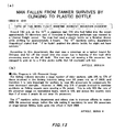
- Fig. 13(b) shows an article relating to this point. The reasons for this are thought to be as follows.
- H10-329789 shown in Table 1 the purpose of this invention is to store and manage a buoyancy applying tool, and this is completely different from the present invention, which is to help a victim during an emergency by expanding a preserver body in the water.
- This technology is already used in mattress compression bags, and in expanding preserver bodies when in the air.
- the "buoyancy applying tool" of Japanese Patent Application Publication No. H10-329789 does not expand if the air inlet is opened while in the water.
- an air inlet 2a In order to intake air while in the water, an air inlet 2a must be extended above the water surface, as in the present invention, or the air inlet 2a must be extended above the water surface by a blow tube 2 of suitable length. Accordingly, the technology of expanding and compressing the "buoyancy applying tool" of Japanese Patent Application Publication No. H10-329789 is used to store and manage the buoyancy applying tool in a compact state in the air. Therefore, combing the "buoyancy applying tool" of Japanese Patent Application Publication No. H10-329789 , the "life preserving clothing” of Japanese Utility Model Application Publication No. H3-8094 , and the "clothing" of Japanese Utility Model Application Publication No. H1-70814 would not have the same objective as the present invention, and this combination could not be used to save a life in the water, as the present invention is able to do.
- the objective of the technology described in lines 25 to 43 on page 4 of this document is to store and manage a buoyancy applying tool in a compact state.
- the technology for achieving this objective is the same as the widely known "mattress compression bag.”
- This document recites the following. "When the buoyant material is flattened and the air inlet is opened, the preserver body is filled with air due to the expansion of the buoyant material returning to an original shape due to resilient force, thereby achieving buoyancy in the preserver body" This technology is the same effect as in the widely known "mattress compression bag.”
- the objective of the life preserver of the present invention is to save a person who is drowning in water.
- the technology for saving the person in the present invention does not include using a compressed air pump to expand the life preserver. Therefore, this technology is not widely known and is not included in JP H10-329789.
- Technical Objective In order to store the buoyancy applying tool in a compact state, the preserver body is compressed and expanded while in the air. (There is absolutely no mention of expanding the preserver body while in the water.) In order to achieve buoyancy in the water, the preserver body is compressed while in the air and expanded while in the water.
- the buoyancy applying tool When in the water When the wearer wears the buoyancy applying tool and enters the water, the buoyancy applying tool is definitely in an expanded state , which creates a large amount of buoyancy in the water.
- the life preserver When the wearer wears the life preserver of the present invention, the life preserver is definitely in a thin and flat state, and does not create a large amount of buoyancy. Operation by the wearer The wearer can perform the operation of opening the air inlet/outlet while in the air many times. The wearer performs the operation of opening the inlet only during an emergency, and this operation is usually performed only once.
- Japanese Patent Application Publication No. 2000-318683 Japanese Patent Application Publication No. 2003-200887 , Japanese Examined Patent Application Publication No. 2005-502542 , Japanese Patent Application Publication No. H08-104291 , Japanese Examined Utility Model Application Publication No. S35-17626 , Japanese Examined Utility Model Application Publication No. S35-22525 , Japanese Examined Utility Model Application Publication No. S45-13562 , Japanese Utility Model Application Publication No. S62-82900 , Japanese Utility Model Application Publication No. S63-85493 , Japanese Patent Application Publication No. H07-223587 , Japanese Patent Application Publication No. H10-329789 , Japanese Utility Model Application Publication No. H3-8094, Japanese Utility Model Application Publication No. H1-70814
- the present invention has an inexpensive and simple configuration, can be worn casually by adults or children without seeming strange, enables normal swimming by not always exhibiting buoyancy when worn, and exhibits buoyancy when operated by a person during an emergency to enable breathing while waiting for rescue.
- the present invention utilizes the resilient force of an elastic member or bias member, i.e. the force to deform when pressure is added and to return to the original shape when the pressure is removed. While an extremely large amount of pressure is applied to the elastic member or the bias member in a preserver body to keep the preserver body in a thin and flat state, the pressure added to the elastic member or the bias member in the preserver body is removed during an emergency, so that resilient force accumulated in this member acts to return the member to the original shape. As a result, air or water is sucked into the preserver body.
- the volume of the preserver body increases as a result of the resilient force of the elastic member or bias member causing the return to the original shape, thereby sucking in an amount of air or water corresponding to the increased volume.
- Buoyancy increases due to the sucked-in air or gas generated as the result of a reaction between the sucked-in water and a foaming agent in order to float the body, and this buoyancy enables breathing by keeping the body afloat.
- a liquid bag is provided in the preserver body, and the liquid bag is torn as the result of pressing or pulling on the preserver body from the outside or by the resilient force obtained by releasing a bias member 3B from a latched state.
- reactive liquid sealed in the liquid bag chemically reacts with a foaming agent in the preserver body to generate gas, and the generated gas increases the buoyancy to float the body and enable breathing.
- the present invention expands the preserver body by utilizing the resilient force of an elastic member or a bias member that returns to the original shape when pressure is removed. Therefore, compared to the conventional method of transmitting air by an air compression pump, the present invention has an extremely simple configuration and can be manufactured inexpensively, and is not bulky. Therefore, a person can work, swim, or play in the water while wearing the present invention. Furthermore, there is no danger of accidents or incorrect operation. With the conventional method of providing a compressed air pump in order to achieve buoyancy, buoyancy can only be achieved once.
- the life preserver of the present invention when a configuration is used in which buoyancy is achieved by sucking in air, sealing the air inlet while the air is removed form the preserver body to create a negative pressure state puts the preserver body in a sealed state, and therefore the preserver body can be used multiple times. Furthermore, when a person is stranded in the water, maintaining energy and warmth is essential to being rescued. With the life preserver present invention, there is no need to move the arms or legs after operation, and the sucked-in air and resilient member (especially the elastic member) disposed in the preserver body serve as thermal insulation. Therefore, wearing the life preserver prevents body heat from being lost.
- the liquid bag in the preserver body can be operated by a simple pressing or pulling operation or by releasing a latch from outside the preserver body, and the preserver body can achieve buoyancy with a simple configuration, thereby providing a life preserver that is extremely practical.
- the wearer When the life preserver of the present invention is worn, the wearer fells safe. Furthermore, since the life preserver has only a small amount of buoyancy in the initial thin and flat state, the wearer can swim while wearing the life preserver in this state while experiencing a small amount of buoyancy. Therefore, the life preserver can be used for a person just learning to swim while providing security and also aiding in swimming.
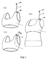
- Figs. 1 to 4 show a configuration for achieving buoyancy by using air that flows into a preserver body.
- Figs. 1 and 2 show an exemplary embodiment of the life preserver worn from the shoulders to the torso.
- Fig. 4 shows an exemplary embodiment of the life preserver worn on the torso.
- Figs. 7 to 10 show a configuration for achieving buoyancy by using a gas generated by a chemical reaction with water (or sea water) flowing into the preserver body.
- Figs. 7 to 9 show an exemplary embodiment of the life preserver worn from the shoulders to the torso.
- Fig. 10 shows an exemplary embodiment of the life preserver worn on the torso.
- the life preserver of the present invention shown in Figs . 1 and 2 is shaped as gear to be worn by a woman participating in sporting competitions or beach volleyball, but the life preserver of the present invention can be used by both men and women.
- Fig. 1(a) is a perspective view of the life preserver, and Fig. 1(b) shows a state in which the life preserver is actually worn.
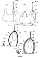
- Fig. 2(a) is a front view of the life preserver, and Figs. 2(b), (c), and (d) are vertical cross-sectional views of the life preserver as seen from the x-y direction.
- a hollow region 1b sealed from the outside is formed in the preserver body 1 that serves as the life preserver of the present invention, and a blow tube 2 that enables outside air to enter into the hollow region 1b is formed at the top of the preserver body 1.
- the blow tube 2 that sucks in the outside air is securely fixed by a fixing portion 2b to an air inlet 1a formed at the top of the preserver body 1, such that the blow tube 2 does not easily come loose.
- An air inlet 2a is disposed at the tip of the blow tube 2, to intake the outside air.
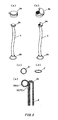
- the air inlet 2a includes a lid on the inlet through which the air is sucked in, as shown in Fig. 3 , and can therefore be in an open state or an artificially sealed state.
- the hollow region 1b is filled with a material serving as a resilient component 3, which deforms when pressure (a load) is added thereto from the outside and returns to an original unloaded form when the pressure (load) is removed.
- the resilient component 3 can be realized by an elastic member 3A, such as an elastic foam material, or a bias member 3B that deforms when pressure is added and returns to the original shape when the pressure is removed.
- the elastic member 3A can be realized by a plastic foam, as in the present embodiment, and the plastic foam can be continuous or noncontinuous.
- the plastic foam can be polystyrene foam, polyurethane foam (sponge), polyethylene foam, or polypropylene foam, for example.
- Each of these foams is elastic, deforms to have less volume in proportion to pressure added thereto, and returns to the original shape and volume due to elastic force when the deforming pressure is removed. With this deformation, air is sucked in or expelled to or from the inside of the foam plastic according to the amount of deformation. Therefore, the plastic foam is sealed in the hollow region 1b, and when the air is removed from within the hollow region 1b or pressure is added from outside the hollow region 1b, the plastic foam sealed therein is deformed to be smaller, thereby deforming the overall preserver body 1 to have less volume.
- a bias member 3B such as a flat spring or a compression spring, such as shown in Fig. 5(c) and (d) , is provided in the hollow region 1b.
- the bias member 3B can be realized by material other than a metal such as iron, and can be made of a rubber of plastic material having flexibility, for example.
- the elastic member 3A can also be realized by an elastic member other than plastic, such as a rubber material.
- the present invention uses the resilient characteristics of the elastic member 3A or the bias member 3B disposed within the sealed hollow region 1b to return these members to the original shapes when pressure is removed to achieve an unloaded state. Both of these members deform by bending or having reduced volume when a load is placed thereon adding pressure from the outside, and return to the original volume and shape when the pressure is removed. In accordance with the deformation of the elastic member 3A or the bias member 3B, air flows into the sealed hollow region 1b
- the present invention utilizes the resilient properties by increasing or decreasing pressure on the resilient component 3, in order to suck in or expel air to or from the hollow region 1b, and therefore the present invention truly utilizes natural laws.
- melamine foam which is a plastic foam
- the air may be sucked out from the hollow region 1b through the blow tube 2 using a vacuum pump apparatus, for example, or by pressing the entire preserver body 1 with a press machine, for example, to expel the air from the hollow region 1b.
- the opening of the air inlet 2a is closed in a sealed state or the opening is completely closed by being fused (laminated) by thermo-compression bonding, for example, thereby causing the overall preserver body 1 to be in a thin and flat state as shown in Fig. 2(c) .
- the inventor of the present invention actually pressed melamine foam with a thickness of 32 mm by adding a large amount of pressure, and was able to compress the melamine foam with a thickness of 32 mm to a thickness of merely 1 mm. If the preserver body 1 is formed by melamine foam compressed to a thickness of 1 mm in this way, this thickness is practically the same as that of sportswear used in competitions such as triathlons or a common swimsuit that has almost no buoyancy.
- Fig. 1(b) shows a state in which the life preserver is worn, and the thin and flat preserver body 1 fits on the body without being bulky.
- the blow tube 2 that transmits air into the hollow region 1b in the preserver body 1 is stored in a coiled state, as one example, within a pocket, not shown, which is bent as necessary and disposed on the back surface of the preserver body 1.
- the blow tube 2 can be stored by being inserted straight into the hollow region 1b of the preserver body 1.
- the blow tube 2 may have a circular cross section or an elliptical cross section, and can be stored in a thin and flat state if an elliptical cross section is chosen.
- the blow tube 2 With the elliptical shape shown in Fig. 3(d) , when the preserver body 1 has a large amount of pressure added thereto, the blow tube 2 becomes a flat board with no opening therein, and can therefore be stored without being bulky.
- the blow tube 2 can be formed to stand erect by its own elasticity (flexibility).
- the life preserver of the present embodiment can be worn while swimming and the life preserver has a thin and flat shape, and therefore there is no interference when swimming since the buoyancy of the overall preserver body 1 is not active. Furthermore, the sealing state of the air in the hollow region 1b can be adjusted such that the overall preserver body 1 has only a small amount of buoyancy, and in this state the upper portion of the body is made slightly buoyant, making swimming easier. Therefore, the life preserver can serve as a swimming aid while also providing security to someone who is beginning to learn to swim.
- the buoyancy of the preserver body 1 can also be set as desired by the user.
- the blow tube 2 stored in the preserver body 1 is removed and the air inlet 2a at the tip of the blow tube 2 can be opened (in the present embodiment, a lid is opened), as shown in Fig. 3(b) .
- the elastic member 3A in the loaded state which is a foaming material that is compressed and fills the hollow region 1b of the preserver body 1, changes to an unloaded state and the resilient (elastic) force thereof causes the elastic member 3A to expand and return to the original shape.
- Fig. 2(e) shows a configuration in which an air valve 2c is provided on the fixing portion 2b of the air inlet 2a.
- This configuration causes the air that is sucked in to the hollow region 1b to be held therein by the air valve 2c, and prevents the air sucked into the hollow region 1b from flowing back out through the blow tube 2.
- the air valve 2c can have the same configuration as valves used in conventional buoyancy bags, and when the user wants to remove the air from within the hollow region 1b, the air can be removed by pinching the fixing portion 2b with the fingers to open the air valve 2c. In an actual state where the life preserver of the present invention is worn and the entire preserver body 1 is floating, water does not enter into the hollow region 1b through the air inlet 2a even when the air inlet 2a is open.
- Fig. 2(e) describes a relationship between the water pressure F1 added to the preserver body 1 and the resilient force F2 of the bias member 3A.
- the water pressure F1 is applied horizontally to the surface of the preserver body 1 in proportion to the how deep in the water the preserver body 1 is.
- the water pressure F1 exerted on the surface of the preserver body 1 exerts a uniform pressure within the hollow region 1b of the preserver body 1, according to Pascal's principle, and therefore the water pressure F1 is added to each portion of the elastic member 3A disposed in the hollow region 1b
- the elastic member 3A deformed by the addition of pressure thereto exerts a resilient force F2 that attempts to return the elastic member 3A to the original shape.
- the preserver body 1 When the resilient force F2 is greater than the water pressure F1, the preserver body 1 naturally expands as air is sucked in through the air inlet 2a.
- the inventor of the present invention filled a preserver body 1 with an elastic member 3A made of melamine foam serving as a plastic foam. After an extremely large pressure was applied to compress the preserver body 1 into a thin and flat state, and the preserver body 1 was submerged in water to a depth of 50 cm.
- the preserver body 1 returned to the original form due to the resilient force of the melamine foam, air was sucked in through the air inlet 2a and the preserver body 1 expanded, thereby confirming through actual experimentation that the resilient force F2 of the melamine foam, which is the foam material, is greater than the water pressure F1 at a depth of 50 cm. Accordingly, when the hollow region 1b of the preserver body 1 is filled with a compressed elastic member 3A made of melamine foam serving as the plastic foam, even in a state where the head is submerged in the water as shown in Fig.
- the configuration for the air inlet 2a at the tip of the blow tube 2 may differ from the configuration shown in Fig. 3(a) and (b) , and any configuration can be used for the air inlet 2a as long as the inlet can be opened.
- a notch can be formed on a side of the blow tube 2 and the air inlet 2a can be opened from the notch by inserting a finger into a ring portion formed thereabove and pulling.
- the air inlet 2a is preferably configured in a manner to be opened with one hand.
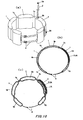
- Fig. 4 shows a second exemplary embodiment of the life preserver according to the present invention.
- a plurality of preserver bodies 1 are provided and a hollow region 1b is formed in each preserver body 1, and the hollow regions 1b are in communication with each other via communicating holes 1c.
- the hollow region 1b in each preserver body 1 is filled with a resilient member 3, and air can move freely among the hollow regions 1b via the communicating holes 1c.
- Fig. 4(b) shows a state in which the hollow regions 1b are filled with compressed elastic members 3(a).
- FIG. 4(c) shows a state in which the air inlet 2a is opened and air is sucked in through the air inlet 2a by the resilient force of the elastic members 3(a), thereby returning the preserver body 1 to the original shape.
- a sealed bag experiences a uniform pressure at all points, and therefore each preserver body 1 is compressed with the same pressure and expands with the same pressure when air is sucked in through the air inlet 2a.
- the life preserver can be wrapped around the torso, allowing for swimming and playing in the water as in the state shown by Fig. 6(c) .
- the configuration of the present embodiment includes a fastener band 4 that wraps the life preserver around the torso, and the life preserver is fixed securely in place around the torso by a buckle.
- the fastener band 4 is preferably configured to enable secure fastening, and since there is a concern that Velcro (Registered Trademark: Magic Tape) can slip, the fastener band 4 preferably includes a fastener that can be locked.
- the air inlet 2a may have any configuration that enables the inlet to be opened, and it is preferable that the opening operation be performable with one hand.
- the length and thickness of the blow tube 2 may be set as desired.
- the length of the blow tube 2 can be set up to a length that us as far as a hand can be extended, in order to enable even a drowning person to reliably operate the blow tube 2 above the water surface.
- the elastic member 3A that is compressed and fills the preserver body 1 may include a plurality of uneven portions 3a, as shown in Fig. 5(a) and (b) . With this configuration, an elastic member 3A with a strong resilient force can be realized, and therefore a lesser amount of the elastic member 3A can be used and the time needed for the elastic member 3A to return to the original shape can be reduced.
- the air sucked into the preserver body 1 and the resilient member 3 (particularly the elastic member 3A) disposed in the preserver body 1 have extremely high specific heat, and therefore achieve a thermal insulation effect.
- body temperature can be trapped near the body and prevented from escaping, and keeping this body heat trapped can increase the length of time that a person can wait to be rescued.
- the life preserver of the present invention is not bulky, and therefore can also be worn as normal clothing for warmth.
- the attached air compression pump can only be used once, but with the life preserver of the present invention, by expelling the air from the preserver body 1 by applying pressure from the outside or by sucking the air out of the preserver body 1 from the outside and then closing the air inlet 2a while there is no air in the preserver body 1, the preserver body 1 can again achieve a sealed state and can be reused as many times as needed.
- Figs. 7 to 9 show a third exemplary embodiment of the life preserver of the present embodiment.
- the previous embodiments are designed such that air is sucked in from above the water surface and used to achieve buoyancy. In the present embodiment, however, buoyancy can be obtained even if sea water from the ocean or water from a pool, river, or lake is sucked in.
- a foaming agent is used that generates gas by having a chemical reaction with water.
- the foaming agent can be an additive that is added to baths, for example.
- the inventor of the present invention actually performed the test shown in Fig.
- the present embodiment utilizes the resilient force (i.e. the force to deform when pressure is added and to return to the original shape when the pressure is removed) of the bias member 3B or the elastic member 3A, which serve as the resilient member, and the configuration of this embodiment is described in detail below based on the drawings.
- a water inlet 2d is disposed in an upper portion of the preserver body 1 and the blow tube 2, which transmits water sucked in through the water inlet 2d downward into the hollow region 1b of the preserver body 1, is disposed within the hollow region 1b.
- a foaming portion 1A filled with the foaming agent and the elastic member 3A are disposed together below the exhaust end of the blow tube 2.
- the air within the hollow region 1b of the preserver body 1 is sucked out by a vacuum pump or the like to form a vacuum state or the entire preserver body 1 is pressed with a large amount of pressure to remove enough air from the preserver body 1 that the preserver body 1 becomes flat and thin, an the water inlet 2d is then closed to keep the preserver body 1 in a sealed state.
- a pressure (load) is constantly applied to compress the elastic member 3A disposed at the bottom of the hollow region 1b.
- the resilient force of the elastic member 3A for returning to the original shape is held in check. As shown in Fig.
- This sucked-in water flows to over the foaming portion 1A at the bottom of the hollow region 1b, thereby causing a chemical reaction between the foaming agent of the foaming unit 1A and the water to begin generating gas.
- the generated gas carbon dioxide gas
- the generated gas gradually fills the hollow region 1b until, as shown in Fig. 7(e) , the generated gas (carbon dioxide gas) creates buoyancy in the preserver body 1. Therefore, when the life preserver of the present embodiment is worn, this generated buoyancy is used to enable floating on the water surface.
- the amount of foaming agent disposed in the hollow region 1b should sufficient to completely fill the hollow region 1b with the gas generated as a result of the chemical reaction with the water.
- the water inlet 2d can be closed again to prevent the generated gas from leaking to the outside.
- the present embodiment includes a valve that opens only in the direction in which the water is sucked-in, as shown in Fig. 2(e) , within the blow tube 2 passing to the water inlet 2d, and therefore the generated gas in the preserver body 1 is prevented from leaking to the outside.
- the foaming agent may be injected within the elastic member 3A in advance such that, when the elastic member 3A expands, the gas is generated by the chemical reaction with the foaming agent as the water is sucked in.
- Fig. 8 shows a configuration through which the preserver body 1 achieves buoyancy due to the expansion of the hollow region 1b regardless of whether water or air is sucked into the hollow region 1b of the preserver body 1.
- the air inlet 2a is opened while protruding above the water surface in the state shown in Fig. 8(c) , in the same manner as in the embodiment shown in Figs. 1 and 2 .
- the resilient force of the elastic member 3A that is compressed and fills the entire hollow region 1b acts to suck in air through the opened air inlet 2a into the hollow region 1b, causing the entire preserver body 1 to expand as shown in Fig. 8(e) .
- the preserver body 1 then achieves buoyancy and can float on the water surface.
- the air inlet 2a can also be used as the water inlet 2d, and when opened in a submerged state as the water inlet 2d, the resilient force of the elastic member 3A within the hollow region 1b acts to cause expansion, while at the same time the unloaded state is achieved in the hollow region 1b.
- the resilient force of the elastic member 3A in the hollow region 1b is always active, and therefore the hollow region 1b is prevented from collapsing by the resilient force. Therefore, even after the gas-generating reaction of the foaming agent ends, water does not flow from the water inlet 2d, and so there is no need to include the valve that is used in the previous embodiments. Even if someone is drowning and lacks the calmness to open the air inlet 2a above the water surface as shown in Fig. 6(b) , the water inlet 2d can be opened while under water such that water flows into the hollow region 1b and reacts with foaming agent to generate gas. Therefore, even when the water inlet 2d is opened in water, the same state as shown in Fig. 8(e) is achieved, where the entire preserver body 1 achieves buoyancy and can float above the water surface.
- Fig. 9 shows a configuration in which the water inlet 2d is disposed in a lower region of the preserver body 1.
- a person does not remain calm when drowning, and when a person is submerged as shown in Fig. 11 (b) , it can be difficult to operate the air inlet 2a or the water inlet 2d if these inlets are positioned at an upper portion of the preserver body 1 as in the previous embodiments. Therefore, when the water inlet 2d is at a lower portion of the preserver body 1 as in the present embodiment, the water inlet 2d can be operated (opened) in the water to expand the preserver body 1 and enable floating above the water surface.
- the compressed elastic member 3A fills the bottom of the hollow region 1b in the thin and flat state shown in Fig. 9(c) .
- the foaming portion 1A including the foaming agent is disposed together with the elastic member 3A.
- the elastic member 3A expands due to the resilient force, thereby creating negative pressure within the hollow region 1b that causes water to be sucked in through the water inlet 2d.
- the sucked-in water permeates the foaming agent and causes a chemical reaction that generates gas (carbon dioxide gas).
- the generated gas (carbon dioxide gas) fills and expands the hollow region 1b, and therefore the entire preserver body 1 expands to achieve buoyancy and float above the water surface, in the same manner as in the previous embodiments.
- the opening of the water inlet 2d is provided with a filter 5 and the water passes through the filter 5 to permeate the foaming agent. This filter 5 prevents the foaming agent from leaking out from the opening of the water inlet 2d.
- Fig. 10 shows a fourth exemplary embodiment of the present invention, in which the elastic member 3A is disposed together with the foaming portion 1A including the foaming agent within one of the preserver bodies 1 in the life preserver having the configuration shown in Fig. 4 .
- the water inlet 2d disposed on this preserver body 1 is opened to create a chemical reaction between the water sucked in through the water inlet 2d and the foaming agent, in the same manner as in the previous embodiment, and the gas (carbon dioxide gas) generated by the chemical reaction fills and expands the hollow region 1b.
- the generated gas causes each preserver body 1 in communication via the communicating holes 1c to expand, and therefore each preserver body 1 achieves buoyancy in the same manner as in the previous embodiment.
- the hollow region 1b is not filled by the elastic member 3A, but each embodiment may instead completely fill the hollow region 1b with the elastic member 3A, or may fill the hollow region 1b with a suitable amount of the elastic member 3A.
- a suitable amount of a chemical component such as aluminum powder or calcium lime
- the preserver body 1, blow tube 2, air inlet 2a, and water inlet 2d in each embodiment can be formed by a resin such as vinyl chloride.
- the life preserver of the present invention provides thermal insulation, and therefore can be worn as clothing for warmth, in addition to having the life-saving benefits.
- the life preserver can be formed as a vest, whit a zipper that opens and closes the front, for example.
- the air inlet 2a and the water inlet 2d may be opened by forcibly tearing the tips thereof.
- the foaming agent that generates the gas (carbon dioxide gas) as a result of chemically reacting with water or sea water may include sodium hydrogen carbonate and tartaric acid as a primary component, or citric acid and baking soda can be separated and then mixed with the sucked-in water to cause a chemical reaction and generate gas.
- the air inlet 2a may be provided to suck air directly into the hollow region 1b and the water inlet 2d may be provided to suck water or sea water directly into the hollow region 1b.
- the inlets can be implemented at suitable positions such that the sucked-in water or sea water flows over the foaming agent of the foaming portion 1A, in order for the resilient force of the resilient component 3 to be active.
- Fig. 12 shows an example in which the air inlet 2a sucks in air without being immersed in water. Since a drowning person is not calm, is can be difficult for this person to reliably raise the air inlet 2a above the water surface. Therefore, this configuration guarantees that the air inlet 2a will be above the water surface even if the air inlet 2a is opened under water, and therefore an elastic member 3A that does not suck in water is disposed with a suitable size around the blow tube 2, as shown in the drawings.
- the elastic member 3A is stored in a compressed state within a cylinder 6, and when the cylinder 6 is lifted up in an emergency to release the elastic member 3A from within the cylinder 6, such that the elastic member 3 returns to the its original spherical size due to the resilient force.
- the elastic member 3A exhibits buoyancy and floats above the water surface, and therefore the air inlet 2a is kept above the water surface and is able to suck in air.
- the air inlet 2a may be configured to open at the same time that the operation is performed to pull the cylinder 6 upward.
- Figs. 14 and 15 show a fifth embodiment of the present invention
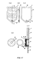
- Figs. 16 and 17 show a sixth embodiment of the present invention
- Fig. 18 shows a seventh embodiment of the present invention.
- the preserver body 1 expands according to an operation from outside the preserver body 1 to achieve buoyancy, in the same manner as in the previous embodiments.
- the hollow region 1b is formed within the preserver body 1 in a sealed state, in the same manner as in the previous embodiments.
- the foaming portion 1A including the foaming agent that generates the gas by reacting with a liquid is disposed at the bottom of the preserver body 1, as shown in the drawings.
- the foaming portion 1A may be provided with the foaming agent exposed, or the foaming agent may be wrapped in a cloth, gauze, or paper that is dissolved by the liquid, for example.
- the foaming agent may be wrapped in a water-soluble material 11, which is described further below.
- a pocket 1B with a recessed shape is formed at the center of the bottom of the preserver body 1, as shown in the drawings.
- the pocket 1B may be shaped as a recessed portion at the bottom center of the preserver body 1, or may be formed as a protruding tongue that protrudes into the preserver body 1.
- the liquid bag 7 disposed in the preserver body 1, using Fig. 14(c) and (d) .
- the liquid bag 7 is formed of polyethylene or the like and, as shown in Fig. 14(c) , seals in a reactive liquid 9 that reacts with the foaming agent to generate gas.
- a bonded portion 7d that is bonded by thermo-compression is formed on the edges of the liquid bag 7. In this state, the reactive liquid 9 is sealed within the liquid bag 7 and does not leak out.
- wedge-shaped notches 7a are formed at both edges of the bonded portion 7d of the liquid bag 7, as shown in the drawings, an opening 7b is formed as a triangular opening, and a pulling hole 7c is formed as a circular opening.
- the liquid bag 7 is fixed within the preserver body 1, the pulling hole 7c formed at the bottom of the liquid bag 7 protrudes within the pocket 1B, and the preserver body 1 is in a sealed state.
- the method for fixing the liquid bag 7 within the preserver body 1 includes forming an affixing portion 7e over the entire back surface of the portion above the notches 7a, as shown in Fig.
- the liquid bag 7 is torn at the wedge-shaped notches 7a, so that the reactive liquid 9 within the liquid bag 7 is released.
- the released reactive liquid 9 flows downward due to gravity and mixes with the foaming agent of the foaming portion 1A to cause a chemical reaction and begin generating gas.
- the generated gas fills the hollow region 1b of the preserver body 1, causing the preserver body 1 to obtain buoyancy in the water due to the generated gas.
- the inventor of the present invention performed an experiment with a bag made of polyethylene with a thickness of 0.08 mm, and a bag made of resin is considerably strong in the pulling direction and does not tear even when a large pulling force is applied. In contrast, the strength of this bag in the tearing direction is fairly low, and therefore the bag can be torn in the tearing direction with a small pulling force. Therefore, the liquid bag 7 can be easily torn if the pulling hole 7c is pulled downward in the state shown in Fig. 14(a) . As a result, the reactive liquid 9 sealed in the liquid bag 7 is immediately released and causes a chemical reaction with the foaming agent, thereby achieving buoyancy for the preserver body 1 a few seconds later due to the generated gas.
- the pulling hole 7c being operated is hidden within the pocket 1B, and therefore the preserver body 1 does not expand unless a finger is intentionally inserted within the pocket 1B and the pulling hole 7c is pulled.
- the generated gas rises and collects at the top even if the pocket 1B is not sealed, and therefore buoyancy can be achieved.
- the pocket 1B is preferably completely sealed.
- Fig. 15 shows a configuration of an exemplary embodiment that can be operated from the top edge of the preserver body 1.
- the foaming portion 1A is formed at the bottom of the preserver body 1
- the pocket 1B which is the same as in the previous embodiment, is formed at the top edge of the preserver body 1.
- the reactive liquid 9 is sealed in the liquid bag 7 and the edges thereof are bonded to form the bonded portion 7d.
- Wedge-shaped notches 7a are formed at both edges in a lower portion of the bonded portion 7d of the liquid bag 7, a opening 7b is formed as a triangular opening in the upper portion of the liquid bag 7, and a pulling hole 7c is formed as a circular opening.
- an affixing portion 7e is formed over the entire back surface of the portion below the notches 7a, and the liquid bag 7 is affixed by the affixing portion to the inner surface of the preserver body 1, as shown in Fig. 15(a) .
- the pointer finger is inserted in the pulling hole and pulled upward, the force of the finger pulling up on the pulling hole 7c is applied as shown by the arrows in Fig.
- the liquid bag 7 is torn at the wedge-shaped notches 7a, so that the reactive liquid 9 is released to cause a chemical reaction with the foaming agent and begin generating gas, in the same manner as the previous embodiment, thereby causing the preserver body 1 to obtain buoyancy.
- the pulling force from outside the preserver body 1 is added to a prescribed portion of the liquid bag 7 within the preserver body 1 to rip the liquid bag 7 at the prescribed portion.
- the portion to be ripped may be a perforated line or the like formed on the liquid bag 7.
- Figs. 16 and 17 show configurations of exemplary embodiments in which the operation for tearing the liquid bag 7 is achieved by a pressing operation from outside the preserver body 1.
- interposed boards 7f formed as opposing arcs with suitable thickness at the bottom region within the liquid bag 7 are affixed to the inner surface of the liquid bag 7 (or to the outer surface of the liquid bag 7). In this state, the surface of the liquid bag 7 between the interposed boards 7f is held in a stretched state. The reactive liquid 9 sealed within the liquid bag 7 can flow freely between the interposed boards 7f.
- an operating portion 8 that is operated outside the sealed liquid bag 7 is provided at a position that overlaps the interposed boards 7f, and the operating portion 8 forms a chassis 8c that is open at both sides and includes a circular operation hole 8e in the center thereof.
- a resilient portion 8d having elasticity and a needle portion 8a including one or more needles having sharpened points formed on a disc above the resilient portion 8d are disposed in the chassis 8c.
- the liquid bag 7 including the operating portion 8 is affixed within the preserver body 1, as shown in Fig. 18(c) .
- the actual liquid bag 7 tearing operation is performed as shown in Fig. 18(e).
- the position of the operation hole 8e in the center of the chassis 8c is found by the pointer finger from outside the preserver body 1, and when this position is pressed hard by the pointer finger, the resulting force causes the surface contact the preserver body 1 to be depressed, thereby pressing the needle portion 8a inward.
- the needles formed on the needle portion 8a puncture the portion of the preserver body 1 that is contacted, creating holes.
- the needle portion 8a returns to the original position due to the elastic force of the resilient portion 8d, so that the reactive liquid 9 is released from the preserver body 1 through the opened holes and chemically reacts with the foaming agent of the foaming portion 1A to begin generating gas.
- the preserver body 1 is filled with the generated gas and the preserver body 1 achieves buoyancy, in the same manner as in the previous embodiments.
- Figs 17A to 17E show a configuration in which the needle portion 8a of the operating portion 8 in Fig. 16 is replaced by a cutter portion 8b in which a blade with a ring of protrusions having sharpened tips are formed on a disc.
- the cutter portion 8b is pressed inward, which causes the liquid bag 7 to be torn by the ring of protruding blades.
- a circular hole can be formed in the liquid bag 7, and the reactive liquid 9 released from this hole chemically reacts with the foaming agent of the foaming portion 1A to begin generating gas, thereby achieving buoyancy for the preserver body 1 in the same manner.
- a pressing force is added perpendicular to a stretched surface of the liquid bag 7 by needles or blades formed with sharpened tips.
- the force in the pressing direction creates a wedging effect that expands the openings of the surface. Therefore, even if the blades or needles are not moved laterally after penetrating the surface of the liquid bag 7, large holes can be opened in the liquid bag 7 simply by adding force in a perpendicular direction for pressing the bag surface. With this operation, unless a finger is inserted into the operation hole 8e portion and intentionally presses down, the liquid bag 7 is not torn.
- Fig. 18 shows an exemplary embodiment in which a latch structure is disposed in the operating portion 8, and in which operating the bias member 3B, which is set in the latched state in advance, from outside the preserver body 1 to release the bias member 3B from the latched state, the resilient force returning the bias member 3B to the original shape serves to tear the liquid bag 7.
- the bias member 3B formed by a flat spring is disposed in the chassis 8c while bent with a strong force, as shown in the drawings, and a operation hook 8f bent to the outside is formed at the top of the bias member 3B.
- the operation hook 8f protrudes from the operation hole 8e, and the bent end thereof is set to the latched state as shown in the drawings.
- the needle portion 8a formed on the bias member 3B does not contact the liquid bag 7.
- the operation hook 8f is released from the latched state and the bias member 3B changes from the loaded state to the unloaded state. Therefore, the operation hook 8f is pulled into the operation hole 8e by the resilient force of the bias member 3B, and at the same time the needle portion 8a formed on the bias member 3B pierces and tears the liquid bag 7. The reactive liquid 9 in the torn liquid bag 7 is gradually released.
- the reactive liquid 9 gradually flows from through the opened sides of the chassis 8c downward into the preserver body 1, and chemically reacts with the foaming agent of the foaming portion 1B to generate gas.
- the liquid bag 7 is preferably torn open with as simple an operation as possible, and the configuration of the present embodiment simplifies this operation.
- the present embodiment shows an exemplary latch structure realized by a flat spring, but the properties of a bias member other than a flat spring, i.e. the ability to deform when pressure is added and return to an original shape when the pressure is removed, can be used to create any structure that can be set in a latched state in advance and released from the latched state during an emergency or when necessary to tear the liquid bag 7.
- the cutter portion 8b may be used instead of the needle portion 8a to tear the liquid bag 7.
- an enclosure not shown, with a suitable size may be formed around the operation hook 8f.
- Fig. 19 shows a configuration of an exemplary embodiment a liquid bag 7.
- the reactive liquid 9 sealed in the liquid bag 7 occupies 80% to 100% of the liquid bag 7 and the liquid bag 7 is stepped on as shown in Fig. 19(a) .
- the liquid bag 7 is filled with the reactive liquid 9 up to 40% to 60% such that the liquid bag 7 remains thin and flat.
- the reactive liquid 9 within the liquid bag 7 flows around the foot and does not add pressure to the inside of the liquid bag 7, and therefore the liquid bag 7 is not ripped.
- the bonded portion 7d bonding the inner surfaces of the liquid bag 7 to each other is formed at suitable locations, as shown in Fig. 19(c) .
- the liquid bag 7 of the present invention may be formed by a suitable resin other than polyethylene, and can be formed of any material that is strong with respect to pulling and weak with respect to tearing.
- the elastic member 3A may be disposed in the preserver body 1 in a compressed state and expand according to the gas generated in the preserver body 1, in the same manner as in the previous embodiments.
- the elastic member 3A may be provided in an uncompressed state within the preserver body 1.
- Each embodiment may include a configuration in which the reactive liquid 9 chemically reacts with the foaming agent of the foaming portion 1A to generate gas.
- the reactive liquid 9 may be sterile water and the foaming agent in the previous embodiments that generates gas by chemically reacting with water or sea water may be manganese dioxide, which is a catalyst for the reactive liquid with hydrogen peroxide, such that the generated gas is oxygen. Therefore, when a person is drowning and lacks oxygen, the person can breathe the gas generated in the preserver body 1.
- a strap or the like may be connected to the liquid bag 7 in advance, such that the liquid bag 7 can be torn by pulling the strap.
- a needle or blade that tears the liquid bag 7 when the strap is pulled may be provided, such that the needle or blade is brought into contact with the liquid bag 7 to tear the liquid bag 7.
- the pocket 1B may be disposed on a side of the preserver body 1, and the liquid bag 7 oriented sideways in the liquid bag 7 can be torn by being pulled sideways.
- a sufficient reaction occurs between the foaming agent of the foaming portion 1A within the hollow region 1b of the preserver body 1 and water sucked into the hollow region 1b of the preserver body 1, in order to sufficiently expand the overall preserver body 1.
- the resilient force of the resilient member 3 causes water to be sucked into the hollow region 1b of the preserver body 1, and the sucked-in water quickly reacts with the foaming agent of the foaming portion 1A to begin generating gas.
- the negative pressure state of the hollow region 1b of the preserver body 1 is eliminated not only by the sucked-in water, but also by the generated gas. Therefore, it is necessary to suck in a large amount of water all at once into the hollow region 1b of the preserver body 1. In this case, it is difficult to set the relationship with respect to the resilient deformation speed of the resilient member 3 (elastic member 3A or bias member 3B).
- the embodiments shown in Figs. 20 and 21 include an amount of foaming agent sufficient to expand the entire preserver body 1 within the hollow region 1b of the preserver body 1. After a suitable amount of water is sucked into the hollow region 1b of the preserver body 1, the sucked-in water begins reacting with the foaming agent. The following provides a detailed description of the configuration for each embodiment.
- the hollow region 1b of the preserver body 1 is filled with the elastic member 3A, which may be a sponge or melamine foam, for example, the entire preserver body 1 is pressed by a press machine or the like to sufficiently compress the elastic member 3A and remove the air from the hollow region 1b of the preserver body 1, and then the water inlet 2d is closed to be in a sealed state. In this state, even if the pressure of the pressing is removed from the entire preserver body 1, the preserver body 1 remains in a compressed flat and thin state without containing air.
- the elastic member 3A which may be a sponge or melamine foam
- An amount of foaming agent for sufficiently expanding the entire preserver body 1 is disposed in advance at the bottom of the preserver body 1, and the foaming portion 1A is formed by covering the entire top of the foaming agent with the water-soluble material 11 that dissolves in water.
- the force of the pulling causes the water inlet 2d to open, and at the same time the resilient force of the elastic member 3A in the preserver body 1 acts to return the elastic member 3A to the original shape.
- an amount of foaming agent sufficient to expand the entire preserver body 1 is disposed in advance in the hollow region 1b of the preserver body 1, and when a suitable amount of water is then sucked in and reacts with the foaming agent, the entire preserver body 1 is sufficiently expanded to achieve sufficient buoyancy.
- the setting for how much time the reaction between the foaming agent and the sucked-in water is actually delayed by can be determined by the thickness and the material of the water-soluble material 11.
- the material for forming the water-soluble material 11 that dissolves in water can be a material that reacts to water by dissolving, such as a vegetable polysaccharide water-soluble film made of starch from potatoes or sweet potatoes, such as oblaat, a water-soluble film having polyvinyl alcohol (PVA) as a primary component, or a water-soluble plastic film made of poval resin.
- a suitable gap is left between the foaming agent 1A and the elastic member 3A filling the hollow region 1b of the preserver body 1, such that a sufficient amount of water can be accumulated therebetween.
- Fig. 20(b) shows an exemplary embodiment of actual implementation of the foaming portion 1A.
- the foaming agent fills the water-soluble material 11, which is a water-soluble film, like a sausage, and the foaming portion 1A containing the foaming agent is provided as-is in the hollow region 1b of the preserver body 1, thereby realizing the present invention easily. With this configuration, manufacturing is extremely simple, safe, and reliable.
- the preserver body 1 may be made of a material that does not let moisture pass through, and/or a drying agent may be disposed within the preserver body 1. Fig.
- a reservoir 10 is disposed at the bottom of the hollow region 1b of the preserver body 1, as shown in the drawings, and the foaming portion 1A shown in Fig. 20(b) is disposed in the reservoir 10.
- the generated gas passes through the vent hole 10a to fill the hollow region 1b of the preserver body 1, so that the entire preserver body 1 can be expanded by the generated gas.
- the sucked-in water is reliably accumulated in the reservoir 10 and reliably reacts with the foaming agent, and therefore the present invention can be safely and reliably implemented with standardized quality.
- Fig. 21 shows an exemplary embodiment that achieves the same effect as the embodiment shown in Fig. 20 .
- the reservoir 10 is provided to store a suitable amount of water sucked into the hollow region 1b of the preserver body 1.
- the stored water begins flowing into the hollow region 1b of the preserver body 1.
- This water flows over the foaming agent of the foaming portion 1A disposed at the bottom of the hollow region 1b of the preserver body 1, and creates a reaction.
- the elastic member 3A in the preserver body 1 is compressed, so that the overall preserver body 1 has a thin flat shape.
- the water inlet 2d is closed to be in the sealed state, and so water is not sucked into the hollow region 1b of the preserver body 1.
- the water inlet 2d is opened, and at the same time the resilient force causes the elastic member 3A to return to the original shape, as shown in Fig. 21 (c) and (d) , during which time water begins to be sucked into the water inlet 2d.
- the sucked-in water is gradually accumulated in the reservoir container 10A after flowing through the blow tube 2, and at the same time the air in the reservoir container 10A is expelled from the vent hole 10a.
- the water stored in the reservoir container 10A When the water stored in the reservoir container 10A reaches a height greater than or equal to the peak h of an inverted U-shaped tube 10b disposed in the reservoir container 10A, the water stored in the reservoir container 10A flows into the inverted U-shaped tube 10b, according to the siphon principle, and begins to flow over the foaming agent of the foaming portion 1A in the hollow region 1b of the preserver body 1. At this time, the water sucked into the preserver body 1 begins reacting with the foaming agent to generate gas for the first time.
- the preserver body 1 While the gas is being generated, even though the hollow region 1b of the preserver body 1 has negative pressure due to the generated gas, the water in the reservoir container 10A continues to flow without being affected at all by the change of the negative pressure state, and continues flowing up to the height of the inlet of the inverted U-shaped tube 10b. Therefore, by including the foaming agent that sufficiently expands the entire preserver body 1 disposed in advance in the hollow region 1b of the preserver body 1 and the reservoir container 10A that sores a suitable amount of water for reacting with this foaming agent, the preserver body 1 can be sufficiently expanded in an emergency to reliably achieve buoyancy.
- a person who is drowning can be saved within 10 to 20 seconds.
- the amount of water that is suitable for storage in the reservoir container 10A may be set as is appropriate for the size of the container, and the stored water amount can be set to determine approximately how many seconds the reaction with the foaming agent is delayed by.
- it is difficult to set the preserver body 1 to reliably achieve sufficient expansion but with the embodiments of Figs. 20 and 21 , the entire preserver body 1 can be reliably expanded, regardless of how many times this expansion is implemented.
- the reservoir container 10A can be formed of polyethylene or vinyl chloride having a suitable thickness, for example.
- the foaming unit 1A containing the foaming agent wrapped in the water-soluble material 11 shown in Fig. 20(b) can be disposed at the bottom of the hollow region 1b of the preserver body 1 shown in Fig. 21 .
- the water-soluble material 11 can be set to dissolve in a few seconds.
- a check valve may be disposed in the water inlet 2d to prevent reverse flow, in order to prevent the gas generated in the preserver body 1 from leaking to the outside.
- disposing the water inlet 2d at the torso region instead of the shoulder region can more reliably ensure that water or sea water is sucked in.
- the bottom of the container reservoir 10A may be formed by the water-soluble material 11 that dissolves in water, as shown in Fig. 20(d) , or the entire reservoir container may be formed by the water-soluble material 11.
- the water-soluble material 11 dissolves and the accumulated water naturally falls.
- a configuration can be used in which the suitable amount of water accumulated in the reservoir container 10A can automatically drop due to its own weight. Any means can be used as long as, when the suitable amount of water is sucked into the preserver body 1, the water automatically reacts with the foaming agent after a suitable time has passed.
- the life preserver of the present embodiment can be worn on the body in a thin and flat state during work or swimming.
- the preserver body 1 is operated from the outside to expand the preserver body 1 and achieve buoyancy, and therefore each embodiment has a special technical feature.
- 1 preserver body, 1A: foaming section (gas generating section), 1B: pocket, 1a: air inlet, 1b: hollow region, 1c: through-hole, 2: blow tube, 2a: air inlet, 2b: fixing portion, 2c: air valve, 2d: water inlet, 3: resilient component, 3A: elastic member, 3B: bias member, 3a: uneven portion, 4: fastener band, 5: filter, 6: cylinder, 7: liquid bag, 7a: notch, 7b: opening, 7c: pulling hole, 7d: bonded portion, 7e: affixing portion, 7f: interposed board, 8: operating portion, 8a: needle portion, 8b: cutter portion, 8c: chassis, 8d: resilient portion, 8e: operating hole, 8f: operation hook, 9: reactive liquid, 10: reservoir, 10A: reservoir container, 10a: vent hole, 10b: U-shaped hole, 11: water-soluble material
Landscapes
- Engineering & Computer Science (AREA)
- Mechanical Engineering (AREA)
- Ocean & Marine Engineering (AREA)
- Professional, Industrial, Or Sporting Protective Garments (AREA)
Applications Claiming Priority (4)
| Application Number | Priority Date | Filing Date | Title |
|---|---|---|---|
| JP2009195584 | 2009-08-26 | ||
| JP2009242644 | 2009-10-21 | ||
| JP2010044293 | 2010-03-01 | ||
| PCT/JP2010/064657 WO2011024981A1 (ja) | 2009-08-26 | 2010-08-23 | 救命浮き袋 |
Publications (2)
| Publication Number | Publication Date |
|---|---|
| EP2471706A1 true EP2471706A1 (de) | 2012-07-04 |
| EP2471706A4 EP2471706A4 (de) | 2017-07-26 |
Family
ID=43628076
Family Applications (1)
| Application Number | Title | Priority Date | Filing Date |
|---|---|---|---|
| EP10812030.4A Withdrawn EP2471706A4 (de) | 2009-08-26 | 2010-08-23 | Rettungsring |
Country Status (4)
| Country | Link |
|---|---|
| US (2) | US8801484B2 (de) |
| EP (1) | EP2471706A4 (de) |
| JP (2) | JP5563404B2 (de) |
| WO (1) | WO2011024981A1 (de) |
Cited By (1)
| Publication number | Priority date | Publication date | Assignee | Title |
|---|---|---|---|---|
| WO2014191093A3 (de) * | 2013-05-25 | 2015-01-29 | Christopher Fuhrhop | Schutz- und rettungsvorrichtung |
Families Citing this family (10)
| Publication number | Priority date | Publication date | Assignee | Title |
|---|---|---|---|---|
| US20150360759A1 (en) * | 2010-09-16 | 2015-12-17 | Zactill Intellectual Property Pty Ltd | Safety Device and Inflating Apparatus Therefor |
| WO2013126705A1 (en) * | 2012-02-22 | 2013-08-29 | Malcolm Adam J | Personal flotation device having selectively inflatable bladders |
| PT3157807T (pt) * | 2014-06-19 | 2021-06-07 | Agapiades Athanasios | Dispositivo pessoal de flutuação a usar no corpo |
| JP5826344B1 (ja) * | 2014-08-28 | 2015-12-02 | 正治 市原 | 浮力体及びこれを用いた救命胴衣 |
| CN108936860B (zh) * | 2016-08-29 | 2020-05-19 | 戴碧堂 | 一种背心式安全充气救生服 |
| JP6872898B2 (ja) * | 2016-12-26 | 2021-05-19 | 正治 市原 | 救命胴衣 |
| GB2588110B (en) * | 2019-10-07 | 2023-09-13 | Survitec Group Ltd | Slide fastener |
| CN111746761B (zh) * | 2020-06-23 | 2022-03-15 | 万舟救生装备(东台)有限公司 | 一种安全性高的多功能激流救援救生衣及使用方法 |
| CN112075377B (zh) * | 2020-08-20 | 2022-04-22 | 中国科学院水生生物研究所 | 一种可用于江豚的可穿戴载具 |
| KR102816519B1 (ko) * | 2024-07-17 | 2025-06-05 | 주식회사 에스엘상사 | 발열기능을 구비한 잠수복 |
Family Cites Families (19)
| Publication number | Priority date | Publication date | Assignee | Title |
|---|---|---|---|---|
| US205617A (en) * | 1878-07-02 | Improvement in life-preserving satchels | ||
| US3584A (en) * | 1844-05-10 | Lifepreservers which are also | ||
| US1600263A (en) * | 1925-03-09 | 1926-09-21 | John H Williams | Life preserver |
| JPS4513562Y1 (de) | 1965-07-21 | 1970-06-10 | ||
| US3510895A (en) * | 1968-05-10 | 1970-05-12 | Richard H Wynne | Life saver for swimmers |
| US3820956A (en) * | 1972-06-01 | 1974-06-28 | Gen Electric | Kipp type gas generator with movable liquid reactant exit port |
| JPS6282900U (de) * | 1985-11-15 | 1987-05-27 | ||
| JPS6385493U (de) * | 1986-11-21 | 1988-06-03 | ||
| JPS6393299U (de) * | 1986-12-08 | 1988-06-16 | ||
| JPH0512244Y2 (de) * | 1987-10-31 | 1993-03-29 | ||
| JPH038094U (de) | 1989-06-12 | 1991-01-25 | ||
| JPH0734854Y2 (ja) * | 1990-04-19 | 1995-08-09 | 株式会社太洋商会 | 膨らみ可能な密封袋 |
| JPH07223587A (ja) | 1994-02-10 | 1995-08-22 | Hiroyuki Hori | 自動膨張式救命胴衣 |
| JPH08104291A (ja) * | 1994-09-30 | 1996-04-23 | Kazuo Okunishi | 水中で膨張し形成される浮袋 |
| JPH10329789A (ja) * | 1997-05-30 | 1998-12-15 | Tokyo Seat Kk | 浮力付与具 |
| JP2000318683A (ja) * | 1999-05-07 | 2000-11-21 | Nippon Tansan Gas Co Ltd | ライフジャケット |
| BR0104789B1 (pt) * | 2001-09-25 | 2011-01-25 | disposição construtiva em roupa salva-vidas. | |
| JP3542125B2 (ja) * | 2002-01-07 | 2004-07-14 | 株式会社ワイズギア | ガス膨張式ライフジャケット |
| GB2387356A (en) * | 2002-04-13 | 2003-10-15 | Nicola Jane Haigh | Self inflating buoyancy device |
-
2010
- 2010-08-20 JP JP2010185159A patent/JP5563404B2/ja not_active Expired - Fee Related
- 2010-08-23 EP EP10812030.4A patent/EP2471706A4/de not_active Withdrawn
- 2010-08-23 WO PCT/JP2010/064657 patent/WO2011024981A1/ja not_active Ceased
-
2012
- 2012-02-22 US US13/401,849 patent/US8801484B2/en not_active Expired - Fee Related
-
2013
- 2013-08-09 JP JP2013166667A patent/JP5513665B2/ja not_active Expired - Fee Related
-
2014
- 2014-07-01 US US14/320,655 patent/US9555866B2/en not_active Expired - Fee Related
Cited By (1)
| Publication number | Priority date | Publication date | Assignee | Title |
|---|---|---|---|---|
| WO2014191093A3 (de) * | 2013-05-25 | 2015-01-29 | Christopher Fuhrhop | Schutz- und rettungsvorrichtung |
Also Published As
| Publication number | Publication date |
|---|---|
| US20140315456A1 (en) | 2014-10-23 |
| JP5563404B2 (ja) | 2014-07-30 |
| JP2014012519A (ja) | 2014-01-23 |
| JP5513665B2 (ja) | 2014-06-04 |
| EP2471706A4 (de) | 2017-07-26 |
| US20120149260A1 (en) | 2012-06-14 |
| WO2011024981A1 (ja) | 2011-03-03 |
| US9555866B2 (en) | 2017-01-31 |
| JP2011201523A (ja) | 2011-10-13 |
| US8801484B2 (en) | 2014-08-12 |
Similar Documents
| Publication | Publication Date | Title |
|---|---|---|
| US8801484B2 (en) | Life preserver | |
| CN105416530B (zh) | 一种救生装置及救生控制方法 | |
| KR100938973B1 (ko) | 개인용 구명 장치 | |
| US7267509B1 (en) | Floatation device | |
| CN207045644U (zh) | 一种具有溺水警示及自救功能的心率带 | |
| CN206466143U (zh) | 救生装置及救生手环 | |
| CN111572732A (zh) | 一种压力控制自动救生手环 | |
| CN108177741A (zh) | 一种基于化学原理的溺水自救手环 | |
| CN206841684U (zh) | 一种落水自救装置及手环 | |
| KR20140007536A (ko) | 구명벨트 | |
| CN105644741A (zh) | 游泳自动充气救生两用项圈 | |
| CN210258789U (zh) | 一种双气室气胀救生衣 | |
| CN204895816U (zh) | 一种水上救生手环 | |
| CN2936920Y (zh) | 游泳救生球 | |
| CN106043628B (zh) | 便携式水上救生球 | |
| EP2559615A1 (de) | Persönliche Schwimmhilfevorrichtung in Form eines tragbaren Artikels | |
| KR200242728Y1 (ko) | 구명복용부력제 | |
| CN201169379Y (zh) | 救生腰带 | |
| KR20180001641U (ko) | 구명 손목 밴드 (변형) 및 가스 발생기 (변형) | |
| CN205440815U (zh) | 游泳自动充气救生两用项圈 | |
| CN204489149U (zh) | 便携式个人落水救生设备 | |
| CN109927863A (zh) | 一种微型膨胀式可降解泡沫手环及其泡沫的制作方法 | |
| CN217969867U (zh) | 一次性便携防溺水气囊救生装置 | |
| CN2253716Y (zh) | 溺水紧急自救装置 | |
| CN216255536U (zh) | 一种充气泳衣 |
Legal Events
| Date | Code | Title | Description |
|---|---|---|---|
| PUAI | Public reference made under article 153(3) epc to a published international application that has entered the european phase |
Free format text: ORIGINAL CODE: 0009012 |
|
| 17P | Request for examination filed |
Effective date: 20120323 |
|
| AK | Designated contracting states |
Kind code of ref document: A1 Designated state(s): AL AT BE BG CH CY CZ DE DK EE ES FI FR GB GR HR HU IE IS IT LI LT LU LV MC MK MT NL NO PL PT RO SE SI SK SM TR |
|
| DAX | Request for extension of the european patent (deleted) | ||
| RAP1 | Party data changed (applicant data changed or rights of an application transferred) |
Owner name: OSHIO, KOZO |
|
| RA4 | Supplementary search report drawn up and despatched (corrected) |
Effective date: 20170622 |
|
| RIC1 | Information provided on ipc code assigned before grant |
Ipc: B63C 9/125 20060101ALI20170616BHEP Ipc: B63C 9/08 20060101AFI20170616BHEP Ipc: B63C 9/18 20060101ALI20170616BHEP Ipc: B63C 9/15 20060101ALI20170616BHEP |
|
| RIC1 | Information provided on ipc code assigned before grant |
Ipc: B63C 9/08 20060101AFI20180213BHEP Ipc: B63C 9/18 20060101ALI20180213BHEP Ipc: B63C 9/15 20060101ALI20180213BHEP Ipc: B63C 9/125 20060101ALI20180213BHEP |
|
| 17Q | First examination report despatched |
Effective date: 20180620 |
|
| GRAP | Despatch of communication of intention to grant a patent |
Free format text: ORIGINAL CODE: EPIDOSNIGR1 |
|
| INTG | Intention to grant announced |
Effective date: 20191030 |
|
| STAA | Information on the status of an ep patent application or granted ep patent |
Free format text: STATUS: THE APPLICATION IS DEEMED TO BE WITHDRAWN |
|
| 18D | Application deemed to be withdrawn |
Effective date: 20200310 |