EP2472099A1 - Armature pour un moteur électrique pour l'entraînement d'un dispositif de démarrage - Google Patents
Armature pour un moteur électrique pour l'entraînement d'un dispositif de démarrage Download PDFInfo
- Publication number
- EP2472099A1 EP2472099A1 EP11192290A EP11192290A EP2472099A1 EP 2472099 A1 EP2472099 A1 EP 2472099A1 EP 11192290 A EP11192290 A EP 11192290A EP 11192290 A EP11192290 A EP 11192290A EP 2472099 A1 EP2472099 A1 EP 2472099A1
- Authority
- EP
- European Patent Office
- Prior art keywords
- armature
- pinion
- shaft
- anchor
- armature shaft
- Prior art date
- Legal status (The legal status is an assumption and is not a legal conclusion. Google has not performed a legal analysis and makes no representation as to the accuracy of the status listed.)
- Granted
Links
- 239000007858 starting material Substances 0.000 title claims description 40
- 230000006835 compression Effects 0.000 claims abstract description 24
- 238000007906 compression Methods 0.000 claims abstract description 24
- 238000004804 winding Methods 0.000 claims abstract description 17
- 238000002485 combustion reaction Methods 0.000 claims description 26
- 238000000034 method Methods 0.000 description 10
- 230000008878 coupling Effects 0.000 description 9
- 238000010168 coupling process Methods 0.000 description 9
- 238000005859 coupling reaction Methods 0.000 description 9
- 230000005540 biological transmission Effects 0.000 description 5
- 230000006378 damage Effects 0.000 description 4
- 238000010276 construction Methods 0.000 description 3
- 238000006073 displacement reaction Methods 0.000 description 3
- 229920001971 elastomer Polymers 0.000 description 3
- 239000000806 elastomer Substances 0.000 description 3
- 230000005672 electromagnetic field Effects 0.000 description 3
- 239000000463 material Substances 0.000 description 3
- OKTJSMMVPCPJKN-UHFFFAOYSA-N Carbon Chemical compound [C] OKTJSMMVPCPJKN-UHFFFAOYSA-N 0.000 description 2
- 229910052799 carbon Inorganic materials 0.000 description 2
- 230000005284 excitation Effects 0.000 description 2
- 230000003993 interaction Effects 0.000 description 2
- 238000004519 manufacturing process Methods 0.000 description 2
- 239000000203 mixture Substances 0.000 description 2
- 240000006829 Ficus sundaica Species 0.000 description 1
- 229910000831 Steel Inorganic materials 0.000 description 1
- 230000004323 axial length Effects 0.000 description 1
- 230000015572 biosynthetic process Effects 0.000 description 1
- 230000000903 blocking effect Effects 0.000 description 1
- 230000007423 decrease Effects 0.000 description 1
- 230000000694 effects Effects 0.000 description 1
- 229910052500 inorganic mineral Inorganic materials 0.000 description 1
- 238000003780 insertion Methods 0.000 description 1
- 230000037431 insertion Effects 0.000 description 1
- 230000010354 integration Effects 0.000 description 1
- 238000012432 intermediate storage Methods 0.000 description 1
- 239000007769 metal material Substances 0.000 description 1
- 239000011707 mineral Substances 0.000 description 1
- 230000000116 mitigating effect Effects 0.000 description 1
- 239000002245 particle Substances 0.000 description 1
- 238000005096 rolling process Methods 0.000 description 1
- 230000035939 shock Effects 0.000 description 1
- 239000007787 solid Substances 0.000 description 1
- 239000010959 steel Substances 0.000 description 1
- 238000004073 vulcanization Methods 0.000 description 1
Images


Classifications
-
- F—MECHANICAL ENGINEERING; LIGHTING; HEATING; WEAPONS; BLASTING
- F02—COMBUSTION ENGINES; HOT-GAS OR COMBUSTION-PRODUCT ENGINE PLANTS
- F02N—STARTING OF COMBUSTION ENGINES; STARTING AIDS FOR SUCH ENGINES, NOT OTHERWISE PROVIDED FOR
- F02N15/00—Other power-operated starting apparatus; Component parts, details, or accessories, not provided for in, or of interest apart from groups F02N5/00 - F02N13/00
- F02N15/02—Gearing between starting-engines and started engines; Engagement or disengagement thereof
- F02N15/022—Gearing between starting-engines and started engines; Engagement or disengagement thereof the starter comprising an intermediate clutch
- F02N15/025—Gearing between starting-engines and started engines; Engagement or disengagement thereof the starter comprising an intermediate clutch of the friction type
-
- F—MECHANICAL ENGINEERING; LIGHTING; HEATING; WEAPONS; BLASTING
- F02—COMBUSTION ENGINES; HOT-GAS OR COMBUSTION-PRODUCT ENGINE PLANTS
- F02N—STARTING OF COMBUSTION ENGINES; STARTING AIDS FOR SUCH ENGINES, NOT OTHERWISE PROVIDED FOR
- F02N15/00—Other power-operated starting apparatus; Component parts, details, or accessories, not provided for in, or of interest apart from groups F02N5/00 - F02N13/00
-
- H—ELECTRICITY
- H02—GENERATION; CONVERSION OR DISTRIBUTION OF ELECTRIC POWER
- H02K—DYNAMO-ELECTRIC MACHINES
- H02K13/00—Structural associations of current collectors with motors or generators, e.g. brush mounting plates or connections to windings; Disposition of current collectors in motors or generators; Arrangements for improving commutation
- H02K13/006—Structural associations of commutators
-
- H—ELECTRICITY
- H02—GENERATION; CONVERSION OR DISTRIBUTION OF ELECTRIC POWER
- H02K—DYNAMO-ELECTRIC MACHINES
- H02K7/00—Arrangements for handling mechanical energy structurally associated with dynamo-electric machines, e.g. structural association with mechanical driving motors or auxiliary dynamo-electric machines
- H02K7/10—Structural association with clutches, brakes, gears, pulleys or mechanical starters
- H02K7/108—Structural association with clutches, brakes, gears, pulleys or mechanical starters with friction clutches
-
- F—MECHANICAL ENGINEERING; LIGHTING; HEATING; WEAPONS; BLASTING
- F02—COMBUSTION ENGINES; HOT-GAS OR COMBUSTION-PRODUCT ENGINE PLANTS
- F02N—STARTING OF COMBUSTION ENGINES; STARTING AIDS FOR SUCH ENGINES, NOT OTHERWISE PROVIDED FOR
- F02N11/00—Starting of engines by means of electric motors
-
- H—ELECTRICITY
- H02—GENERATION; CONVERSION OR DISTRIBUTION OF ELECTRIC POWER
- H02K—DYNAMO-ELECTRIC MACHINES
- H02K7/00—Arrangements for handling mechanical energy structurally associated with dynamo-electric machines, e.g. structural association with mechanical driving motors or auxiliary dynamo-electric machines
- H02K7/10—Structural association with clutches, brakes, gears, pulleys or mechanical starters
- H02K7/118—Structural association with clutches, brakes, gears, pulleys or mechanical starters with starting devices
Definitions
- Internal combustion engines generally can not start on their own, but require a separate starting device that provides the necessary mechanical initial energy for the starting process.
- the starter pinion is usually rigidly connected to the rotor shaft of the electric motor, for example, pressed onto this or formed integrally therewith.
- the power supply to the rotor is generally via brushes and a commutator, whereas the stator can be designed with windings and / or with permanent magnets.
- an intermediate gear in particular a planetary gear, may be provided.
- the anchor pinion then drives the actual starting pinion via the intermediate gear.
- a magnetically operated Vorspuraktuator is often provided which serves to engage the Andrehritzels in the sprocket on the flywheel of the internal combustion engine.
- a freewheel is often provided.
- the shaft of the electric motor is provided with a threaded portion which engages with a disk-shaped drive plate.
- the starter pinion is freely rotatable on the shaft and axially slidably received.
- Between the drive plate and the starter pinion is a cup-shaped coupling body made of an elastomer. If the electric motor for starting the internal combustion engine is set in rotation, then the drive plate unscrews in the direction of the shaft end due to its inertia and carries with it the coupling body as well as the starter pinion, which is thereby meshed into a ring gear of the internal combustion engine. A stop on the shaft end limits the displacement.
- the elastic coupling body is increasingly clamped between the pre-screwing on the shaft drive plate and the starter pinion so that it is set in rotation and the starting process of the internal combustion engine is initiated.
- the drive plate forms, together with the coupling body and the starter pinion, a friction clutch which limits the torque acting on the drive shaft.
- the maximum transmittable torque is adjustable by the degree of compression of the coupling body.
- the freely rotatable starting pinion is used directly for meshing in the ring gear of the internal combustion engine and thus shifts in the axial direction on the shaft.
- the DE 101 48 670 A1 relates to a further starter device for starting internal combustion engines with a starter motor comprising a stator and a rotor with a planetary gear. Between the rotor and the planetary gear at least one resilient element for elastic mitigation of rotational shocks between the rotor shaft with its rotor core and the pinion shaft is placed. There is always one, apart from their inherent elasticity, mechanically "solid” or non-positive and positive connection between the rotor shaft with the rotor core and the drive element attached to the resilient drive pinion, which is in engagement with the downstream planetary gear.
- the resilient element can be realized with a torsion bar, an annular element, a meandering leaf spring or a wrap spring.
- a defined torque limitation is - apart from the embodiment with the torsion bar - only by a "skip", that is by Temporary exposure of the positive connection between the rotor shaft and the resilient element possible.
- a robust DC generator with a rotor and a stator for use in aircraft, in particular helicopters known.
- the current is drawn off via a collector connected to the rotor.
- the stator is designed in monobloc construction to increase the vibration resistance of the generator.
- a drive pinion of the generator is connected via a flexible coupling with the rotor shaft in order to reduce the coupling of vibrations.
- a defined torque limit using the flexible coupling is not provided.
- the DE 2 205 235 A relates to a multi-plate clutch for an electric starting device for an internal combustion engine, with a driving the outer plates driver and the inner fins receiving coupling nut which sits on a coarse thread portion of the drive shaft, is longitudinally movable between two stops, and resiliently supported on the drive-side stop and a Pressure ring and wearing at least one shim.
- the torque transmitted by the multi-plate clutch increases continuously after starting the armature shaft of the electric motor until a maximum transferable, limited by the at least one shim, torque is reached.
- This prior art embodiment is structurally complex because of the multi-plate clutch and the transmissible torque varies.
- the DE 23 37 260 A1 shows a helical drive for a starting device for an internal combustion engine with a drive shaft arranged on a screw sleeve and an engaging with the screw driver, which is connected to a rotatably and slidably mounted on the drive shaft and starter pinion.
- the fully engaged starting pinion strikes against an end bearing extension of the device and is then frictionally coupled via the driver and the threaded sleeve with the drive shaft of the electric motor.
- the armature pinion is fixed in position on the armature shaft in the axial direction, and a slip clutch is placed between the armature pinion and the armature shaft.
- the friction clutch ensures that no unacceptably high torque can act on the armature of the electric starter device.
- the anchor pinion can be easily replaced if necessary on the armature shaft against another anchor pinion with a different number of teeth.
- the transmission ratio of the starter device can be changed in interaction with the planetary gear without replacing the entire armature.
- a quick replacement of the anchor pinion in case of wear is possible.
- the anchor pinion or the output gear of the armature according to the invention is not intended to intervene directly in a ring gear of an engine to be started. Rather, the anchor pinion is engaged with an intermediate gear, in particular a planetary gear, which drives a Vorspurgetriebe. Only through the Vorspurgetriebe the actual starting pinion is set in rotation andiserspurt in the flywheel ring gear of the internal combustion engine.
- the planetary gear downstream Vorspurgetriebe includes for this purpose, for example, a magnetic Vorspuraktuator for engagement and a freewheel, which is used for mechanical decoupling of the engine jumped from the starter device.
- the slip clutch comprises a Ankerritzelflansch, at least one friction lining, a disc and at least one compression spring.
- the anchor pinion is fixed by means of at least one snap ring on the armature shaft.
- the anchor pinion can, if necessary, in a simple manner against a pinion gear with a different number of teeth or in case of wear be replaced.
- the snap ring simplifies the assembly of the anchor.
- the friction lining is at least partially formed on an inner surface of the Ankerritzelflansches and / or at least partially on a disc outer surface.
- the maximum torque that can be transmitted by the friction clutch can be selectively changed.
- the desired maximum torque which can be transmitted by the slip clutch can be set defined by a suitable material composition of the friction lining.
- the disc is rotationally accommodated on a lamellar toothing of the armature shaft.
- the disk is with the lamellae of the armature in an at least partially positive engagement, whereas the torque transmission between the disc and the Ankerritzelflansch takes place by a frictional engagement.
- the lamellar toothing also serves to fix the position of the anchor plates of the anchor packet on the armature shaft.
- a compression spring is arranged between the disc and the anchor packet.
- the compression spring ensures that a defined initial torque by means of the slip clutch is transferable.
- the use of compression springs of different hardness or spring force allows a variation of the maximum transmittable by the slip clutch torque M max .
- the compression spring is supported on a disk inner surface and the anchor package.
- the compression spring used should have the smallest possible axial length, such as a plate spring or a corrugated spring. Alternatively, the compression spring may also be a spiral spring.
- At least one armature shaft groove and at least one anchor pinion groove for receiving the at least one snap ring is introduced into the armature shaft.
- the grooves with a preferably rectangular cross-sectional geometry are easy to manufacture and inexpensive to manufacture and ensure the desired positional fixation of the anchor pinion in relation to the armature shaft, such that a free rotation about the armature shaft is possible, however, the axial displacement of the armature pinion on the armature shaft is prevented.
- FIG. 1 first shows a known from the prior art starter device 10 in a longitudinal section.
- This starter device 10 has, for example, a starter motor 13 and a Vorspuraktuator 16 (eg, relay, starter relay).
- the starter motor 13 and the electric Vorspuraktuator 16 are fixed to a common drive end plate 19.
- the starter motor 13 is functionally to drive a starter pinion 22 when it is meshed in the ring gear 25 of the internal combustion engine, not shown here.
- the starter motor 13 has a pole tube as a housing 28, which carries on its inner circumference pole pieces 31, which are each wrapped by a field winding 34.
- the pole shoes 31 in turn surround an armature 37, which has an armature packet 43 constructed from fins 40 and an armature winding 49 arranged in grooves 46.
- the armature package 43 is pressed onto a drive shaft 44.
- a commutator 52 which is constructed among other things from individual commutator fins 55, is attached to the end of the drive shaft 44 facing away from the starting pinion 22.
- the commutator bars 55 are so electrically connected in a known manner with the armature winding 49, that upon energization of the commutator fins 55 by carbon brushes 58, a rotational movement of the armature 37 in the pole tube 28 results.
- a arranged between the electric Vorspuraktuator 16 and the starter motor 13 power supply 61 supplies in the on state, both the carbon brushes 58 and the field winding 34 with power.
- the drive shaft 44 is commutator side supported with a shaft journal 64 in a sliding bearing 67, which in turn is held stationary in a commutator bearing cover 70.
- the commutator bearing cover 70 in turn is fastened by means of tie rods 73, which are distributed over the circumference of the pole tube 28 (screws, for example, two, three or four pieces) in the drive bearing plate 19. It supports the pole tube 28 on the drive bearing plate 19 and the Kommutatorlagerdeckel 70 on the pole tube 28th
- a so-called sun gear 80 connects to the armature 37, which is part of a planetary gear 83.
- the sun gear 80 is surrounded by a plurality of planet wheels 86, usually three planet wheels 86, which are supported by means of rolling bearings 89 on journals 92.
- the planet gears 86 roll in a ring gear 95, which is mounted outside in the pole tube 28.
- the planet wheels 86 are adjoined by a planetary carrier 98, in which the axle journals 92 are accommodated.
- the planet carrier 98 is in turn stored in an intermediate storage 101 and a slide bearing 104 arranged therein.
- the intermediate bearing 101 is designed cup-shaped, that in this both the planet carrier 98, and the planet wheels 86 are added.
- the ring gear 95 is arranged in the cup-shaped intermediate bearing 101, which is ultimately closed by a cover 107 relative to the armature 37.
- the intermediate bearing 101 is supported with its outer circumference on the inside of the pole tube 28.
- the armature 37 has on the end remote from the commutator 52 end of the drive shaft 44 has a further shaft journal 110, which is also received in a sliding bearing 113.
- the sliding bearing 113 in turn is received in a central bore of the planet carrier 98.
- the planet carrier 98 is integral with the output shaft 116 connected. This output shaft 116 is supported with its end 119 facing away from the intermediate bearing 101 in a further bearing 122 which is fixed in the drive bearing plate 19.
- the output shaft 116 is divided into different sections.
- the section which is arranged in the sliding bearing 104 of the intermediate bearing 101 a portion with a so-called spur gear teeth 125 (internal teeth), which is part of a so-called shaft-hub connection 128.
- This shaft-hub connection 128 in this case allows the axially rectilinear sliding of a driver 131.
- This driver 131 is a sleeve-like extension which is integrally connected to a cup-shaped outer ring 132 of the freewheel 137.
- This freewheel 137 (Richtgesperre) further consists of the inner ring 140 which is disposed radially within the outer ring 132. Between the inner ring 140 and the outer ring 132 clamping body 138 are arranged.
- the inner ring 140 is formed integrally with the starter pinion 22 and its helical teeth 143 (external helical teeth).
- the starter pinion 22 may alternatively be designed as a straight toothed pinion.
- permanent magnetically excited poles can also be used.
- the electric Vorspuraktuator 16 and the armature 168 also has the task, with a push rod 174 via a tension member 187 to move a drive plate 19 rotatably mounted lever 190 to move.
- This lever 190 usually designed as a fork lever, engages with two "tines" not shown here on its outer circumference two discs 193 and 194 to move a clamped between these driver ring 197 for freewheel 137 back against the resistance of the Einspurfeder 200 and thereby the starter pinion 22 technicallyspuren in the ring gear 25.
- the armature 168 further has an armature circuit 171 for guiding the electromagnetic field.
- the armature 168 also actuates a switching pin 177 (switching axis) through which the contacts 180,181 by means of the contact bridge 184 are electrically connected.
- the electric Vorspuraktuator 16 has a bolt 150 which is an electrical contact and in the case of integration in a motor vehicle to the positive terminal of an electric starter battery, which is not shown here, is connected.
- This bolt 150 is passed through a lid 153.
- a second bolt 152 is a terminal for the electric starter motor 13, which is supplied via the power supply 161 (thick wire).
- This cover 153 includes a housing 156 made of steel, which is fastened by means of a plurality of fastening elements 159 (screws) on the drive end plate 19.
- a pusher 160 for exerting a tensile force on the fork lever 190 and a switching device 161 is arranged.
- the thrust device 160 has a pull-in winding 162 and the switching device 161 has a holding winding 165.
- the pull-in winding 162 of the push device 160 and the holding winding 165 of the switching device 161 each cause an electromagnetic field in the on state, which passes through various components.
- the shaft-hub connection 128 may be equipped with a helical toothing instead of a spur 125.
- FIG. 2 shows a simplified perspective view of an inventively designed anchor.
- An armature 300 includes an armature shaft 302 on which an armature package 304 for guiding the electromagnetic field is arranged rotationally fixed.
- an armature winding 306 is inserted in the anchor package 304.
- the power supply of the armature winding 306 via not shown brushes and a commutator 308.
- the armature winding 306 and permanent magnets for magnetic excitation can be provided.
- the armature pinion 310 is received such that it can rotate freely in the direction of the rotation arrow 312 on the armature shaft 302 only from a defined torque, not in the direction of the arrow 314, ie in the axial direction of the armature shaft 302 on this is displaceable.
- the anchor pinion 310 drives via an intermediate gear, in particular a planetary gear (see. FIG. 1 ), With downstream roller freewheel to the actual starter pinion.
- the starter pinion is meshed during the starting process by means of a magnetic Vorspuraktuators in the flywheel ring gear of the internal combustion engine.
- the anchor pinion 310 is usually provided with a straight toothing, while the starter pinion may also have a helical toothing to facilitate the meshing, especially in a tooth-on-tooth position during the starting process.
- FIG. 3 illustrates a longitudinal section through the armature according to FIG. 2 .
- the armature 300 includes, inter alia, the anchored on the armature shaft 302 anchor assembly 304 with the inserted armature winding 306.
- An anchor pinion 316 of the armature 310 together with a friction lining 318, a disc 320 and a compression spring 322 a slip clutch 324.
- the anchor pinion 310 has to Attached to the armature shaft 302 an anchor pinion bore 326 on.
- An armature shaft groove 328 is inserted in the armature shaft 302, and a rotor pinion groove 330, in which a snap ring 332 is disposed, is inserted into the armature pinion 310.
- the armature pinion 310 can rotate freely on the armature shaft 302 when a defined torque is exceeded, but an axial displacement on the armature shaft 302 is not possible.
- the disc 320 is characterized by a not visible here lamellar toothing (see. FIG. 4 ) received rotationally fixed on the armature shaft 302.
- the axial securing position of the disc 320 is effected by the Ankerritzelflansch 316 and the armature package 304 of the armature 300 in conjunction with the compression spring 322.
- the compression spring 322 is based on the one hand on the armature package 304 and on the other hand on a disc inner surface 334. To allow a compact construction, the compression spring 322 should have as short a length as possible in the axial direction.
- the slip clutch 324 is biased so that from the beginning a defined contact pressure between the disc 320 and the Ankerritzelflansch 316 and torque from the armature shaft 302 can be transmitted to the armature pinion 310.
- the friction lining 318 is located between an inner surface 336 of the anchor pinion flange 316 and a disk outer surface 338.
- the friction lining 318 may in principle be provided at least in regions on the inner surface 336 of the anchor pinion flange 316 and / or on the outer surface 338 of the disk.
- the friction lining 318 is annular and formed in a circular recess 340 within the Disk outer surface 338 arranged.
- the recess 340 is formed to increase the transmittable torque in the periphery of the disc 320.
- Friction pad 318 allows torque transfer between disc 320 and anchor pinion flange 316 due to a combination of frictional and force fit.
- the friction pad 318 may be formed on the disc outer surface 338 by vulcanization of an elastomer.
- the elastomer used to form the friction lining 318 can be mixed, for example, with mineral particles.
- a torque M to be transmitted between the armature shaft 302 and the armature pinion 310 exceeds a maximum value M max , the slip clutch 324 slips and essentially no further torque transmission takes place. Decreases the torque load of the slip clutch 324 below the design M max , the slip clutch 324 engages again and there is the normal transmission of the upcoming torque. As a result, damage to the armature 300 due to mechanical overloads, as they can occur especially in case of irregularities in the starting process of an internal combustion engine reliably avoided.
- the torque M max which can be transmitted by the slip clutch 324 is determined primarily by the hardness or the spring force developed by the compression spring 322.
- the maximum transferable torque M max can also be influenced in a targeted manner by the material composition of the friction lining 318 and the surface extension of the friction lining 318 in the region of the anchor pinion flange 316 and / or the disk 320 and a material thickness of the friction lining 318.
- the armature 300 according to the invention can be incorporated into the known starter device 10 (cf. FIG. 1 ) to get integrated. Instead of the sun gear 80 then engages the armature pinion 310 of the armature 300 of the invention in the epicyclic gear 83 (planetary gear).
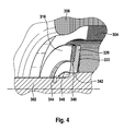
- FIG. 4 shows a detailed view of the disc with the friction lining.
- the annular friction lining 318 is arranged in the likewise annular recess 340 of the disc 320.
- the recess 340 is in an unspecified outer edge region of the disc 320, that is in the region of the radial periphery educated.
- Behind the disc 320 is the compression spring 322.
- the disc 320 further has a disc bore 342, which is provided on the inside with a disc toothing 344, which is at least partially positively engageable with an outside lamellar toothing 346 of the armature shaft 302 into engagement. As a result, the disc 320 is secured to the friction lining 318 rotationally fixed on the armature shaft 302.
Landscapes
- Engineering & Computer Science (AREA)
- Power Engineering (AREA)
- Chemical & Material Sciences (AREA)
- Combustion & Propulsion (AREA)
- Mechanical Engineering (AREA)
- General Engineering & Computer Science (AREA)
- Connection Of Motors, Electrical Generators, Mechanical Devices, And The Like (AREA)
Applications Claiming Priority (1)
| Application Number | Priority Date | Filing Date | Title |
|---|---|---|---|
| DE102010064249A DE102010064249A1 (de) | 2010-12-28 | 2010-12-28 | Anker für einen Elektromotor zum Antrieb einer Startervorrichtung |
Publications (2)
| Publication Number | Publication Date |
|---|---|
| EP2472099A1 true EP2472099A1 (fr) | 2012-07-04 |
| EP2472099B1 EP2472099B1 (fr) | 2020-02-05 |
Family
ID=45318911
Family Applications (1)
| Application Number | Title | Priority Date | Filing Date |
|---|---|---|---|
| EP11192290.2A Not-in-force EP2472099B1 (fr) | 2010-12-28 | 2011-12-07 | Armature pour un moteur électrique pour l'entraînement d'un dispositif de démarrage |
Country Status (4)
| Country | Link |
|---|---|
| EP (1) | EP2472099B1 (fr) |
| CN (1) | CN102545472A (fr) |
| DE (1) | DE102010064249A1 (fr) |
| HU (1) | HUE049396T2 (fr) |
Cited By (2)
| Publication number | Priority date | Publication date | Assignee | Title |
|---|---|---|---|---|
| EP2668393B1 (fr) * | 2011-01-26 | 2020-09-02 | SEG Automotive Germany GmbH | Dispositif de démarrage avec protection de surcharge |
| US20240116642A1 (en) * | 2022-10-06 | 2024-04-11 | Archer Aviation Inc. | Systems and methods for, and components of, gearboxes for evtol aircraft |
Families Citing this family (7)
| Publication number | Priority date | Publication date | Assignee | Title |
|---|---|---|---|---|
| CN106374656B (zh) * | 2016-11-08 | 2019-01-15 | 天津深之蓝海洋设备科技有限公司 | 一种分离式电机转子转轴、rov推进器电机、rov推进器及rov |
| CN106428483B (zh) * | 2016-11-08 | 2018-02-06 | 天津深之蓝海洋设备科技有限公司 | 一种rov推进器及rov |
| CN107565788A (zh) * | 2017-08-30 | 2018-01-09 | 华中科技大学 | 一种变极永磁直流起动发电机 |
| DE102020104019A1 (de) | 2020-02-17 | 2021-08-19 | Schaeffler Technologies AG & Co. KG | Rotorwelle mit Überlastschutz |
| DE102020106611A1 (de) | 2020-03-11 | 2021-09-16 | Schaeffler Technologies AG & Co. KG | Wellenanordnung und Getriebe mit Überlastschutz |
| DE102020119718A1 (de) | 2020-07-27 | 2021-07-22 | Schaeffler Technologies AG & Co. KG | Wellenanordnung für einen Antriebsstrang sowie Antriebsstrang mit der Wellenanordnung |
| CN112350509B (zh) * | 2020-09-30 | 2023-05-02 | 浙江双鸟机械有限公司 | 一种防止起升电机定转子错位的环链电动葫芦用限载装置 |
Citations (8)
| Publication number | Priority date | Publication date | Assignee | Title |
|---|---|---|---|---|
| BE367839A (fr) * | ||||
| DE2205235A1 (de) | 1972-02-04 | 1973-08-09 | Bosch Gmbh Robert | Lamellenkupplung, insbesondere fuer elektrische andrehvorrichtungen von brennkraftmaschinen |
| DE2337260A1 (de) | 1973-07-21 | 1975-02-06 | Bosch Gmbh Robert | Schraubtrieb an andrehvorrichtungen fuer brennkraftmaschinen |
| JPH03229966A (ja) * | 1989-12-21 | 1991-10-11 | Nippondenso Co Ltd | スタータ |
| US5241871A (en) | 1992-10-23 | 1993-09-07 | United Technologies Motor Systems, Inc. | Torque limiting starter drive clutch assembly |
| FR2803125A1 (fr) | 1999-12-23 | 2001-06-29 | Thomson Csf | Generatrice-demarreur a courant continu |
| DE10148670A1 (de) | 2001-10-02 | 2003-04-17 | Bosch Gmbh Robert | Startvorrichtung |
| FR2929462A1 (fr) * | 2008-03-26 | 2009-10-02 | Valeo Equip Electr Moteur | Arbre de rotor destine a assurer une liaison mecanique avec un reducteur de vitesses d'une machine electrique tournante |
Family Cites Families (7)
| Publication number | Priority date | Publication date | Assignee | Title |
|---|---|---|---|---|
| US2546448A (en) * | 1949-08-18 | 1951-03-27 | Bendix Aviat Corp | Generator |
| US3555317A (en) * | 1969-05-01 | 1971-01-12 | Motion Rotators Inc | Electric motor and clutch |
| JPH0678495A (ja) * | 1992-07-09 | 1994-03-18 | Nippondenso Co Ltd | 衝撃トルク吸収装置 |
| CN1151596C (zh) * | 2000-07-12 | 2004-05-26 | 北京东方渴望科技发展有限公司 | 洗衣机动力直驱装置 |
| CN2460789Y (zh) * | 2001-01-20 | 2001-11-21 | 席星航 | 外摩擦启动自动卸载式超越离合器启动装置 |
| JP2004183559A (ja) * | 2002-12-03 | 2004-07-02 | Mitsubishi Electric Corp | エンジン始動装置 |
| FR2870894B1 (fr) * | 2004-05-25 | 2008-11-14 | Valeo Equip Electr Moteur | Demarreur de vehicule automobile equipe d'un lanceur a roue libre par friction |
-
2010
- 2010-12-28 DE DE102010064249A patent/DE102010064249A1/de not_active Withdrawn
-
2011
- 2011-12-07 EP EP11192290.2A patent/EP2472099B1/fr not_active Not-in-force
- 2011-12-07 HU HUE11192290A patent/HUE049396T2/hu unknown
- 2011-12-26 CN CN2011104612446A patent/CN102545472A/zh active Pending
Patent Citations (8)
| Publication number | Priority date | Publication date | Assignee | Title |
|---|---|---|---|---|
| BE367839A (fr) * | ||||
| DE2205235A1 (de) | 1972-02-04 | 1973-08-09 | Bosch Gmbh Robert | Lamellenkupplung, insbesondere fuer elektrische andrehvorrichtungen von brennkraftmaschinen |
| DE2337260A1 (de) | 1973-07-21 | 1975-02-06 | Bosch Gmbh Robert | Schraubtrieb an andrehvorrichtungen fuer brennkraftmaschinen |
| JPH03229966A (ja) * | 1989-12-21 | 1991-10-11 | Nippondenso Co Ltd | スタータ |
| US5241871A (en) | 1992-10-23 | 1993-09-07 | United Technologies Motor Systems, Inc. | Torque limiting starter drive clutch assembly |
| FR2803125A1 (fr) | 1999-12-23 | 2001-06-29 | Thomson Csf | Generatrice-demarreur a courant continu |
| DE10148670A1 (de) | 2001-10-02 | 2003-04-17 | Bosch Gmbh Robert | Startvorrichtung |
| FR2929462A1 (fr) * | 2008-03-26 | 2009-10-02 | Valeo Equip Electr Moteur | Arbre de rotor destine a assurer une liaison mecanique avec un reducteur de vitesses d'une machine electrique tournante |
Cited By (3)
| Publication number | Priority date | Publication date | Assignee | Title |
|---|---|---|---|---|
| EP2668393B1 (fr) * | 2011-01-26 | 2020-09-02 | SEG Automotive Germany GmbH | Dispositif de démarrage avec protection de surcharge |
| US20240116642A1 (en) * | 2022-10-06 | 2024-04-11 | Archer Aviation Inc. | Systems and methods for, and components of, gearboxes for evtol aircraft |
| US12459633B2 (en) * | 2022-10-06 | 2025-11-04 | Archer Aviation Inc. | Systems and methods for, and components of, gearboxes for eVTOL aircraft |
Also Published As
| Publication number | Publication date |
|---|---|
| CN102545472A (zh) | 2012-07-04 |
| EP2472099B1 (fr) | 2020-02-05 |
| DE102010064249A1 (de) | 2012-06-28 |
| HUE049396T2 (hu) | 2020-09-28 |
Similar Documents
| Publication | Publication Date | Title |
|---|---|---|
| EP2472099B1 (fr) | Armature pour un moteur électrique pour l'entraînement d'un dispositif de démarrage | |
| DE102008000883A1 (de) | Startvorrichtung | |
| DE3141843A1 (de) | Elektrischer schraubtrieb-anlasser fuer brennkraftmaschinen | |
| DE102011017534B4 (de) | Startvorrichtung für eine Brennkraftmaschine | |
| DE102007026078A1 (de) | System aus Startvorrichtung und Brennkraftmaschine, Startvorrichtung sowie Brennkraftmaschine | |
| DE102010003431B4 (de) | Startvorrichtung mit Hohlrad- und Zwischenlagerdämpfung | |
| DE102010041797A1 (de) | Starter für eine Brennkraftmaschine | |
| EP2649300A2 (fr) | Dispositif de démarrage | |
| EP2172645B1 (fr) | Dispositif de démarrage | |
| EP2668393B1 (fr) | Dispositif de démarrage avec protection de surcharge | |
| EP2436913A1 (fr) | Démarreur pour moteur à combustion interne | |
| DE102010028415B4 (de) | Freilauf mit integrierter Dämpfung | |
| EP1300926A2 (fr) | Dispositif de démarrage | |
| DE102010041691B4 (de) | Startervorrichtung für Brennkraftmaschinen | |
| DE102010064242B4 (de) | Vorrichtung zur Sicherung eines Ritzels | |
| DE102011003184B4 (de) | Startvorrichtung mit geräuschgedämpftem Vorspuraktuator | |
| DE102013226927A1 (de) | Freilauf mit Rutschkupplung | |
| EP2390492A2 (fr) | Machine électrique dotée d'un accouplement à patinage | |
| WO2010145876A1 (fr) | Utilisation d'un dispositif de démarrage | |
| DE102012203490A1 (de) | Starter für eine Brennkraftmaschine | |
| DE102013225869B4 (de) | Freilaufeinrichtung für eine Startvorrichtung | |
| EP2655862A2 (fr) | Dispositif de démarrage insonorisé | |
| DE102010040527A1 (de) | Starter für eine Brennkraftmaschine |
Legal Events
| Date | Code | Title | Description |
|---|---|---|---|
| AK | Designated contracting states |
Kind code of ref document: A1 Designated state(s): AL AT BE BG CH CY CZ DE DK EE ES FI FR GB GR HR HU IE IS IT LI LT LU LV MC MK MT NL NO PL PT RO RS SE SI SK SM TR |
|
| AX | Request for extension of the european patent |
Extension state: BA ME |
|
| PUAI | Public reference made under article 153(3) epc to a published international application that has entered the european phase |
Free format text: ORIGINAL CODE: 0009012 |
|
| 17P | Request for examination filed |
Effective date: 20130104 |
|
| RAP1 | Party data changed (applicant data changed or rights of an application transferred) |
Owner name: SEG AUTOMOTIVE GERMANY GMBH |
|
| REG | Reference to a national code |
Ref country code: DE Ref legal event code: R079 Ref document number: 502011016431 Country of ref document: DE Free format text: PREVIOUS MAIN CLASS: F02N0015020000 Ipc: F02N0015000000 |
|
| GRAP | Despatch of communication of intention to grant a patent |
Free format text: ORIGINAL CODE: EPIDOSNIGR1 |
|
| STAA | Information on the status of an ep patent application or granted ep patent |
Free format text: STATUS: GRANT OF PATENT IS INTENDED |
|
| RIC1 | Information provided on ipc code assigned before grant |
Ipc: H02K 7/108 20060101ALI20190619BHEP Ipc: F02N 15/02 20060101ALI20190619BHEP Ipc: H02K 7/118 20060101ALN20190619BHEP Ipc: H02K 13/00 20060101ALI20190619BHEP Ipc: F02N 15/00 20060101AFI20190619BHEP Ipc: F02N 11/00 20060101ALN20190619BHEP |
|
| INTG | Intention to grant announced |
Effective date: 20190724 |
|
| GRAS | Grant fee paid |
Free format text: ORIGINAL CODE: EPIDOSNIGR3 |
|
| GRAA | (expected) grant |
Free format text: ORIGINAL CODE: 0009210 |
|
| STAA | Information on the status of an ep patent application or granted ep patent |
Free format text: STATUS: THE PATENT HAS BEEN GRANTED |
|
| AK | Designated contracting states |
Kind code of ref document: B1 Designated state(s): AL AT BE BG CH CY CZ DE DK EE ES FI FR GB GR HR HU IE IS IT LI LT LU LV MC MK MT NL NO PL PT RO RS SE SI SK SM TR |
|
| REG | Reference to a national code |
Ref country code: GB Ref legal event code: FG4D Free format text: NOT ENGLISH |
|
| REG | Reference to a national code |
Ref country code: AT Ref legal event code: REF Ref document number: 1230076 Country of ref document: AT Kind code of ref document: T Effective date: 20200215 |
|
| REG | Reference to a national code |
Ref country code: DE Ref legal event code: R096 Ref document number: 502011016431 Country of ref document: DE |
|
| REG | Reference to a national code |
Ref country code: IE Ref legal event code: FG4D Free format text: LANGUAGE OF EP DOCUMENT: GERMAN |
|
| REG | Reference to a national code |
Ref country code: CH Ref legal event code: EP |
|
| REG | Reference to a national code |
Ref country code: NL Ref legal event code: MP Effective date: 20200205 |
|
| PG25 | Lapsed in a contracting state [announced via postgrant information from national office to epo] |
Ref country code: PT Free format text: LAPSE BECAUSE OF FAILURE TO SUBMIT A TRANSLATION OF THE DESCRIPTION OR TO PAY THE FEE WITHIN THE PRESCRIBED TIME-LIMIT Effective date: 20200628 Ref country code: RS Free format text: LAPSE BECAUSE OF FAILURE TO SUBMIT A TRANSLATION OF THE DESCRIPTION OR TO PAY THE FEE WITHIN THE PRESCRIBED TIME-LIMIT Effective date: 20200205 Ref country code: FI Free format text: LAPSE BECAUSE OF FAILURE TO SUBMIT A TRANSLATION OF THE DESCRIPTION OR TO PAY THE FEE WITHIN THE PRESCRIBED TIME-LIMIT Effective date: 20200205 Ref country code: NO Free format text: LAPSE BECAUSE OF FAILURE TO SUBMIT A TRANSLATION OF THE DESCRIPTION OR TO PAY THE FEE WITHIN THE PRESCRIBED TIME-LIMIT Effective date: 20200505 |
|
| REG | Reference to a national code |
Ref country code: LT Ref legal event code: MG4D |
|
| PG25 | Lapsed in a contracting state [announced via postgrant information from national office to epo] |
Ref country code: HR Free format text: LAPSE BECAUSE OF FAILURE TO SUBMIT A TRANSLATION OF THE DESCRIPTION OR TO PAY THE FEE WITHIN THE PRESCRIBED TIME-LIMIT Effective date: 20200205 Ref country code: GR Free format text: LAPSE BECAUSE OF FAILURE TO SUBMIT A TRANSLATION OF THE DESCRIPTION OR TO PAY THE FEE WITHIN THE PRESCRIBED TIME-LIMIT Effective date: 20200506 Ref country code: LV Free format text: LAPSE BECAUSE OF FAILURE TO SUBMIT A TRANSLATION OF THE DESCRIPTION OR TO PAY THE FEE WITHIN THE PRESCRIBED TIME-LIMIT Effective date: 20200205 Ref country code: SE Free format text: LAPSE BECAUSE OF FAILURE TO SUBMIT A TRANSLATION OF THE DESCRIPTION OR TO PAY THE FEE WITHIN THE PRESCRIBED TIME-LIMIT Effective date: 20200205 Ref country code: IS Free format text: LAPSE BECAUSE OF FAILURE TO SUBMIT A TRANSLATION OF THE DESCRIPTION OR TO PAY THE FEE WITHIN THE PRESCRIBED TIME-LIMIT Effective date: 20200605 Ref country code: BG Free format text: LAPSE BECAUSE OF FAILURE TO SUBMIT A TRANSLATION OF THE DESCRIPTION OR TO PAY THE FEE WITHIN THE PRESCRIBED TIME-LIMIT Effective date: 20200505 |
|
| REG | Reference to a national code |
Ref country code: HU Ref legal event code: AG4A Ref document number: E049396 Country of ref document: HU |
|
| PG25 | Lapsed in a contracting state [announced via postgrant information from national office to epo] |
Ref country code: NL Free format text: LAPSE BECAUSE OF FAILURE TO SUBMIT A TRANSLATION OF THE DESCRIPTION OR TO PAY THE FEE WITHIN THE PRESCRIBED TIME-LIMIT Effective date: 20200205 |
|
| PG25 | Lapsed in a contracting state [announced via postgrant information from national office to epo] |
Ref country code: CZ Free format text: LAPSE BECAUSE OF FAILURE TO SUBMIT A TRANSLATION OF THE DESCRIPTION OR TO PAY THE FEE WITHIN THE PRESCRIBED TIME-LIMIT Effective date: 20200205 Ref country code: RO Free format text: LAPSE BECAUSE OF FAILURE TO SUBMIT A TRANSLATION OF THE DESCRIPTION OR TO PAY THE FEE WITHIN THE PRESCRIBED TIME-LIMIT Effective date: 20200205 Ref country code: ES Free format text: LAPSE BECAUSE OF FAILURE TO SUBMIT A TRANSLATION OF THE DESCRIPTION OR TO PAY THE FEE WITHIN THE PRESCRIBED TIME-LIMIT Effective date: 20200205 Ref country code: SM Free format text: LAPSE BECAUSE OF FAILURE TO SUBMIT A TRANSLATION OF THE DESCRIPTION OR TO PAY THE FEE WITHIN THE PRESCRIBED TIME-LIMIT Effective date: 20200205 Ref country code: EE Free format text: LAPSE BECAUSE OF FAILURE TO SUBMIT A TRANSLATION OF THE DESCRIPTION OR TO PAY THE FEE WITHIN THE PRESCRIBED TIME-LIMIT Effective date: 20200205 Ref country code: DK Free format text: LAPSE BECAUSE OF FAILURE TO SUBMIT A TRANSLATION OF THE DESCRIPTION OR TO PAY THE FEE WITHIN THE PRESCRIBED TIME-LIMIT Effective date: 20200205 Ref country code: LT Free format text: LAPSE BECAUSE OF FAILURE TO SUBMIT A TRANSLATION OF THE DESCRIPTION OR TO PAY THE FEE WITHIN THE PRESCRIBED TIME-LIMIT Effective date: 20200205 Ref country code: SK Free format text: LAPSE BECAUSE OF FAILURE TO SUBMIT A TRANSLATION OF THE DESCRIPTION OR TO PAY THE FEE WITHIN THE PRESCRIBED TIME-LIMIT Effective date: 20200205 |
|
| REG | Reference to a national code |
Ref country code: DE Ref legal event code: R097 Ref document number: 502011016431 Country of ref document: DE |
|
| PLBE | No opposition filed within time limit |
Free format text: ORIGINAL CODE: 0009261 |
|
| STAA | Information on the status of an ep patent application or granted ep patent |
Free format text: STATUS: NO OPPOSITION FILED WITHIN TIME LIMIT |
|
| 26N | No opposition filed |
Effective date: 20201106 |
|
| PG25 | Lapsed in a contracting state [announced via postgrant information from national office to epo] |
Ref country code: IT Free format text: LAPSE BECAUSE OF FAILURE TO SUBMIT A TRANSLATION OF THE DESCRIPTION OR TO PAY THE FEE WITHIN THE PRESCRIBED TIME-LIMIT Effective date: 20200205 |
|
| PG25 | Lapsed in a contracting state [announced via postgrant information from national office to epo] |
Ref country code: SI Free format text: LAPSE BECAUSE OF FAILURE TO SUBMIT A TRANSLATION OF THE DESCRIPTION OR TO PAY THE FEE WITHIN THE PRESCRIBED TIME-LIMIT Effective date: 20200205 Ref country code: PL Free format text: LAPSE BECAUSE OF FAILURE TO SUBMIT A TRANSLATION OF THE DESCRIPTION OR TO PAY THE FEE WITHIN THE PRESCRIBED TIME-LIMIT Effective date: 20200205 |
|
| REG | Reference to a national code |
Ref country code: CH Ref legal event code: PL |
|
| GBPC | Gb: european patent ceased through non-payment of renewal fee |
Effective date: 20201207 |
|
| PG25 | Lapsed in a contracting state [announced via postgrant information from national office to epo] |
Ref country code: MC Free format text: LAPSE BECAUSE OF FAILURE TO SUBMIT A TRANSLATION OF THE DESCRIPTION OR TO PAY THE FEE WITHIN THE PRESCRIBED TIME-LIMIT Effective date: 20200205 |
|
| REG | Reference to a national code |
Ref country code: BE Ref legal event code: MM Effective date: 20201231 |
|
| PG25 | Lapsed in a contracting state [announced via postgrant information from national office to epo] |
Ref country code: LU Free format text: LAPSE BECAUSE OF NON-PAYMENT OF DUE FEES Effective date: 20201207 Ref country code: IE Free format text: LAPSE BECAUSE OF NON-PAYMENT OF DUE FEES Effective date: 20201207 |
|
| PG25 | Lapsed in a contracting state [announced via postgrant information from national office to epo] |
Ref country code: CH Free format text: LAPSE BECAUSE OF NON-PAYMENT OF DUE FEES Effective date: 20201231 Ref country code: GB Free format text: LAPSE BECAUSE OF NON-PAYMENT OF DUE FEES Effective date: 20201207 Ref country code: LI Free format text: LAPSE BECAUSE OF NON-PAYMENT OF DUE FEES Effective date: 20201231 |
|
| REG | Reference to a national code |
Ref country code: DE Ref legal event code: R082 Ref document number: 502011016431 Country of ref document: DE Representative=s name: DEHNSGERMANY PARTNERSCHAFT VON PATENTANWAELTEN, DE Ref country code: DE Ref legal event code: R082 Ref document number: 502011016431 Country of ref document: DE Representative=s name: DEHNS GERMANY PARTNERSCHAFT MBB, DE |
|
| REG | Reference to a national code |
Ref country code: AT Ref legal event code: MM01 Ref document number: 1230076 Country of ref document: AT Kind code of ref document: T Effective date: 20201207 |
|
| PG25 | Lapsed in a contracting state [announced via postgrant information from national office to epo] |
Ref country code: AT Free format text: LAPSE BECAUSE OF NON-PAYMENT OF DUE FEES Effective date: 20201207 |
|
| PG25 | Lapsed in a contracting state [announced via postgrant information from national office to epo] |
Ref country code: TR Free format text: LAPSE BECAUSE OF FAILURE TO SUBMIT A TRANSLATION OF THE DESCRIPTION OR TO PAY THE FEE WITHIN THE PRESCRIBED TIME-LIMIT Effective date: 20200205 Ref country code: MT Free format text: LAPSE BECAUSE OF FAILURE TO SUBMIT A TRANSLATION OF THE DESCRIPTION OR TO PAY THE FEE WITHIN THE PRESCRIBED TIME-LIMIT Effective date: 20200205 Ref country code: CY Free format text: LAPSE BECAUSE OF FAILURE TO SUBMIT A TRANSLATION OF THE DESCRIPTION OR TO PAY THE FEE WITHIN THE PRESCRIBED TIME-LIMIT Effective date: 20200205 |
|
| PG25 | Lapsed in a contracting state [announced via postgrant information from national office to epo] |
Ref country code: MK Free format text: LAPSE BECAUSE OF FAILURE TO SUBMIT A TRANSLATION OF THE DESCRIPTION OR TO PAY THE FEE WITHIN THE PRESCRIBED TIME-LIMIT Effective date: 20200205 Ref country code: AL Free format text: LAPSE BECAUSE OF FAILURE TO SUBMIT A TRANSLATION OF THE DESCRIPTION OR TO PAY THE FEE WITHIN THE PRESCRIBED TIME-LIMIT Effective date: 20200205 |
|
| PG25 | Lapsed in a contracting state [announced via postgrant information from national office to epo] |
Ref country code: BE Free format text: LAPSE BECAUSE OF NON-PAYMENT OF DUE FEES Effective date: 20201231 |
|
| PGFP | Annual fee paid to national office [announced via postgrant information from national office to epo] |
Ref country code: FR Payment date: 20221214 Year of fee payment: 12 Ref country code: DE Payment date: 20220623 Year of fee payment: 12 |
|
| PGFP | Annual fee paid to national office [announced via postgrant information from national office to epo] |
Ref country code: HU Payment date: 20221130 Year of fee payment: 12 |
|
| REG | Reference to a national code |
Ref country code: DE Ref legal event code: R119 Ref document number: 502011016431 Country of ref document: DE |
|
| PG25 | Lapsed in a contracting state [announced via postgrant information from national office to epo] |
Ref country code: DE Free format text: LAPSE BECAUSE OF NON-PAYMENT OF DUE FEES Effective date: 20240702 |
|
| PG25 | Lapsed in a contracting state [announced via postgrant information from national office to epo] |
Ref country code: FR Free format text: LAPSE BECAUSE OF NON-PAYMENT OF DUE FEES Effective date: 20231231 |
|
| PG25 | Lapsed in a contracting state [announced via postgrant information from national office to epo] |
Ref country code: HU Free format text: LAPSE BECAUSE OF NON-PAYMENT OF DUE FEES Effective date: 20231208 |
|
| PG25 | Lapsed in a contracting state [announced via postgrant information from national office to epo] |
Ref country code: HU Free format text: LAPSE BECAUSE OF NON-PAYMENT OF DUE FEES Effective date: 20231208 Ref country code: FR Free format text: LAPSE BECAUSE OF NON-PAYMENT OF DUE FEES Effective date: 20231231 Ref country code: DE Free format text: LAPSE BECAUSE OF NON-PAYMENT OF DUE FEES Effective date: 20240702 |