EP2474438B1 - Appareil de coulissement de siège pour véhicule - Google Patents
Appareil de coulissement de siège pour véhicule Download PDFInfo
- Publication number
- EP2474438B1 EP2474438B1 EP10813665.6A EP10813665A EP2474438B1 EP 2474438 B1 EP2474438 B1 EP 2474438B1 EP 10813665 A EP10813665 A EP 10813665A EP 2474438 B1 EP2474438 B1 EP 2474438B1
- Authority
- EP
- European Patent Office
- Prior art keywords
- motor
- seat
- rails
- gear
- fixed
- Prior art date
- Legal status (The legal status is an assumption and is not a legal conclusion. Google has not performed a legal analysis and makes no representation as to the accuracy of the status listed.)
- Not-in-force
Links
- 230000005540 biological transmission Effects 0.000 claims description 42
- 230000002787 reinforcement Effects 0.000 claims description 36
- 230000007246 mechanism Effects 0.000 claims description 32
- 230000008859 change Effects 0.000 claims description 5
- 239000000758 substrate Substances 0.000 description 16
- 210000000078 claw Anatomy 0.000 description 5
- 230000007423 decrease Effects 0.000 description 5
- 239000003638 chemical reducing agent Substances 0.000 description 4
- 230000002093 peripheral effect Effects 0.000 description 4
- 230000003247 decreasing effect Effects 0.000 description 3
- 239000000463 material Substances 0.000 description 3
- 238000004519 manufacturing process Methods 0.000 description 2
- 239000002184 metal Substances 0.000 description 2
- 230000009467 reduction Effects 0.000 description 2
- 239000011347 resin Substances 0.000 description 2
- 229920005989 resin Polymers 0.000 description 2
- 230000035807 sensation Effects 0.000 description 2
- 230000004044 response Effects 0.000 description 1
- 238000005096 rolling process Methods 0.000 description 1
Images

Classifications
-
- B—PERFORMING OPERATIONS; TRANSPORTING
- B60—VEHICLES IN GENERAL
- B60N—SEATS SPECIALLY ADAPTED FOR VEHICLES; VEHICLE PASSENGER ACCOMMODATION NOT OTHERWISE PROVIDED FOR
- B60N2/00—Seats specially adapted for vehicles; Arrangement or mounting of seats in vehicles
- B60N2/02—Seats specially adapted for vehicles; Arrangement or mounting of seats in vehicles the seat or part thereof being movable, e.g. adjustable
- B60N2/04—Seats specially adapted for vehicles; Arrangement or mounting of seats in vehicles the seat or part thereof being movable, e.g. adjustable the whole seat being movable
- B60N2/06—Seats specially adapted for vehicles; Arrangement or mounting of seats in vehicles the seat or part thereof being movable, e.g. adjustable the whole seat being movable slidable
-
- B—PERFORMING OPERATIONS; TRANSPORTING
- B60—VEHICLES IN GENERAL
- B60N—SEATS SPECIALLY ADAPTED FOR VEHICLES; VEHICLE PASSENGER ACCOMMODATION NOT OTHERWISE PROVIDED FOR
- B60N2/00—Seats specially adapted for vehicles; Arrangement or mounting of seats in vehicles
- B60N2/02—Seats specially adapted for vehicles; Arrangement or mounting of seats in vehicles the seat or part thereof being movable, e.g. adjustable
- B60N2/04—Seats specially adapted for vehicles; Arrangement or mounting of seats in vehicles the seat or part thereof being movable, e.g. adjustable the whole seat being movable
- B60N2/06—Seats specially adapted for vehicles; Arrangement or mounting of seats in vehicles the seat or part thereof being movable, e.g. adjustable the whole seat being movable slidable
- B60N2/067—Seats specially adapted for vehicles; Arrangement or mounting of seats in vehicles the seat or part thereof being movable, e.g. adjustable the whole seat being movable slidable by linear actuators, e.g. linear screw mechanisms
-
- B—PERFORMING OPERATIONS; TRANSPORTING
- B60—VEHICLES IN GENERAL
- B60N—SEATS SPECIALLY ADAPTED FOR VEHICLES; VEHICLE PASSENGER ACCOMMODATION NOT OTHERWISE PROVIDED FOR
- B60N2/00—Seats specially adapted for vehicles; Arrangement or mounting of seats in vehicles
- B60N2/02—Seats specially adapted for vehicles; Arrangement or mounting of seats in vehicles the seat or part thereof being movable, e.g. adjustable
- B60N2/0224—Non-manual adjustments, e.g. with electrical operation
- B60N2/02246—Electric motors therefor
-
- B—PERFORMING OPERATIONS; TRANSPORTING
- B60—VEHICLES IN GENERAL
- B60N—SEATS SPECIALLY ADAPTED FOR VEHICLES; VEHICLE PASSENGER ACCOMMODATION NOT OTHERWISE PROVIDED FOR
- B60N2/00—Seats specially adapted for vehicles; Arrangement or mounting of seats in vehicles
- B60N2/02—Seats specially adapted for vehicles; Arrangement or mounting of seats in vehicles the seat or part thereof being movable, e.g. adjustable
- B60N2/0224—Non-manual adjustments, e.g. with electrical operation
- B60N2/02246—Electric motors therefor
- B60N2/02253—Electric motors therefor characterised by the transmission between the electric motor and the seat or seat parts
-
- B—PERFORMING OPERATIONS; TRANSPORTING
- B60—VEHICLES IN GENERAL
- B60N—SEATS SPECIALLY ADAPTED FOR VEHICLES; VEHICLE PASSENGER ACCOMMODATION NOT OTHERWISE PROVIDED FOR
- B60N2/00—Seats specially adapted for vehicles; Arrangement or mounting of seats in vehicles
- B60N2/02—Seats specially adapted for vehicles; Arrangement or mounting of seats in vehicles the seat or part thereof being movable, e.g. adjustable
- B60N2/0224—Non-manual adjustments, e.g. with electrical operation
- B60N2/02246—Electric motors therefor
- B60N2/02258—Electric motors therefor characterised by the mounting of the electric motor for adjusting the seat
-
- B—PERFORMING OPERATIONS; TRANSPORTING
- B60—VEHICLES IN GENERAL
- B60N—SEATS SPECIALLY ADAPTED FOR VEHICLES; VEHICLE PASSENGER ACCOMMODATION NOT OTHERWISE PROVIDED FOR
- B60N2/00—Seats specially adapted for vehicles; Arrangement or mounting of seats in vehicles
- B60N2/02—Seats specially adapted for vehicles; Arrangement or mounting of seats in vehicles the seat or part thereof being movable, e.g. adjustable
- B60N2/0224—Non-manual adjustments, e.g. with electrical operation
- B60N2/0226—User interfaces specially adapted for seat adjustment
- B60N2/0228—Hand-activated mechanical switches
-
- B—PERFORMING OPERATIONS; TRANSPORTING
- B60—VEHICLES IN GENERAL
- B60N—SEATS SPECIALLY ADAPTED FOR VEHICLES; VEHICLE PASSENGER ACCOMMODATION NOT OTHERWISE PROVIDED FOR
- B60N2/00—Seats specially adapted for vehicles; Arrangement or mounting of seats in vehicles
- B60N2/02—Seats specially adapted for vehicles; Arrangement or mounting of seats in vehicles the seat or part thereof being movable, e.g. adjustable
- B60N2/04—Seats specially adapted for vehicles; Arrangement or mounting of seats in vehicles the seat or part thereof being movable, e.g. adjustable the whole seat being movable
- B60N2/06—Seats specially adapted for vehicles; Arrangement or mounting of seats in vehicles the seat or part thereof being movable, e.g. adjustable the whole seat being movable slidable
- B60N2/07—Slide construction
-
- B—PERFORMING OPERATIONS; TRANSPORTING
- B60—VEHICLES IN GENERAL
- B60N—SEATS SPECIALLY ADAPTED FOR VEHICLES; VEHICLE PASSENGER ACCOMMODATION NOT OTHERWISE PROVIDED FOR
- B60N2230/00—Communication or electronic aspects
- B60N2230/10—Wired data transmission
Definitions
- the present invention relates to a seat sliding apparatus for vehicles, which adjusts the position of a seat in the forward-rearward direction with respect to the floor of a vehicle by actuating a motor in response to manipulation of a manipulation switch.
- Japanese Laid-Open Patent Publication No. 8-335422 discloses a manipulation switch usable in a seat sliding apparatus for vehicles.
- the manipulation switch is arranged in a side cover, or, in other words, a seat side shield, which is mounted on a side surface of the seating portion of a seat in a vehicle.
- a seat according to the preamble of claim 1 is known from EP 1 974 983 A2 and it may use a switch as known from the above mentioned japanese document.
- a seat sliding apparatus for vehicles includes a motor and a speed reducer for reducing the speed of rotation of the motor for improving operating accuracy of the seat sliding apparatus in operation.
- the motor and the speed reducer are arranged in the vicinity of the upper rails.
- a seat sliding apparatus for a vehicle includes a first pair of rails fixed to either one of a floor of a vehicle and a seat in the vehicle, a rail structure, a pair of nut members, a pair of screw shafts, a speed reducer, and a manipulation switch.
- the rail structure includes a second pair of rails fixed to the other one of the floor and the seat. The second rails are connected to the first rails in a manner movable relative to the first rails in a seat forward-rearward direction.
- Each of the nut members is fixed to one of the first rails, respectively.
- the speed reducer is equipped with a motor connected to the two screw shafts through a transmission mechanism to rotate the screw shafts.
- the speed reducer-equipped motor includes a motor, a gear mechanism, which is connected to a rotary shaft of the motor to reduce the speed of rotation of the motor, and a gear housing that rotationally supports the gear mechanism and is fixed to the rail structure such that the axis of an output shaft of the gear mechanism extends in a seat width direction.
- the manipulation switch actuates the speed reducer-equipped motor.
- the manipulation switch has a manipulating portion fixed to the gear housing and exposed at a forward end of the seat.
- the manipulation switch is electrically connected to the motor in the immediate proximity of the motor.
- This decreases the length of a wire harness necessary for connecting the manipulation switch to the motor.
- the size of the space needed for arranging the wire harness and the mass of the wire harness are prevented from being increased.
- the manipulating portion of the manipulation switch since the manipulating portion of the manipulation switch is exposed at a forward end of the seat, the manipulating portion may be reached and manipulated from in front of the seat.
- the sensation of manipulating the manipulating portion is thus similar to that of a manual seat sliding apparatus for vehicles, which adjusts the position of a seat in the forward-rearward direction in the vehicle through manual operation of a manipulation handle. Manipulation of the manipulating portion is thus facilitated.
- the rail structure preferably includes a reinforcement bracket that is fixed to front end portions of the two second rails to connect the second rails together in the seat width direction, and the gear housing is preferably fixed to the reinforcement bracket.
- the reinforcement bracket thus stably supports the gear housing, which supports a relatively great load, or, in other words, the gear mechanism. Since the manipulation switch is fixed to the gear housing, which is supported by the reinforcement bracket in this manner, the manipulation switch is allowed to stably receive manipulation load produced by the user.
- the above described seat sliding apparatus further includes a rotation sensor for detecting rotation of the motor, a control circuit that controls rotation of the motor based on the detected rotation, and a circuit case for accommodating the rotation sensor and the control circuit.
- the circuit case is fixed to the gear housing.
- the manipulation switch is preferably fixed to the gear housing through the circuit case and electrically connected to the motor through the control circuit.
- the manipulation switch is fixed to the gear housing through the circuit case.
- the manipulation switch is connected directly to the control circuit (a control circuit substrate), for example, and thus electrically connected to the motor. This simplifies the configuration for electrical connection between the manipulation switch and the control circuit and decreases the number of the manufacturing steps.
- the transmission mechanism preferably includes a transmission shaft, first pair of gears, second gears, and a pair of casings.
- the transmission shaft extends along the axis of the output shaft of the gear mechanism and is passed through the gear housing.
- the transmission shaft is connected to an output gear of the gear mechanism and is rotatable integrally with the output gear.
- the first pair of gears are connected to opposite end portions of the transmission shaft in a manner rotatable integrally with the transmission shaft.
- the second gears are connected to front end portions of the corresponding screw shafts and rotatable integrally with the screw shafts.
- Each of the second gears is meshed with the corresponding one of the first gears to change the orientation of the rotation axis of rotation of the first gear and to transmit the rotation of the first gear to the corresponding screw shaft.
- the casings are fixed to opposite end portions of the rail structure in the seat width direction. Each of the casings rotationally supports the corresponding one of the first gears and the associated one of the second gears.
- the transmission mechanism for transmitting rotation of the speed reducer-equipped motor to the two screw shafts is configured by the transmission shaft, the two first gears and the corresponding second gears, and the casings.
- transmission of rotation involving a direction change between the first and second gears is performed without substantially changing the speed through a simple configuration.
- This further reduces the size of each casing and thus the size of the rail cross section of each second rail.
- load acting between the first and second gears is decreased, the rigidity of each of the first and second gears may be further reduced. This improves flexibility in selection of the material for forming each gear.
- gear housing for supporting the gear mechanism and each casing for supporting the first and second gears are fixed to and integrated with the rail structure, rotation of the gear mechanism is transmitted to the two first gears and the corresponding second gears through the transmission shaft in a more stabilized state.
- the motor is preferably arranged such that the axis of the rotary shaft of the motor extends substantially in the forward-rearward direction, which is different from the seat width direction in which the axis of the transmission shaft extends.
- the motor is arranged such that the axis of the rotary shaft of the motor extends substantially in a vehicle forward-rearward direction.
- the motor the speed reducer-equipped motor
- the motor may be arranged in the space formed between the two second rails.
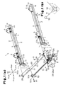
- Fig. 1 (a) is an exploded perspective view showing a seat sliding apparatus 1 for a vehicle according to the illustrated embodiment.
- the seat sliding apparatus 1 is used in a seat (not shown) mounted in a vehicle such as an automobile.
- the width direction (the leftward-rightward direction) and the forward-rearward direction of the seat correspond to the width direction and the forward-rearward direction of the vehicle, respectively.
- a pair of lower rails 3 serving as first rails are arranged on opposite sides in the seat width direction.
- the lower rails 3 are fixed to the floor of the vehicle and extend in the seat forward-rearward direction.
- a pair of upper rails 4 serving as second rails are arranged on opposite sides in the seat width direction.
- Each one of the upper rails 4 is mounted on the corresponding one of the lower rails 3 and is movable relative to the lower rail 3 in the seat forward-rearward direction.
- Each of the lower rails 3 has a pair of side wall portions 11, a bottom wall portion 12, and a pair of folded wall portions 13, which are formed as an integral body in a manner continuous from one another.
- the side wall portions 11 extend upward from opposite sides of the bottom wall portion 12 in the width direction.
- the bottom wall portion 12 joins the basal ends (the lower ends) of the side wall portions 11 to each other.
- Each of the folded wall portions 13 extends inward from the distal end (the upper end) of the corresponding one of the side wall portions 11 in the width direction and is then folded toward the bottom wall portion 12.
- the lower rails 3 are fixed to the floor of the vehicle through a pair of leg brackets 5, which are fixedly attached to a front end portion and a rear end portion of the bottom wall portion 12.
- Each of the upper rails 4 has a pair of side wall portions 14, a top wall portion 15, and a pair of folded wall portions 16, which are formed as an integral body in a manner continuous from one another.
- the side wall portions 14 extend in the upward-downward direction at corresponding positions between the two folded wall portions 13 of the corresponding lower rail 3.
- the top wall portion 15 joins the basal ends (the upper ends) of the side wall portions 14 to each other.
- Each of the folded wall portions 16 extends outward from the distal end (the lower end) of the corresponding one of the side wall portions 14 in the width direction and is then folded in such a manner as to be surrounded by the wall portions 11 and the folded wall portions 13 of the corresponding lower rail 3.
- the lower rails 3 and the upper rails 4 each have a substantially U-shaped cross section.
- Each lower rail 3 and the corresponding upper rail 4 are arranged such that the opening of the lower rail 3 and the opening of the upper rail 4 face each other.
- Each lower rail 3 and the corresponding upper rail 4 are prevented from separating from each other in the upward-downward direction through engagement between the folded wall portions 13 and the folded wall portions 16.
- the rail cross section formed through engagement between the lower rail 3 and the upper rail 4 has a rectangular shape.
- Each lower rail 3 cooperates with the corresponding upper rail 4 to form an inner space.
- Each upper rail 4 is supported by a rolling element (not shown) arranged between the upper rail 4 and the corresponding lower rail 3 in a manner slidable with respect to the lower rail 3 in the longitudinal direction (the seat forward-rearward direction). Pairs of seat brackets 6 are attached to opposite ends of the top wall portion 15 of each upper rail 4 in the forward-rearward direction. Each upper rail 4 is fixed to a seat, which forms a seating portion for an occupant, through the two seat brackets 6. As a result, the position of the seat in the forward-rearward direction is adjusted with respect to the floor of the vehicle through movement of the upper rail 4 relative to the lower rail 3.
- Each upper rail 4 supports a round rod-like screw shaft 7, which is received in the inner space formed by the upper rail 4 and the corresponding lower rail 3.
- the screw shaft 7 extends in the seat forward-rearward direction, which is the sliding direction of the upper rail 4.
- the screw shaft 7 is supported rotationally with respect to the upper rail 4 but immovably in the axial direction.
- the supporting mode of the screw shaft 7 with respect to the upper rail 4 is not illustrated.
- Each of the screw shafts 7 has a threaded portion (an external thread) formed on an outer peripheral portion of the screw shaft 7 in accordance with a predetermined axial range.
- a nut member 9 having a threaded portion (an internal thread) which is engaged with the threaded portion of the corresponding screw shaft 7, is fixed to each lower rail 3.
- the screw shaft 7 moves integrally with the corresponding upper rail 4 relatively to the nut member 9 (the lower rail 3) in the forward-rearward direction. As has been described, this adjusts the position of the seat in the forward-rearward direction with respect to the floor of the vehicle.
- the screw shaft 7 stops to rotate, the screw shaft 7 is restricted from moving integrally with the upper rail 4 relative to the nut member 9 (the lower rails 3) in the forward-rearward direction. This restricts movement of the seat relative to the floor of the vehicle in the forward-rearward direction. The seat of the vehicle is thus maintained at a certain position in the forward-rearward direction.
- the reinforcement bracket 21 has a body wall portion 22 and a pair of flanges 23, which are formed integrally with one another.
- the body wall portion 22 extends in the seat width direction.
- the flanges 23 extend downward from the front end and the rear end of the body wall portion 22.
- the reinforcement bracket 21 is formed in such a shape that opposite end portions are raised with respect to a central portion in the seat width direction, or, in other words, has a moderate U shape as viewed in the forward-rearward direction.
- the reinforcement bracket 21 has U-shaped cutouts 24, each of which has an opening faced outward, at the opposite ends of the body wall portion 22 in the seat width direction. Pairs of bolt passing holes 25 are formed in distal end portions of the two flanges 23, which are located below each of the cutouts 24. Each pair of the bolt passing holes 25 are aligned on a line in the seat forward-rearward direction.
- the reinforcement bracket 21 also has a bolt passing hole 26, which is an opening facing both upward and downward, at a position to the left in the body wall portion 22.
- a speed reducer-equipped motor 30 is fixed to the reinforcement bracket 21.
- the speed reducer-equipped motor 30 includes a motor 31, a gear mechanism, and a gear housing 32.
- the gear mechanism is connected to the rotary shaft of the motor 31 and reduces rotation speed of the motor 31.
- the gear housing 32 rotationally supports the gear mechanism.
- the gear mechanism may be, for example, a worm gear, which is configured by a worm serving as an input gear fixedly attached to the rotary shaft of the motor 31 and a worm wheel serving as an output gear engaged with the worm.
- the speed reducer-equipped motor 30 is fixed to the reinforcement bracket 21 in the gear housing 32.
- the gear housing 32 has a housing portion 32a, which accommodates and supports the gear mechanism such that the axis of the worm wheel (the output shaft) extends in the seat width direction.
- the gear housing 32 has a shaft passing hole 32b, which extends through the housing portion 32a along the axis of the worm wheel.
- the gear housing 32 is made of, for example, resin material.
- the gear housing 32 also includes a block-shaped attachment portion 32c, which projects upward from the housing portion 32a.
- the width of the attachment portion 32c is slightly smaller than the distance between the two flanges 23 of the reinforcement bracket 21.
- An upper surface of the attachment portion 32c has a threaded hole 32d, which extends downward from the upper surface.
- the gear housing 32 has a tubular holder portion 32e, which extends rearward from the housing portion 32a.
- the motor 31 is engaged with the holder portion 32e with the rotary shaft of the motor 31 received in the holder portion 32e.
- the motor 31 is thus fixed to the gear housing 32.
- the axis of the rotary shaft of the motor 31, which extends substantially in the seat forward-rearward direction, or, in other words, the axis of the worm, does not coincide with the axis of the worm wheel (the output shaft).
- a circuit case 35 is fixed to the gear housing 32 and projects forward from the gear housing 32.
- the circuit case 35 includes an outer case 36 and an inner case 37, which are formed of resin or metal.
- the outer case 36 includes a pair of side wall portions 36a, 36b and an attachment wall 36c.
- the side wall portions 36a, 36b are spaced from each other in the seat width direction and face each other.
- the attachment wall 36c extends in the seat width direction to connect the front ends of the side wall portions 36a, 36b.
- the side wall portions 36a, 36b extend parallel to each other in the seat forward-rearward direction.
- the circuit case 35 is formed in a channel-like shape having an opening facing rearward.
- the opening width of the outer case 36 (the distance between the side wall portions 36a, 36b) is greater than the dimension of the gear housing 32 in the seat width direction.
- the circuit case 35 is fastened to the gear housing 32 through the side wall portions 36a, 36b.
- a control circuit substrate 42 having a control circuit 41 is held by the inner wall surface of the attachment wall 36c.
- the control circuit substrate 42 is electrically connected to a battery (not shown) mounted in the vehicle through a wire harness.
- the control circuit substrate 42 is electrically connected also to the motor 31 through another wire harness.
- the connection mode between the control circuit substrate 42 and the battery in the vehicle and the connection mode between the control circuit substrate 42 and the motor 31 are not illustrated herein.
- a rotary switch 43 which serves as a rotation sensor for detecting rotation of the motor 31, is held by the inner wall surface of the side wall portion 36a.
- the rotary switch 43 is wire-connected to the control circuit substrate 42 and electrically connected to the control circuit 41.
- the control circuit 41 controls rotation of the motor 31 based on the rotation of the motor 31 detected by the rotary switch 43.
- the inner case 37 is held by the inner surfaces of the outer case 36 in such a manner as to cover the control circuit substrate 42 and the rotary switch 43 at the corresponding positions between the inner case 37 and the outer case 36. In this manner, the control circuit substrate 42 and the rotary switch 43 are received in the circuit case 35 without being exposed to the exterior.
- a manipulation switch 38 which is manipulated to actuate the motor 31, is fixed to a front end portion (the attachment wall 36c) of the outer case 36.
- the manipulation switch 38 outputs a manipulation signal for moving the seat forward or rearward in the vehicle to the control circuit 41.
- the connection terminal of the manipulation switch 38 is passed through the attachment wall 36c and connected directly to the control circuit 41 (the control circuit substrate 42).
- the manipulation switch 38 has a manipulating portion 38a, which is exposed at a forward end of the seat in the vehicle so that the occupant seated on the seat can reach and manipulate the manipulation switch 38 from in front of the seat.
- a hexagonal rod-like transmission shaft 51 is passed through a shaft passing hole 32b, which is formed in the gear housing 32, immovably in the axial direction.
- the transmission shaft 51 is engaged with the worm wheel in a manner rotatable integrally with the worm wheel.
- the transmission shaft 51 extends along the axis of the worm wheel (the output shaft), or, in other words, in the seat width direction.
- An upper portion of the transmission shaft 51 is covered by the reinforcement bracket 21.
- a box-like casing 52 is fixed to the front end of each of the upper rails 4.
- the casings 52 are arranged between the flanges 23 at the opposite ends of the reinforcement bracket 21. Specifically, a fixing bracket 53 is fastened to the front end of each upper rail 4.
- a through hole 53a which is an opening that faces both forward and rearward in the seat at a position above the top wall portion 15, is formed in the fixing bracket 53.
- Each of the casings 52 has a pair of bolt passing holes 52a, each of which is an opening that is coaxial with the through hole 53a and the corresponding bolt passing holes 25 and faces both forward and rearward in the seat.
- a T-shaped engagement claw portion 52b which projects upward from the upper end of each casing 52 and is engaged with the peripheral portion of the corresponding cutout 24, is formed in an upper portion of the casing 52.
- the engagement claw portions 52b are engaged with the peripheral portions of the corresponding cutouts 24 and nuts are fastened to threaded portions of bolts B1, each of which is passed through the corresponding bolt passing holes 25, bolt passing hole 52a, and through hole 53a. This fixes each casing 52 to the corresponding upper rail 4 and the reinforcement bracket 21 at a position between the flanges 23 of the reinforcement bracket 21.
- each end portion of the transmission shaft 51 is engaged with a first gear 55, which is accommodated in the corresponding casing 52, in a manner rotatable integrally with the first gear 55.
- the front end portion of each screw shaft 7 projects forward from the associated upper rail 4 and is received in the corresponding casing 52.
- the front end portion of the screw shaft 7 is engaged with a second gear 56, which is received in the casing 52, in a manner rotatable integrally with the second gear 56.
- Each first gear 55 and the corresponding second gear 56 are rotationally supported by the associated casing 52, with the axis of the first gear 55 and the axis of the second gear 56 extending perpendicular to each other.
- the first gear 55 and the second gear 56 configure screw gears that are meshed with each other in the casing 52, thus changing the orientation of the axis of rotation of the first gear 55, which rotates integrally with the transmission shaft 51, without changing the speed of such rotation.
- the rotation of the first gear 55 is thus transmitted to the second gear 56 and the corresponding screw shaft 7.
- the transmission shaft 51, the two first gears 55 and the corresponding second gears 56, and the casings 52 configure a transmission mechanism 50.
- a manipulation signal for moving the seat forward or rearward in the vehicle is output to the control circuit 41.
- the transmission shaft 51 rotates integrally with the worm wheel received in the gear housing 32. This causes each pair of the screw gears, which are connected to the corresponding end portion of the transmission shaft 51, to change the orientation of the axis of rotation of the transmission shaft 51.
- the control circuit 41 suspends actuation of the motor 31. This stops rotation of the screw shafts 7, thus restricting movement of the upper rails 4 relative to the lower rails 3 in the seat forward-rearward direction in the above-described manner. As a result, the seat is maintained at a certain position in the forward-rearward direction in the vehicle.
- the illustrated embodiment has the advantages described below.
- a hook-like engagement claw may be projected upward from the gear housing 32 and a through hole with which the engagement claw is engaged may be formed in the reinforcement bracket 21.
- the gear housing 32 is fixed to the reinforcement bracket 21 by engaging the engagement claw with the peripheral portion of the through hole.
- each casing 52 may have a threaded hole, which extends downward from the upper end surface of the casing 52, and a bolt passing hole, which is an opening that faces both upward and downward, may be formed in the reinforcement bracket 21.
- the casing 52 is fixed to the reinforcement bracket 21 by passing a bolt through the bolt passing hole and then threading the threaded portion of the bolt onto the threaded hole to fasten the bolt.
- a connection terminal for feeding electric power to the motor 31 may be extended to a position in the vicinity of the control circuit substrate 42 and connected directly to the control circuit substrate 42.
- control circuit 41 the control circuit substrate 42, and the rotary switch 43 may be omitted.
- the motor 31 is rotated directly through manipulation of the manipulation switch 38.
- the circuit case 35 (the outer case 36 and the inner case 37) may be omitted and a switch box forming a casing for the manipulation switch 38 may be fixed directly to the gear housing 32.
- the gear housing 32 does not necessarily have to be fixed to the reinforcement bracket 21 but may be fixed to the corresponding upper rail 4 (preferably, the front end portion of the upper rail 4) or another component connected to the upper rail 4. In this case, the reinforcement bracket 21 may be omitted. In other words, the gear housing 32 may be fixed to any suitable portion (preferably, a front end portion) of a rail structure including the upper rail 4.
- the reinforcement bracket 21 may be fixed to the front end portions of the two lower rails 3 and the speed reducer-equipped motor 30 (the gear housing 32) may be fixed to the reinforcement bracket 21.
- the gear housing 32 does not necessarily have to be fixed to the reinforcement bracket 21 and may be fixed to any suitable portion (preferably, a front end portion) of a rail structure including the corresponding lower rail 3.
Landscapes
- Engineering & Computer Science (AREA)
- Aviation & Aerospace Engineering (AREA)
- Transportation (AREA)
- Mechanical Engineering (AREA)
- Human Computer Interaction (AREA)
- Seats For Vehicles (AREA)
Claims (6)
- Appareil de coulissement de siège (1) pour un véhicule, comportant :une première paire de rails (3) fixés sur l'un d'un plancher d'un véhicule et d'un siège dans le véhicule ;une structure de rail comprenant une deuxième paire de rails (4) fixés sur l'autre du plancher et du siège, les deuxièmes rails (4) étant reliés aux premiers rails (3) d'une manière mobile par rapport aux premiers rails (3) dans une direction avant-arrière de siège ;une paire d'éléments d'écrou (9), chacun des éléments d'écrou étant fixé sur un des premiers rails (3), respectivement ;une paire d'arbres de vis (7), chaque arbre de vis étant supporté de façon rotative par l'un des deuxièmes rails (4) et vissé dans l'un des éléments d'écrou (9), respectivement, les arbres de vis (7) tournant par rapport aux éléments d'écrou correspondants (9) afin de déplacer les deuxièmes rails (4) par rapport aux premiers rails (3) dans la direction avant-arrière de siège ;un moteur équipé d'un réducteur de vitesse (30) relié aux deux arbres de vis (7) par l'intermédiaire d'un mécanisme de transmission (50) afin de faire tourner les arbres de vis (7), le moteur équipé d'un réducteur de vitesse (30) comprenant un moteur (31), un mécanisme d'engrenage, qui est relié à un arbre rotatif du moteur (31) afin de réduire la vitesse de rotation du moteur (31), et un boîtier d'engrenage (32) qui supporte de façon rotative le mécanisme d'engrenage et est fixé sur la structure de rail de telle sorte que l'axe d'un arbre de sortie du mécanisme d'engrenage s'étend dans une direction de largeur de siège ; etun commutateur de manipulation (38) destiné à actionner le moteur équipé d'un réducteur de vitesse (30), caractérisé en ce que le commutateur de manipulation (38) a une partie de manipulation (38a) fixée sur le boîtier d'engrenage (32) et est exposé au niveau d'une extrémité avant du siège.
- Appareil de coulissement de siège selon la revendication 1, dans lequel la structure de rail comprend un support de renfort (21) qui est fixé sur des parties d'extrémité avant des deux deuxièmes rails (4) afin de relier les deuxièmes rails (4) ensemble dans la direction de largeur de siège, le boîtier d'engrenage (32) étant fixé sur le support de renfort (21).
- Appareil de coulissement de siège selon la revendication 1 ou 2, comportant en outre :un capteur de rotation (43) destiné à détecter la rotation du moteur (31) ;un circuit de commande (41) qui commande une rotation du moteur (31) sur la base de la rotation détectée ; etun boîtier de circuit (35) destiné à recevoir le capteur de rotation (43) et le circuit de commande (41),le boîtier de circuit (35) étant fixé sur le boîtier d'engrenage (32).
- Appareil de coulissement de siège selon la revendication 3, dans lequel le commutateur de manipulation (38) est fixé sur le boîtier d'engrenage (32) par l'intermédiaire du boîtier de circuit (35) et électriquement relié au moteur (31) par l'intermédiaire du circuit de commande (41).
- Appareil de coulissement de siège selon la revendication 2, dans lequel le mécanisme de transmission (50) comprend :un arbre de transmission (51) qui s'étend le long de l'axe de l'arbre de sortie du mécanisme d'engrenage et passe à travers le boîtier d'engrenage (32), l'arbre de transmission (51) étant relié à un pignon de sortie du mécanisme d'engrenage et tournant d'un seul tenant avec le pignon de sortie ;une première paire de pignons reliés à des parties d'extrémité opposées de l'arbre de transmission (51) de manière à pouvoir tourner d'un seul tenant avec l'arbre de transmission (51) ;des deuxièmes pignons (56) reliés à des parties d'extrémité avant des arbres de vis correspondants (7) et pouvant tourner d'un seul tenant avec les arbres de vis (7), chacun des deuxièmes pignons (56) étant en engrènement avec celui correspondant des premiers pignons (55) pour changer l'orientation de l'axe de rotation de la rotation du premier pignon (55) et pour transmettre la rotation du premier pignon (55) à l'arbre de vis correspondant (7) ; etune paire de carters (52) fixés sur des parties d'extrémité opposées de la structure de rail dans la direction de largeur de siège, chacun des carters (52) supportant en rotation l'un correspondant des premiers pignons (55) et celui associé des deuxièmes pignons (56).
- Appareil de coulissement de siège selon la revendication 5, dans lequel le moteur (31) est prévu de telle sorte que l'axe de l'arbre rotatif du moteur (31) s'étend sensiblement dans la direction avant-arrière, qui est différente de la direction de largeur de siège dans laquelle l'axe de l'arbre de transmission (51) s'étend.
Applications Claiming Priority (2)
| Application Number | Priority Date | Filing Date | Title |
|---|---|---|---|
| JP2009205026 | 2009-09-04 | ||
| PCT/JP2010/064548 WO2011027716A1 (fr) | 2009-09-04 | 2010-08-27 | Appareil de coulissement de siège pour véhicule |
Publications (3)
| Publication Number | Publication Date |
|---|---|
| EP2474438A4 EP2474438A4 (fr) | 2012-07-11 |
| EP2474438A1 EP2474438A1 (fr) | 2012-07-11 |
| EP2474438B1 true EP2474438B1 (fr) | 2013-05-01 |
Family
ID=43649254
Family Applications (1)
| Application Number | Title | Priority Date | Filing Date |
|---|---|---|---|
| EP10813665.6A Not-in-force EP2474438B1 (fr) | 2009-09-04 | 2010-08-27 | Appareil de coulissement de siège pour véhicule |
Country Status (6)
| Country | Link |
|---|---|
| US (1) | US8496219B2 (fr) |
| EP (1) | EP2474438B1 (fr) |
| JP (1) | JP5029785B2 (fr) |
| KR (1) | KR101313506B1 (fr) |
| CN (1) | CN102510817A (fr) |
| WO (1) | WO2011027716A1 (fr) |
Families Citing this family (21)
| Publication number | Priority date | Publication date | Assignee | Title |
|---|---|---|---|---|
| CN101808846B (zh) * | 2007-09-10 | 2012-10-03 | 江森自控科技公司 | 车辆座椅动力导轨的改进 |
| JP5662056B2 (ja) * | 2010-05-24 | 2015-01-28 | シロキ工業株式会社 | パワースライド装置 |
| JP5690093B2 (ja) * | 2010-07-29 | 2015-03-25 | ジョンソン コントロールズ テクノロジー カンパニーJohnson Controls Technology Company | 乗り物用シート構造 |
| DE102012004824A1 (de) * | 2012-03-08 | 2013-09-12 | GM Global Technology Operations LLC (n. d. Gesetzen des Staates Delaware) | Sitzbefestigungsvorrichtung in einem Kraftfahrzeug und Verfahren zur Montage einer zweiten Sitzreihe |
| JP6140545B2 (ja) * | 2013-06-20 | 2017-05-31 | トヨタ紡織株式会社 | 乗物用シートのパワースライド装置 |
| CN103386908B (zh) * | 2013-08-15 | 2015-12-02 | 王彪 | 一种汽车座椅安全避险器及其控制方法 |
| DE102013016340A1 (de) * | 2013-09-30 | 2015-04-02 | Daimler Ag | Bedienvorrichtung zum Bedienen eines verstellbaren Sitzes eines Kraftfahrzeugs |
| JP6254057B2 (ja) * | 2014-08-28 | 2017-12-27 | トヨタ紡織株式会社 | 乗物用シートのスライド位置検出装置におけるカバー構造 |
| JP6529753B2 (ja) * | 2014-08-30 | 2019-06-12 | 株式会社デルタツーリング | パワーシートスライド装置及び乗物用シート |
| JP2017024622A (ja) * | 2015-07-24 | 2017-02-02 | アイシン精機株式会社 | 車両用シートスライド装置 |
| CN106564413A (zh) * | 2015-10-10 | 2017-04-19 | 北汽福田汽车股份有限公司 | 一种歇脚板总成及具有其的车辆 |
| US11766956B2 (en) | 2016-09-08 | 2023-09-26 | Fisher & Company, Incorporated | Open architecture power length adjuster assembly for a vehicle seat and method of manufacturing the same |
| JP6555597B2 (ja) * | 2017-04-10 | 2019-08-07 | 本田技研工業株式会社 | シート装置 |
| WO2020146579A1 (fr) * | 2019-01-09 | 2020-07-16 | Fisher & Company, Incorporated | Ensemble rail de siège électrique |
| US11760233B2 (en) | 2019-02-20 | 2023-09-19 | Fisher & Company, Incorporated | Ultra-compact power length adjuster with anti-back drive capability and pinion-rack output for a vehicle seat |
| CN113437828A (zh) * | 2020-03-23 | 2021-09-24 | 标致雪铁龙汽车股份有限公司 | 一种电机支架及车辆 |
| FR3116770B1 (fr) * | 2020-11-27 | 2023-02-10 | Faurecia Sieges Dautomobile | Dispositif de réglage de position pour siège de véhicule |
| KR20240003960A (ko) * | 2022-07-04 | 2024-01-11 | 현대자동차주식회사 | 차량의 시트트랙 장치 |
| US12496937B2 (en) | 2022-10-12 | 2025-12-16 | Fisher & Company, Incorporated | Vehicle seat adjustment system with power long rails |
| US12503016B2 (en) | 2022-10-12 | 2025-12-23 | Fisher & Company, Incorporated | Vehicle seat adjustment assembly with reduced-backlash gear system |
| EP4563406A1 (fr) * | 2023-12-01 | 2025-06-04 | Adient US LLC | Dispositif de réglage longitudinal et siège de véhicule |
Family Cites Families (34)
| Publication number | Priority date | Publication date | Assignee | Title |
|---|---|---|---|---|
| JPS60234038A (ja) * | 1984-04-30 | 1985-11-20 | Daihatsu Motor Co Ltd | 車両用シ−トのスライド位置調整装置 |
| JPS6220737A (ja) | 1985-07-18 | 1987-01-29 | Mazda Motor Corp | 車両用電動シ−ト |
| JPS63199139A (ja) * | 1987-02-16 | 1988-08-17 | Imasen Denki Seisakusho:Kk | パワ−シ−ト装置の切換クラツチ装置 |
| JP2547062B2 (ja) * | 1988-03-19 | 1996-10-23 | 関東自動車工業株式会社 | 車両用パワーシートのロック装置 |
| JPH03146007A (ja) * | 1989-11-02 | 1991-06-21 | Shiroki Corp | リクライニング装置 |
| JPH03121125U (fr) * | 1990-03-27 | 1991-12-11 | ||
| JP2555983Y2 (ja) * | 1991-12-17 | 1997-11-26 | デルタ工業株式会社 | 自動車用シートのスライド装置 |
| US5348373A (en) * | 1992-03-27 | 1994-09-20 | Hoover Universal, Inc. | Elecromechanical release mechanism for a seat assembly |
| JP3177122B2 (ja) | 1995-06-07 | 2001-06-18 | 矢崎総業株式会社 | シート統合スイッチ |
| US5791622A (en) * | 1996-07-02 | 1998-08-11 | Lear Corporation | Vehicle power seat adjuster with flex cable guides |
| US5803491A (en) * | 1997-02-28 | 1998-09-08 | General Motors Corporation | Supplemental inflatable restraint disabling system |
| US5765916A (en) * | 1997-03-04 | 1998-06-16 | Ut Automotive Dearborn, Inc. | Memory seat with soft and hard travel limits |
| SE522634C2 (sv) * | 1998-03-03 | 2004-02-24 | Tommi Rinne | Stol med ställbar sits för avlastning av en användares korsrygg |
| JP3656432B2 (ja) * | 1998-09-17 | 2005-06-08 | 日産自動車株式会社 | パワーシートのスライドレール構造 |
| WO2000042686A1 (fr) | 1999-01-18 | 2000-07-20 | The Furukawa Electric Co., Ltd. | Module electrique |
| DE10109184A1 (de) | 2001-02-16 | 2002-08-29 | Buhler Motor Gmbh | Positionserfassungseinrichtung für einen Stellantrieb |
| BR0205816B1 (pt) * | 2001-08-01 | 2011-05-17 | sistema com um assento dobrável do tipo deslizante e um piso de corpo de veìculo. | |
| US6637818B2 (en) * | 2001-08-24 | 2003-10-28 | Jerry Wayne Williams | Portable lift seat apparatus |
| JP4073802B2 (ja) * | 2003-02-12 | 2008-04-09 | 株式会社タチエス | シートスライド装置 |
| US7152922B2 (en) | 2004-05-07 | 2006-12-26 | Fisher Dynamics Corporation | Powered remote release actuator for a seat assembly |
| US7303236B2 (en) * | 2005-03-01 | 2007-12-04 | Brunswich Corporation | Cable operated slider for vehicle seats |
| JP4661316B2 (ja) * | 2005-04-08 | 2011-03-30 | アイシン精機株式会社 | 車両用パワーシートスライド装置 |
| JP2006347471A (ja) * | 2005-06-17 | 2006-12-28 | Tachi S Co Ltd | 電動スライドシート制御装置 |
| JP4696864B2 (ja) * | 2005-11-15 | 2011-06-08 | アイシン精機株式会社 | シートスライド装置 |
| JP2007159834A (ja) * | 2005-12-14 | 2007-06-28 | Imasen Electric Ind Co Ltd | 車両用シートの昇降装置 |
| JP5055918B2 (ja) | 2006-09-28 | 2012-10-24 | アイシン精機株式会社 | パワーシートスライド装置 |
| JP5337709B2 (ja) * | 2007-01-04 | 2013-11-06 | ジョンソン コントロールズ テクノロジー カンパニー | 動力化されたトラックシステム用のトランスミッション |
| JP4968265B2 (ja) * | 2007-01-19 | 2012-07-04 | アイシン精機株式会社 | 伝達装置及び車両用パワーシートスライド装置 |
| US7658429B2 (en) * | 2007-03-23 | 2010-02-09 | Aisin Seiki Kabushiki Kaisha | Vehicle seat slide device |
| JP5194515B2 (ja) * | 2007-03-29 | 2013-05-08 | アイシン精機株式会社 | 車両用パワーシート装置の駆動装置 |
| FR2926040A1 (fr) * | 2008-01-08 | 2009-07-10 | Hammerstein Gmbh C Rob | Dispositif motorise de reglage longitudinal d'un siege de vehicule automobile |
| JP5195159B2 (ja) * | 2008-08-26 | 2013-05-08 | アイシン精機株式会社 | 車両用シートのスライド装置 |
| US8007043B1 (en) * | 2008-09-19 | 2011-08-30 | Thien Vuong | Child car seat with enhanced features |
| JP5446373B2 (ja) * | 2009-03-27 | 2014-03-19 | アイシン精機株式会社 | 駆動伝達装置及び車両用シートスライド装置 |
-
2010
- 2010-08-27 US US13/390,709 patent/US8496219B2/en not_active Expired - Fee Related
- 2010-08-27 KR KR1020127005368A patent/KR101313506B1/ko not_active Expired - Fee Related
- 2010-08-27 JP JP2011529887A patent/JP5029785B2/ja not_active Expired - Fee Related
- 2010-08-27 WO PCT/JP2010/064548 patent/WO2011027716A1/fr not_active Ceased
- 2010-08-27 CN CN2010800380744A patent/CN102510817A/zh active Pending
- 2010-08-27 EP EP10813665.6A patent/EP2474438B1/fr not_active Not-in-force
Also Published As
| Publication number | Publication date |
|---|---|
| EP2474438A4 (fr) | 2012-07-11 |
| US8496219B2 (en) | 2013-07-30 |
| US20120145868A1 (en) | 2012-06-14 |
| KR101313506B1 (ko) | 2013-10-01 |
| EP2474438A1 (fr) | 2012-07-11 |
| KR20120038543A (ko) | 2012-04-23 |
| JP5029785B2 (ja) | 2012-09-19 |
| CN102510817A (zh) | 2012-06-20 |
| WO2011027716A1 (fr) | 2011-03-10 |
| JPWO2011027716A1 (ja) | 2013-02-04 |
Similar Documents
| Publication | Publication Date | Title |
|---|---|---|
| US8496219B2 (en) | Seat sliding apparatus for a vehicle | |
| EP1972488B1 (fr) | Dispositif coulissant de siège de véhicule | |
| US6364414B1 (en) | Apparatus for adjusting a headrest on a backrest of a vehicle seat | |
| EP1016581B1 (fr) | Direction assistée électrique | |
| US9315118B2 (en) | Power sliding apparatus of conveyance seat | |
| CN104379400A (zh) | 头枕系统和调节头枕的方法 | |
| CN100493950C (zh) | 用于车辆的电动座椅滑动设备 | |
| CN114641421B (zh) | 用于机动车辆的转向装置的反馈致动器 | |
| US20070108360A1 (en) | Seat slide device | |
| JP4428283B2 (ja) | 車両用パワーシートスライド装置 | |
| JP4679783B2 (ja) | 自動車用のステアリング装置 | |
| CN107406011A (zh) | 致动器和致动闩锁的方法 | |
| EP3099524A1 (fr) | Dispositif de réglage de longueur de coussin de siège et procédé de réglage d'une longueur de coussin de siège | |
| CN110816640A (zh) | 车辆转向 | |
| US8593097B2 (en) | Seat adjusting device | |
| CN115246436A (zh) | 用于机动车的线控转向系统的转向柱 | |
| CN109923025B (zh) | 用于机动车辆的具有蜗轮蜗杆传动机构的齿轮齿条式转向系统 | |
| US20020124669A1 (en) | Unit for the servo-assisted operation of a motor-vehicle gearbox | |
| JPH10309963A (ja) | シートスライド装置 | |
| KR100335944B1 (ko) | 자동차의 가변위식 센터 콘솔 및 센터패시아 장치 | |
| CN216794460U (zh) | 底盘车 | |
| US20180244302A1 (en) | Utility vehicle steering system | |
| JPH0645135U (ja) | ギヤードモータ | |
| EP0967133A2 (fr) | Dispositif de fixation d'une unité de commande électronique pour un système d'assistance électrique de direction | |
| KR100460868B1 (ko) | 전기 차량의 감속기 제어장치 |
Legal Events
| Date | Code | Title | Description |
|---|---|---|---|
| PUAI | Public reference made under article 153(3) epc to a published international application that has entered the european phase |
Free format text: ORIGINAL CODE: 0009012 |
|
| 17P | Request for examination filed |
Effective date: 20120222 |
|
| A4 | Supplementary search report drawn up and despatched |
Effective date: 20120504 |
|
| AK | Designated contracting states |
Kind code of ref document: A1 Designated state(s): AL AT BE BG CH CY CZ DE DK EE ES FI FR GB GR HR HU IE IS IT LI LT LU LV MC MK MT NL NO PL PT RO SE SI SK SM TR |
|
| GRAP | Despatch of communication of intention to grant a patent |
Free format text: ORIGINAL CODE: EPIDOSNIGR1 |
|
| RIC1 | Information provided on ipc code assigned before grant |
Ipc: B60N 2/02 20060101AFI20121030BHEP Ipc: B60N 2/06 20060101ALI20121030BHEP |
|
| DAX | Request for extension of the european patent (deleted) | ||
| GRAS | Grant fee paid |
Free format text: ORIGINAL CODE: EPIDOSNIGR3 |
|
| GRAA | (expected) grant |
Free format text: ORIGINAL CODE: 0009210 |
|
| AK | Designated contracting states |
Kind code of ref document: B1 Designated state(s): AL AT BE BG CH CY CZ DE DK EE ES FI FR GB GR HR HU IE IS IT LI LT LU LV MC MK MT NL NO PL PT RO SE SI SK SM TR |
|
| REG | Reference to a national code |
Ref country code: GB Ref legal event code: FG4D |
|
| REG | Reference to a national code |
Ref country code: AT Ref legal event code: REF Ref document number: 609689 Country of ref document: AT Kind code of ref document: T Effective date: 20130515 Ref country code: CH Ref legal event code: EP |
|
| REG | Reference to a national code |
Ref country code: IE Ref legal event code: FG4D |
|
| REG | Reference to a national code |
Ref country code: DE Ref legal event code: R096 Ref document number: 602010006850 Country of ref document: DE Effective date: 20130704 |
|
| REG | Reference to a national code |
Ref country code: AT Ref legal event code: MK05 Ref document number: 609689 Country of ref document: AT Kind code of ref document: T Effective date: 20130501 |
|
| REG | Reference to a national code |
Ref country code: NL Ref legal event code: VDEP Effective date: 20130501 |
|
| REG | Reference to a national code |
Ref country code: LT Ref legal event code: MG4D |
|
| PG25 | Lapsed in a contracting state [announced via postgrant information from national office to epo] |
Ref country code: SE Free format text: LAPSE BECAUSE OF FAILURE TO SUBMIT A TRANSLATION OF THE DESCRIPTION OR TO PAY THE FEE WITHIN THE PRESCRIBED TIME-LIMIT Effective date: 20130501 Ref country code: PT Free format text: LAPSE BECAUSE OF FAILURE TO SUBMIT A TRANSLATION OF THE DESCRIPTION OR TO PAY THE FEE WITHIN THE PRESCRIBED TIME-LIMIT Effective date: 20130902 Ref country code: IS Free format text: LAPSE BECAUSE OF FAILURE TO SUBMIT A TRANSLATION OF THE DESCRIPTION OR TO PAY THE FEE WITHIN THE PRESCRIBED TIME-LIMIT Effective date: 20130901 Ref country code: FI Free format text: LAPSE BECAUSE OF FAILURE TO SUBMIT A TRANSLATION OF THE DESCRIPTION OR TO PAY THE FEE WITHIN THE PRESCRIBED TIME-LIMIT Effective date: 20130501 Ref country code: AT Free format text: LAPSE BECAUSE OF FAILURE TO SUBMIT A TRANSLATION OF THE DESCRIPTION OR TO PAY THE FEE WITHIN THE PRESCRIBED TIME-LIMIT Effective date: 20130501 Ref country code: NO Free format text: LAPSE BECAUSE OF FAILURE TO SUBMIT A TRANSLATION OF THE DESCRIPTION OR TO PAY THE FEE WITHIN THE PRESCRIBED TIME-LIMIT Effective date: 20130801 Ref country code: ES Free format text: LAPSE BECAUSE OF FAILURE TO SUBMIT A TRANSLATION OF THE DESCRIPTION OR TO PAY THE FEE WITHIN THE PRESCRIBED TIME-LIMIT Effective date: 20130812 Ref country code: SI Free format text: LAPSE BECAUSE OF FAILURE TO SUBMIT A TRANSLATION OF THE DESCRIPTION OR TO PAY THE FEE WITHIN THE PRESCRIBED TIME-LIMIT Effective date: 20130501 Ref country code: GR Free format text: LAPSE BECAUSE OF FAILURE TO SUBMIT A TRANSLATION OF THE DESCRIPTION OR TO PAY THE FEE WITHIN THE PRESCRIBED TIME-LIMIT Effective date: 20130802 Ref country code: LT Free format text: LAPSE BECAUSE OF FAILURE TO SUBMIT A TRANSLATION OF THE DESCRIPTION OR TO PAY THE FEE WITHIN THE PRESCRIBED TIME-LIMIT Effective date: 20130501 |
|
| PG25 | Lapsed in a contracting state [announced via postgrant information from national office to epo] |
Ref country code: PL Free format text: LAPSE BECAUSE OF FAILURE TO SUBMIT A TRANSLATION OF THE DESCRIPTION OR TO PAY THE FEE WITHIN THE PRESCRIBED TIME-LIMIT Effective date: 20130501 Ref country code: CY Free format text: LAPSE BECAUSE OF FAILURE TO SUBMIT A TRANSLATION OF THE DESCRIPTION OR TO PAY THE FEE WITHIN THE PRESCRIBED TIME-LIMIT Effective date: 20130501 Ref country code: BG Free format text: LAPSE BECAUSE OF FAILURE TO SUBMIT A TRANSLATION OF THE DESCRIPTION OR TO PAY THE FEE WITHIN THE PRESCRIBED TIME-LIMIT Effective date: 20130801 Ref country code: HR Free format text: LAPSE BECAUSE OF FAILURE TO SUBMIT A TRANSLATION OF THE DESCRIPTION OR TO PAY THE FEE WITHIN THE PRESCRIBED TIME-LIMIT Effective date: 20130501 |
|
| PG25 | Lapsed in a contracting state [announced via postgrant information from national office to epo] |
Ref country code: LV Free format text: LAPSE BECAUSE OF FAILURE TO SUBMIT A TRANSLATION OF THE DESCRIPTION OR TO PAY THE FEE WITHIN THE PRESCRIBED TIME-LIMIT Effective date: 20130501 |
|
| PG25 | Lapsed in a contracting state [announced via postgrant information from national office to epo] |
Ref country code: SK Free format text: LAPSE BECAUSE OF FAILURE TO SUBMIT A TRANSLATION OF THE DESCRIPTION OR TO PAY THE FEE WITHIN THE PRESCRIBED TIME-LIMIT Effective date: 20130501 Ref country code: CZ Free format text: LAPSE BECAUSE OF FAILURE TO SUBMIT A TRANSLATION OF THE DESCRIPTION OR TO PAY THE FEE WITHIN THE PRESCRIBED TIME-LIMIT Effective date: 20130501 Ref country code: BE Free format text: LAPSE BECAUSE OF FAILURE TO SUBMIT A TRANSLATION OF THE DESCRIPTION OR TO PAY THE FEE WITHIN THE PRESCRIBED TIME-LIMIT Effective date: 20130501 Ref country code: EE Free format text: LAPSE BECAUSE OF FAILURE TO SUBMIT A TRANSLATION OF THE DESCRIPTION OR TO PAY THE FEE WITHIN THE PRESCRIBED TIME-LIMIT Effective date: 20130501 Ref country code: DK Free format text: LAPSE BECAUSE OF FAILURE TO SUBMIT A TRANSLATION OF THE DESCRIPTION OR TO PAY THE FEE WITHIN THE PRESCRIBED TIME-LIMIT Effective date: 20130501 |
|
| PG25 | Lapsed in a contracting state [announced via postgrant information from national office to epo] |
Ref country code: IT Free format text: LAPSE BECAUSE OF FAILURE TO SUBMIT A TRANSLATION OF THE DESCRIPTION OR TO PAY THE FEE WITHIN THE PRESCRIBED TIME-LIMIT Effective date: 20130501 Ref country code: RO Free format text: LAPSE BECAUSE OF FAILURE TO SUBMIT A TRANSLATION OF THE DESCRIPTION OR TO PAY THE FEE WITHIN THE PRESCRIBED TIME-LIMIT Effective date: 20130501 Ref country code: NL Free format text: LAPSE BECAUSE OF FAILURE TO SUBMIT A TRANSLATION OF THE DESCRIPTION OR TO PAY THE FEE WITHIN THE PRESCRIBED TIME-LIMIT Effective date: 20130501 |
|
| PLBE | No opposition filed within time limit |
Free format text: ORIGINAL CODE: 0009261 |
|
| STAA | Information on the status of an ep patent application or granted ep patent |
Free format text: STATUS: NO OPPOSITION FILED WITHIN TIME LIMIT |
|
| 26N | No opposition filed |
Effective date: 20140204 |
|
| PG25 | Lapsed in a contracting state [announced via postgrant information from national office to epo] |
Ref country code: MC Free format text: LAPSE BECAUSE OF FAILURE TO SUBMIT A TRANSLATION OF THE DESCRIPTION OR TO PAY THE FEE WITHIN THE PRESCRIBED TIME-LIMIT Effective date: 20130501 |
|
| REG | Reference to a national code |
Ref country code: DE Ref legal event code: R097 Ref document number: 602010006850 Country of ref document: DE Effective date: 20140204 |
|
| REG | Reference to a national code |
Ref country code: IE Ref legal event code: MM4A |
|
| PG25 | Lapsed in a contracting state [announced via postgrant information from national office to epo] |
Ref country code: IE Free format text: LAPSE BECAUSE OF NON-PAYMENT OF DUE FEES Effective date: 20130827 |
|
| PGFP | Annual fee paid to national office [announced via postgrant information from national office to epo] |
Ref country code: DE Payment date: 20140821 Year of fee payment: 5 |
|
| PGFP | Annual fee paid to national office [announced via postgrant information from national office to epo] |
Ref country code: FR Payment date: 20140808 Year of fee payment: 5 |
|
| REG | Reference to a national code |
Ref country code: CH Ref legal event code: PL |
|
| GBPC | Gb: european patent ceased through non-payment of renewal fee |
Effective date: 20140827 |
|
| PG25 | Lapsed in a contracting state [announced via postgrant information from national office to epo] |
Ref country code: CH Free format text: LAPSE BECAUSE OF NON-PAYMENT OF DUE FEES Effective date: 20140831 Ref country code: LI Free format text: LAPSE BECAUSE OF NON-PAYMENT OF DUE FEES Effective date: 20140831 |
|
| PG25 | Lapsed in a contracting state [announced via postgrant information from national office to epo] |
Ref country code: SM Free format text: LAPSE BECAUSE OF FAILURE TO SUBMIT A TRANSLATION OF THE DESCRIPTION OR TO PAY THE FEE WITHIN THE PRESCRIBED TIME-LIMIT Effective date: 20130501 |
|
| PG25 | Lapsed in a contracting state [announced via postgrant information from national office to epo] |
Ref country code: MT Free format text: LAPSE BECAUSE OF FAILURE TO SUBMIT A TRANSLATION OF THE DESCRIPTION OR TO PAY THE FEE WITHIN THE PRESCRIBED TIME-LIMIT Effective date: 20130501 Ref country code: TR Free format text: LAPSE BECAUSE OF FAILURE TO SUBMIT A TRANSLATION OF THE DESCRIPTION OR TO PAY THE FEE WITHIN THE PRESCRIBED TIME-LIMIT Effective date: 20130501 |
|
| PG25 | Lapsed in a contracting state [announced via postgrant information from national office to epo] |
Ref country code: LU Free format text: LAPSE BECAUSE OF NON-PAYMENT OF DUE FEES Effective date: 20130827 Ref country code: GB Free format text: LAPSE BECAUSE OF NON-PAYMENT OF DUE FEES Effective date: 20140827 Ref country code: MK Free format text: LAPSE BECAUSE OF FAILURE TO SUBMIT A TRANSLATION OF THE DESCRIPTION OR TO PAY THE FEE WITHIN THE PRESCRIBED TIME-LIMIT Effective date: 20130501 Ref country code: HU Free format text: LAPSE BECAUSE OF FAILURE TO SUBMIT A TRANSLATION OF THE DESCRIPTION OR TO PAY THE FEE WITHIN THE PRESCRIBED TIME-LIMIT; INVALID AB INITIO Effective date: 20100827 |
|
| REG | Reference to a national code |
Ref country code: DE Ref legal event code: R119 Ref document number: 602010006850 Country of ref document: DE |
|
| REG | Reference to a national code |
Ref country code: FR Ref legal event code: ST Effective date: 20160429 |
|
| PG25 | Lapsed in a contracting state [announced via postgrant information from national office to epo] |
Ref country code: DE Free format text: LAPSE BECAUSE OF NON-PAYMENT OF DUE FEES Effective date: 20160301 |
|
| PG25 | Lapsed in a contracting state [announced via postgrant information from national office to epo] |
Ref country code: FR Free format text: LAPSE BECAUSE OF NON-PAYMENT OF DUE FEES Effective date: 20150831 |
|
| PG25 | Lapsed in a contracting state [announced via postgrant information from national office to epo] |
Ref country code: AL Free format text: LAPSE BECAUSE OF FAILURE TO SUBMIT A TRANSLATION OF THE DESCRIPTION OR TO PAY THE FEE WITHIN THE PRESCRIBED TIME-LIMIT Effective date: 20130501 |