EP2474678B1 - Vorrichtung zum Abdecken eines Gebäudes, und Dachziegel der Abdeckvorrichtung - Google Patents
Vorrichtung zum Abdecken eines Gebäudes, und Dachziegel der Abdeckvorrichtung Download PDFInfo
- Publication number
- EP2474678B1 EP2474678B1 EP11306658.3A EP11306658A EP2474678B1 EP 2474678 B1 EP2474678 B1 EP 2474678B1 EP 11306658 A EP11306658 A EP 11306658A EP 2474678 B1 EP2474678 B1 EP 2474678B1
- Authority
- EP
- European Patent Office
- Prior art keywords
- tile
- mounting profile
- profile bar
- transverse edge
- fastening
- Prior art date
- Legal status (The legal status is an assumption and is not a legal conclusion. Google has not performed a legal analysis and makes no representation as to the accuracy of the status listed.)
- Active
Links
Images



Classifications
-
- E—FIXED CONSTRUCTIONS
- E04—BUILDING
- E04D—ROOF COVERINGS; SKY-LIGHTS; GUTTERS; ROOF-WORKING TOOLS
- E04D12/00—Non-structural supports for roofing materials, e.g. battens, boards
- E04D12/004—Battens
-
- E—FIXED CONSTRUCTIONS
- E04—BUILDING
- E04D—ROOF COVERINGS; SKY-LIGHTS; GUTTERS; ROOF-WORKING TOOLS
- E04D1/00—Roof covering by making use of tiles, slates, shingles, or other small roofing elements
- E04D1/34—Fastenings for attaching roof-covering elements to the supporting elements
-
- E—FIXED CONSTRUCTIONS
- E04—BUILDING
- E04D—ROOF COVERINGS; SKY-LIGHTS; GUTTERS; ROOF-WORKING TOOLS
- E04D1/00—Roof covering by making use of tiles, slates, shingles, or other small roofing elements
- E04D1/12—Roofing elements shaped as plain tiles or shingles, i.e. with flat outer surface
-
- E—FIXED CONSTRUCTIONS
- E04—BUILDING
- E04D—ROOF COVERINGS; SKY-LIGHTS; GUTTERS; ROOF-WORKING TOOLS
- E04D1/00—Roof covering by making use of tiles, slates, shingles, or other small roofing elements
- E04D1/29—Means for connecting or fastening adjacent roofing elements
- E04D1/2907—Means for connecting or fastening adjacent roofing elements by interfitted sections
- E04D1/2914—Means for connecting or fastening adjacent roofing elements by interfitted sections having fastening means or anchors at juncture of adjacent roofing elements
- E04D1/2916—Means for connecting or fastening adjacent roofing elements by interfitted sections having fastening means or anchors at juncture of adjacent roofing elements the fastening means taking hold directly on adjacent elements of the same row
-
- E—FIXED CONSTRUCTIONS
- E04—BUILDING
- E04D—ROOF COVERINGS; SKY-LIGHTS; GUTTERS; ROOF-WORKING TOOLS
- E04D1/00—Roof covering by making use of tiles, slates, shingles, or other small roofing elements
- E04D1/29—Means for connecting or fastening adjacent roofing elements
- E04D1/2907—Means for connecting or fastening adjacent roofing elements by interfitted sections
- E04D1/2956—Means for connecting or fastening adjacent roofing elements by interfitted sections having tongues and grooves
-
- E—FIXED CONSTRUCTIONS
- E04—BUILDING
- E04D—ROOF COVERINGS; SKY-LIGHTS; GUTTERS; ROOF-WORKING TOOLS
- E04D1/00—Roof covering by making use of tiles, slates, shingles, or other small roofing elements
- E04D1/02—Grooved or vaulted roofing elements
-
- E—FIXED CONSTRUCTIONS
- E04—BUILDING
- E04D—ROOF COVERINGS; SKY-LIGHTS; GUTTERS; ROOF-WORKING TOOLS
- E04D1/00—Roof covering by making use of tiles, slates, shingles, or other small roofing elements
- E04D1/34—Fastenings for attaching roof-covering elements to the supporting elements
- E04D2001/3408—Fastenings for attaching roof-covering elements to the supporting elements characterised by the fastener type or material
- E04D2001/3414—Metal strips or sheet metal
-
- E—FIXED CONSTRUCTIONS
- E04—BUILDING
- E04D—ROOF COVERINGS; SKY-LIGHTS; GUTTERS; ROOF-WORKING TOOLS
- E04D1/00—Roof covering by making use of tiles, slates, shingles, or other small roofing elements
- E04D1/34—Fastenings for attaching roof-covering elements to the supporting elements
- E04D2001/3444—Fastenings for attaching roof-covering elements to the supporting elements characterised by the roof covering or structure with integral or premounted fastening means
- E04D2001/345—Fastenings for attaching roof-covering elements to the supporting elements characterised by the roof covering or structure with integral or premounted fastening means the fastening means being integral or premounted to the roof structure
-
- E—FIXED CONSTRUCTIONS
- E04—BUILDING
- E04D—ROOF COVERINGS; SKY-LIGHTS; GUTTERS; ROOF-WORKING TOOLS
- E04D1/00—Roof covering by making use of tiles, slates, shingles, or other small roofing elements
- E04D1/34—Fastenings for attaching roof-covering elements to the supporting elements
- E04D2001/3452—Fastenings for attaching roof-covering elements to the supporting elements characterised by the location of the fastening means
- E04D2001/3455—Fastenings for attaching roof-covering elements to the supporting elements characterised by the location of the fastening means on the internal surface of the roof covering elements
-
- E—FIXED CONSTRUCTIONS
- E04—BUILDING
- E04D—ROOF COVERINGS; SKY-LIGHTS; GUTTERS; ROOF-WORKING TOOLS
- E04D1/00—Roof covering by making use of tiles, slates, shingles, or other small roofing elements
- E04D1/34—Fastenings for attaching roof-covering elements to the supporting elements
- E04D2001/3452—Fastenings for attaching roof-covering elements to the supporting elements characterised by the location of the fastening means
- E04D2001/3458—Fastenings for attaching roof-covering elements to the supporting elements characterised by the location of the fastening means on the upper or lower transverse edges of the roof covering elements
-
- E—FIXED CONSTRUCTIONS
- E04—BUILDING
- E04D—ROOF COVERINGS; SKY-LIGHTS; GUTTERS; ROOF-WORKING TOOLS
- E04D1/00—Roof covering by making use of tiles, slates, shingles, or other small roofing elements
- E04D1/34—Fastenings for attaching roof-covering elements to the supporting elements
- E04D2001/3452—Fastenings for attaching roof-covering elements to the supporting elements characterised by the location of the fastening means
- E04D2001/3461—Fastenings for attaching roof-covering elements to the supporting elements characterised by the location of the fastening means on the lateral edges of the roof covering elements
-
- E—FIXED CONSTRUCTIONS
- E04—BUILDING
- E04D—ROOF COVERINGS; SKY-LIGHTS; GUTTERS; ROOF-WORKING TOOLS
- E04D1/00—Roof covering by making use of tiles, slates, shingles, or other small roofing elements
- E04D1/34—Fastenings for attaching roof-covering elements to the supporting elements
- E04D2001/347—Fastenings for attaching roof-covering elements to the supporting elements characterised by the fastening pattern
- E04D2001/3473—Fastenings for attaching roof-covering elements to the supporting elements characterised by the fastening pattern fastening single roof elements to the roof structure with or without indirect clamping of neighbouring roof covering elements
-
- E—FIXED CONSTRUCTIONS
- E04—BUILDING
- E04D—ROOF COVERINGS; SKY-LIGHTS; GUTTERS; ROOF-WORKING TOOLS
- E04D1/00—Roof covering by making use of tiles, slates, shingles, or other small roofing elements
- E04D1/34—Fastenings for attaching roof-covering elements to the supporting elements
- E04D2001/3488—Fastenings for attaching roof-covering elements to the supporting elements characterised by the type of roof covering elements being fastened
- E04D2001/3494—Fastenings for attaching roof-covering elements to the supporting elements characterised by the type of roof covering elements being fastened made of rigid material having a flat external surface
Definitions
- the present invention relates to a covering device of a building intended to rest on a frame and having tiles.
- This invention again, relates to a tile covering device of a building.
- This invention relates to the field of the manufacture of devices designed to provide coverage of a building, particularly that of the manufacture of devices designed to ensure the coverage of a framework that includes such a building.
- Such building cover devices usually consist of a roof comprising a plurality of tiles, attached to a frame, and at least partly nested with each other.
- such a frame usually comprises small trusses and horizontal rafters fixed on such trusses.
- This frame then also includes battens (counter battens), extending in the direction of the slope of the roof and fixed on the rafters, and a sealing film interposed between these battens and these rafters.
- this frame has horizontal battens (slats), fixed on the battens extending along the slope of the roof, and on which are hung the tiles.
- the tiles that rest on such a frame are hung on horizontal battens by tenons that has a rear portion of such a tile and, on the other hand, rest on at least one lower tile by a front part that includes such a tile.
- the fact of resting on another tile has the disadvantage of having to position the roof tiles with a minimum angle of inclination (generally 20 degrees, or much more according to the recommendations of the tile manufacturers and / or to take into account the effect of the wind) otherwise the rainwater penetrates between the overlapping tiles and flows inside the building creating, thus, infiltrations of water. It is, therefore, not possible to make a roof that has a low slope, typically whose angle is less than 10 degrees.
- the tiles are supported, on the one hand, on a batten in the rear part of such a tile and, on the other hand, on at least one lower tile in front of such a tile.
- a defect of straightness of the batten on which is attached such a tile and / or an irregularity of this tile or of a lower tile lead to an instability of such a tile which is detrimental to the mechanical characteristics (more particularly to the mechanical resistance) of the roof which could put at risk a roofer intervening on this roof.
- the tiles have, at the rear and laterally, portions of tiles intended to be covered by overlapping portions that comprise adjacent tiles.
- the presence of these portions to be covered substantially reduces the effective area of such a tile intended to ensure the coverage of a frame, this compared to the total surface of such a tile.
- the portions to be covered with this tile represent a significant proportion of the raw material used to manufacture such a tile, to cook, to dry, to transport, to handle, this without these portions to be covered do not contribution to the main function of the tile consisting of covering a frame.
- a covering device corresponding to the technical features of the preamble of claim 1 is described in GB 2314356 A .
- the present invention aims to overcome the disadvantages of roofing devices and tiles of the state of the art.
- the present invention relates to a covering device of a building intended to rest on a frame and comprising a plurality of tiles.
- This covering device is characterized by the features of claim 1.
- the mounting profile takes the form of a rail, including metal, having a base and two wings, or even two returns.
- the means for receiving at least one mounting profile and / or the means for receiving the means for fixing a tile on a mounting profile comprise a housing, inside which at least part of the profile is housed. or at least a part of the fastening means, which extends over at least a portion of the length of the tile, longitudinally and near a longitudinal edge of the tile.
- the invention also relates to a roofing tile of a building intended to rest on a frame, in particular for a covering device having the characteristics mentioned above.
- This tile is characterized by the features of claim 10.
- the tile has an upper face having at least one portion, or extending parallel to a general plane of extension of the tile, or having an inclination with respect to this plane and extending, as the case may be, longitudinally or transversely to the tile.
- the covering device comprises a mounting profile, intended to be fixed on the frame (more particularly directly on the rafters and / or on the battens that includes such a frame), extending in the direction of the slope and parallel to the roof plan and the plan of the frame.
- a mounting profile avoids the use of horizontal battens and slats extending in the direction of the slope which advantageously facilitates the realization of a frame.
- the mounting profile is constituted by a rail with inside which flows the rainwater and through which this rainwater is removed from the roof.
- this mounting profile is a continuous and direct line between the top and bottom of the roof which allows to significantly improve the flow water between the top and the bottom of the roof and, consequently, the overall waterproofness of the roof, this compared to the tiles of the state of the art, which are mounted on top of one another in the sense of height, and that water flows from top to bottom of the roof, cascading and passing from a top tile flow to a bottom tile flow.
- the tile of a covering device of the invention has an upper face having at least one portion extending parallel to the general plane of extension of the tile, which advantageously allows the upper face of the tile to be positioned.
- a tile in the extension of the upper face of an adjacent tile and a tile juxtaposed this for the realization of a roof having a flat surface and devoid of stairs (unlike the roofs of the state of the technical).
- the means for receiving at least one mounting profile and that comprises a tile comprises a housing inside which is housed at least a portion of the mounting profile, more particularly a wing or a return that includes this profile.
- This means for receiving allows, then advantageously, to position the tile relative to the mounting profile, this simply and automatically.
- the means for receiving at least one mounting profile comprises a housing which extends near a longitudinal edge of the tile which is positioned, then, above the rail of the mounting profile.
- the tiles comprise, in the vicinity of a transverse edge and / or at a transverse border, means extending transversely to the tile and towards at least one longitudinal edge of the tile. tile, and designed to ensure the flow of water towards such a longitudinal edge. As a result, the rainwater, which flows on a tile, then flows towards a longitudinal edge of the tile by the means to ensure flow, before flowing into the interior of the tile. a rail of the mounting profile.
- This design makes it possible, advantageously, to avoid the large portions of overlap that the tiles of the state of the art comprise and, thus, to significantly increase the useful surface of a tile to cover a frame, in relation to to the total surface of such a tile and compared to tiles of the state of the art.
- the invention advantageously allows a substantial gain in raw material (by more than 30%), a reduction in the time and quantity of energy for the manufacture of tiles of this roof surface, a lightening of the load transported, handled, and supported by the frame, this compared to the tiles of the state of the art.
- This invention allows, also and for the same roof surface, a reduction in the number of tiles compared to the number of tiles of the state of the art, this for tiles (according to the invention and according to the state of the art ) of substantially equal weight and / or a substantially identical overall size.
- this roof requires more than ten tiles of the state of the art, this same roof requires less than seven tiles according to the invention.
- the number and / or the weight of the tiles are reduced by more than 30% and the roofer also handles more than 30% of tiles and / or less tile weight, this compared to to the tiles of the state of the art.
- the invention makes it possible to avoid the overlapping portions in the front part (nose) of such a tile, which advantageously makes it possible to envisage a roof aspect other than that of a staircase, in particular a roof. extending in a plane.
- This also makes it possible to significantly lower the minimum angle of inclination of the tiles (practically below 5 degrees) compared to that of the tiles of the state of the art, this for obtaining a roof with a very low slope, corresponding substantially to that of a roof terrace, a roof of a building, an industrial roof or the like.
- the invention advantageously makes it possible to envisage the fixing, on vertically extending mounting profiles, of tiles also extending vertically, this for the realization of a siding.
- the tiles rest on at least one mounting profile and comprise at least one means for receiving at least one such mounting profile.
- This means is a housing in the form of a groove inside which is housed at least a portion of this section.
- the present invention relates to the field of the manufacture of devices designed to ensure the coverage of a building, particularly that of the manufacture of devices, designed to ensure the coverage of a framework that includes such a building, and intended to come to rest on such a frame.
- such a cover device 1 usually comprises a plurality of tiles 2 intended to rest, directly or indirectly, on the frame that includes a building.
- Such a tile 2 comprises, usually, an upper face 20 visible from the outside of the building and a lower face 21 oriented towards the frame.
- Such a tile 2 also comprises two longitudinal edges 22 and two longitudinal edges 23 each delimited by a longitudinal edge 22.
- such a tile 2 has two transverse edges 24 including a front transverse edge (or lower or downstream) and a rear transverse edge (or upper or upstream).
- This tile 2 comprises, then, also, two transverse edges 25, each delimited by a transverse edge 24, including, in particular, a transverse front (or bottom, or downstream, usually referred to as nose) and a rear transverse border (or greater , or upstream, usually called heel).
- the covering device 1 comprises at least one mounting profile 3.
- Such a mounting profile 3 is intended to be fixed on the frame, more particularly on at least one chevron and / or on at least one batten that comprises this frame.
- a mounting profile 3 is fixed on this frame so as to extend in the direction of the slope of this frame and parallel to the roof plane and the plane of the frame, it is said in an inclined manner by report horizontally.
- such a mounting profile 3 is fixed to the frame, preferably in a sealed manner, and with the aid of fasteners (particularly in the form of clips, nails, screws or other) of waterproof type or supplemented by means for making the fastener watertight.
- such a mounting profile 3 comprises, on the one hand, a base 30 intended to be fixed on the framework (in the manner described above), more particularly on at least one chevron and or on at least one batten that comprises this frame.
- a base 30 is, in fact, intended to be fixed over at least one chevron and / or over at least one batten that includes this frame, more particularly on the upper face of such a chevron and / or such a batten.
- Fixing the base 30 on the frame can, then, be made by clipping, nailing, screwing or otherwise, more particularly in a sealed manner, as mentioned above.
- this base 30 is intended to extend in the direction of the slope of the frame and parallel to the roof plane and the plane of this frame.
- the mounting profile 3 comprises at least one flange 31 extending, from said base 30, longitudinally with respect to this base 30, and forming an angle with this base 30.
- such a flange 31 forms a substantially straight angle, either with said base 30 when it is flat, or with the bottom (intended to be fixed on the frame) of such a base 30 when it adopts a trapezoidal section.
- Such a wing 31 is intended to extend vertically and perpendicularly to the roof plane and to the plane of the frame.
- such a wing 31 extends in the extension of the base 30 (in particular in the extension of a longitudinal end that this base 30 comprises) and / or laterally relative to the base 30 (particularly laterally relative to at a longitudinal end that includes this base 30).
- this mounting profile 3 comprises, in fact, two wings 31 extending, from said base 30, so that longitudinal relative to this base 30, on either side of this base 30, and forming an angle (as mentioned above) with this base 30.
- These two wings 31 are substantially parallel and give the mounting profile 3 a substantially U-shaped section and a shape of rail, sheath, fur or the like.
- These two wings 31 are intended to extend vertically and perpendicularly to the roof plane and the plane of the frame.
- the covering device 1 also comprises at least two juxtaposed tiles 2 (that is to say one located next to another, along a horizontal line) which come to rest on the same mounting profile 3.
- the mounting profile 3 comprises, then and preferably, two parallel wings 31 and a longitudinal edge 23 of each of the tiles 2 juxtaposed comes, then, rest on a wing 31 that includes this profile of assembly 3.
- the mounting profile 3 further comprises at least one return 32 extending, from a wing 31, longitudinally with respect to this wing 31, and forming an angle (preferably a right angle) with this wing 31.
- such a return 32 extends in the extension of the wing 31 (in particular in the extension of a longitudinal end that this wing 31 comprises) and / or laterally with respect to the wing 31 (particularly laterally relative to at a longitudinal end that includes this wing 31).
- such a return 32 extends parallel to the base 30 and over this base 30.
- the mounting profile 3 comprises two wings 31, at least one of these wings (preferably both wings) comprises, then, such a return 22.
- the mounting profile 3 comprises two parallel wings 31 and two returns 32 extending, each from a wing 31 of this mounting section 3, towards one of the other, and parallel to the base 30 of the mounting profile 3.
- the mounting profile 3 has, then, a section generally "U” and adopts a form of rail, sheath, fur or the like.
- the cover device 1 comprises at least two juxtaposed tiles 2 which come, then, rest on the same mounting profile 3.
- the longitudinal edges 22 of these juxtaposed tiles 2 are spaced so as to define, between these longitudinal edges 22, a spacing which (like these longitudinal edges 22) is positioned perpendicularly to the base 30 of the mounting profile 3 and through which the water flows towards the mounting profile 3.
- the longitudinal edge 22 of the at least one of the two juxtaposed tiles 2 comprises (more particularly near the lower end of such a longitudinal edge 22) a drop of water 230, in particular constituted by a recess, designed to facilitate the drainage of this longitudinal edge 22 and prevent the flow of water under the lower face 21 of the tile 2.
- the longitudinal edges 22 of these juxtaposed tiles 2 may comprise, longitudinally, interlocking means and / or means capable of constituting at least one baffle.
- the presence of these means advantageously makes it possible to improve the seal at the level of the juxtaposition between two juxtaposed tiles 2.
- a preferred embodiment consists in that the mounting profile 3 adopts the shape of a rail, in particular a metal rail, comprising a base 30 as well as two wings 31, or even two returns 32.
- the cover device 1 comprises at least one mounting profile 3 over which rests at least one tile 2, or even a plurality of tiles 2.
- This covering device 1 then comprises, also, at least one tile 2, preferably made of terracotta or the like, and which then comes to rest on top of two mounting profiles 3, which the cover device 1 comprises, and which extend parallel to each other.
- the cover device 1 comprises, and which extend parallel to each other.
- it is, more particularly, the longitudinal edges 23 of such a tile 2 which come, then, to rest over these mounting profiles 3, more particularly over the wings 31, or even above the returns 32, which comprise these mounting profiles 3.
- the covering device 1 comprises, again, means (4; 5) for fixing a tile 2 on a mounting profile 3.
- the means (4; 5) for fixing a tile 2 to a mounting profile 3 comprise at least one at least one hooking means (40; 50) adapted to cooperate with the tile 2, more particularly with a complementary fastening means which comprises means (7; 8) for receiving such means (4; 5) for fixing and that includes the tile 2 as will be described in more detail below.
- These means (4; 5) for fixing comprise, again, either a means 41 to make integral this attachment means 40 of the mounting profile 3, or a fastening means 51 designed to cooperate with this mounting profile 3.
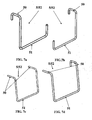
- the attachment means 40 (designed to cooperate with the tile 2) is constituted by a hook while the means 41 to make the attachment means 40 integral with the mounting profile 3 is constituted by a weld, a screw, crimping or other.
- the means 4 for fixing a tile 2 on a mounting profile 3 are constituted by a fixing member 42 comprising, on the one hand, at least one attachment means 40 designed to cooperate with the tile 2
- a fastening means 40 adopts, more particularly, the shape of a hook or the like, in particular obtained by deformation.
- this fastening member 42 comprises a means 41 for securing the attachment means 40 (and thus this fastening member 42 itself) of the mounting profile 3, more particularly of a wing 31 or (and preferably) a return 32 that includes this section 3.
- this means 41 to make integral may adopt the form of a female interlocking means (in particular constituted by a housing obtained by deformation) and able to cooperate with a male interlocking means (more particularly a wing 31 or a return 32) that comprises the mounting profile 3.
- such a fastener 42 may take the form of a clip (preferred embodiment), a clip, a hook or the like and / or may be obtained by deformation a blade (preferred embodiment), a tongue or the like, in particular metal.
- the means 5 for fixing a tile 2 on a mounting profile 3 are constituted by a fixing member 52 comprising, on the one hand, at least one attachment means 50 designed to cooperate with the tile 2
- a fastening means 50 adopts, more particularly, the shape of a hook or the like, in particular obtained by deformation.
- this fixing member 52 comprises a fastening means 51 designed to cooperate with the mounting profile 3, more particularly with the base 30 and / or with a wing 31 that includes such a mounting profile 3.
- such a fastening member 52 may take the form of a staple (preferred embodiment), a hook, a clip or the like and / or may be obtained by deformation of a thread (fashion preferred embodiment), a rod or the like, in particular metal.
- Such a fastener (42; 52) is deformable type, including elastically, this to allow its establishment on the tile 2 and on the mounting profile 3.
- the means for fixing a tile 2 on a mounting profile 3 may, again, be constituted by an adhesive or the like interposed between such a tile 2 and such a mounting profile 3.
- such glue comes, then, more particularly, to substitute for a fastener 52 as described above and as illustrated Figures 5 to 7 .
- the means for fixing a tile 2 on a mounting profile 3 are constituted by a screw, in particular a self-tapping screw, passing through the tile 2 (more particularly an opening that includes such a tile 2, in particular that comprise female interlocking means 100 of this tile 2 or means 9 for ensure the flow as described below) and cooperating with the mounting profile 3, in particular with a return 32 that includes this mounting profile 3.
- the covering device 1 comprises a plurality of tiles 2 which are intended to rest on at least one mounting profile 3.
- These tiles 2 comprise, then, each, at least one means 6 for receiving at least one such mounting profile 3.
- such a means 6 for receiving at least one mounting profile 3 comprises a housing 60, inside which is housed at least a portion of the mounting profile 3, more particularly a wing 31 or (and preferably) a return 32 that includes this mounting profile 3.
- This housing 60 extends over at least a part of the length of the tile 2, more particularly over the entire length of the tile 2.
- this housing 60 extends longitudinally and near a longitudinal edge 22 of the tile 2.
- this tile 2 which then comprises such a housing 60.
- such a housing 60 is constituted by a longitudinal groove 61 (continuous or interrupted by a recess 71 described below) extending over the entire length of the tile 2.
- Such a groove 61 is formed on the surface of the tile 2, more particularly on the surface of the lower face 21 of such a tile 2.
- a tile 2 (which includes the cover device 1 according to the invention) rests on two parallel mounting profiles 3.
- a tile 2 comprises, then, two means 6 for receiving such a mounting profile 3.
- Each of these means 6 extends over the entire length of the tile 2, this longitudinally and close to a longitudinal edge 22 of the tile 2.
- Each of these means 6 adopts the form of a housing 60, constituted by a longitudinal groove 61, and that comprises a longitudinal edge 23 of the tile 2.
- the covering device 1 comprises means (4; 5) for fixing a tile 2 on a mounting profile 3.
- These tiles 2 each comprise at least one means (7; 8) for receiving the means (4; 5) for fixing such a tile 2 on such a mounting profile 3.
- such means 7 for receiving the means 4 for fixing comprises a housing 70, inside which at least part of these means 4 are housed to fix, more particularly the fastening means 40 that these means 4 comprise for fixing.
- This housing 70 extends, again, on at least a part of the length of the tile 2. In addition, this housing 70 extends longitudinally and near a longitudinal edge 22 of the tile 2. There again, it is, more particularly, the longitudinal edge 23 of this tile 2 which comprises, then, such a housing 70.
- such a housing 70 is constituted by a recess 71 (in particular longitudinal) extending over a part of the length of the tile 2.
- Such a recess 71 is formed in depth in the tile 2 and / or extends in the extension (and at the rear) of the groove 61 that includes the means 6 for receiving at least one mounting profile 3.
- a tile 2 (which includes the cover device 1 according to the invention) rests on two mounting profiles 3.
- a tile 2 comprises at least two means 7 for receiving means 4 to fix such a tile 2 on these two mounting profiles 3.
- Each of these means 7 extends over a part of the length of the tile 2, this longitudinally and near a longitudinal edge 22 of the tile 2.
- Each of these means 7 adopts the form of a housing 70, constituted by a recess 71, and that comprises a longitudinal edge 23 of the tile 2.
- such a recess 71 has longitudinal walls, at least one of which comprises at least one additional attachment means designed to cooperate with at least one attachment means 40 that comprises the means 4 for fix a tile 2 on a mounting profile 3.
- Such additional attachment means adopts the shape of a hooking flange, a particular surface state of the longitudinal wall (rough, with unevenness or other) or the like.
- such means 8 for receiving the means 5 for fixing a tile 2 on a mounting profile 3 comprise a additional fastening means 80.
- such a complementary coupling means 80 is designed to cooperate with an attachment means 50 that comprise the means 5 for fixing.
- such a complementary attachment means 80 is constituted by a hooking flange or the like.
- the tile 2 which includes such complementary attachment means 80, this in the vicinity of a transverse edge 24 of the tile 2, more particularly near a transverse edge 24 rear (or upper).
- a transverse border 25 (more particularly the rear or upper transverse border, usually referred to as a bead) which comprises such complementary attachment means 80.
- this means 8 for receiving the means 5 for fixing also comprises a housing 81 inside which at least part of the means 5 for securing (more particularly the means for hanging 50). It is, more particularly, the means additional hooking 80 mentioned above which then comprises such a housing 81, this near a longitudinal edge 22 of the tile 2.
- the tile 2 (which comprises the covering device of the invention) comprises, near a transverse edge 24 and / or at a transverse edge 25, a means 9 designed to ensure the flow of water towards at least one longitudinal edge 22 of the tile 2.
- the tile 2 comprises such a means 9 to ensure the flow of water, this in the vicinity of the rear transverse edge 24 (or upper). It is, more particularly, the upper (or rear) transverse border of this tile 2 which then comprises such means 9.
- the longitudinal edge 22 of a tile 2 is positioned in line with the base 30 of the mounting profile 3.
- the water flows (through the means 9 to ensure its flow) towards a longitudinal edge 22 and, arrived at this longitudinal edge 22, flows inside the mounting profile 3 for its evacuation by this mounting profile 3.
- this means 9 (designed to ensure the flow of water towards at least one longitudinal edge 22 of the tile 2) extends transversely to the tile 2 and towards at least one longitudinal edge 22 of the tile 2.
- this means 9 for ensuring the flow of water extends between the two longitudinal edges 22 of the tile 2.
- such a means 9 for ensuring the flow of water towards a longitudinal edge 22 has a downward slope towards this longitudinal edge 22.
- the means 9 to ensure the flow of water is designed to ensure the flow of this water towards both edges longitudinal members 22 of the tile 2.
- this means 9 has a double downward slope each in the direction of such a longitudinal edge 22.
- Such means 9 to ensure the flow of water towards the two longitudinal edges 22 of the tile 2 takes the form of a groove, a gutter, a channel or the like.
- the tile 2 (more particularly, the upper or the rear transverse edge of this tile 2) which includes such means 9 to ensure the flow of water, this close to the edge transversal 24 upper (or rear).
- this means 9 can then be located downstream or below the upper face 20 of the tile 2.
- the tile 2 (more particularly, the transverse edge 25 below or before of this tile 2) also has a cover flange for extending over the means 9 to ensure the flow of water and that includes an adjacent tile 2 downstream.
- the covering device 1 comprises means (not shown) for fixing together two adjacent tiles 2, more particularly for immobilizing these two tiles 2 with respect to each other, this in a perpendicular direction to such a general plane in which these tiles extend 2.
- Such means for securing may then assume the shape of a pin or the like designed to cooperate, on the one hand, with the upper or the rear transverse edge (more particularly with the upper or rear transverse edge 24) of an adjacent downstream tile 2 and, on the other hand, with the lower or front transverse edge (more particularly with the lower or front transverse edge 24) of a tile 2 adjacent upstream.
- a characteristic of the tile 2 of the covering device 1 is that such a tile 2 comprises interlocking means 10, designed to cooperate with complementary interlocking means that comprises another adjacent tile 2, more particularly an upper tile 2 (located upstream) or a lower tile 2 (located downstream).
- interlocking means 10 advantageously makes it easier to assemble a new tile 2 with respect to an adjacent tile already implanted and / or to immobilize a tile 2 with respect to an adjacent tile, in particular according to a direction perpendicular to a general plane in which such a tile 2 extends.
- these interlocking means 10 are constituted, on the one hand, by a female interlocking means 100 that the tile 2 comprises in proximity to a transverse edge 24 and / or that comprises the transverse edge 25 of a such tile 2 and, secondly, by a male interlocking means 101 that includes the tile 2 near the other transverse edge 24 and / or that includes the other transverse edge 25 of the tile 2.
- the tile 2 which comprises the female interlocking means 100 near a transverse edge 24 rear (or upper) and / or the rear transverse border (or upper, usually called heel) of this tile 2 which comprises the female interlocking means 100.
- the male interlocking means 101 it is, more particularly, the tile 2 which comprises this male interlocking means 101 near a transverse edge 24 before (or lower) and / or the transverse edge 25 before ( or lower, usually called nose) of this tile 2 which comprises the male interlocking means 101.
- the male interlocking means 101 is constituted by a rib while the female interlocking means 100 is constituted by a groove which, moreover and advantageously, constitutes at least in part the means 9 for ensuring the flow of water towards the two longitudinal edges 22 of the tile 2.
- Another embodiment not forming part of the invention consists in that the female interlocking means 100 is constituted by a mortise while the male interlocking means 101 is constituted by a tenon.
- Yet another embodiment not forming part of the invention consists in that the female interlocking means 100 is constituted by a housing while the male interlocking means 101 is constituted by an elastic tongue, a rod, a finger or the like.
- the tile 2 comprises means for spacing the longitudinal edge 22 of two juxtaposed tiles 2 (more particularly the longitudinal edge 22 of a tile 2 with respect to the longitudinal edge 22 of another tile juxtaposed 2) and / or the transverse edge 24 of two adjacent tiles 2 (more particularly the transverse edge 24 of a tile 2 with respect to the transverse edge 24 of another adjacent tile 2, as the case may be, upper or lower).
- these means for spacing comprise, on the one hand, at least one member (more particularly, a pad, a finger, a pad or the like) fitted to a cover flange or a male interlocking means 101 (which includes an interlocking means 10 that the tile 2) comprises, and which extends in the direction of a means 9 to ensure the flow of the water 9 or a female interlocking means 100 (which comprises this means 10), this substantially perpendicular to the general plane of extension of the tile 2.
- a male interlocking means 101 which includes an interlocking means 10 that the tile 2 comprises, and which extends in the direction of a means 9 to ensure the flow of the water 9 or a female interlocking means 100 (which comprises this means 10), this substantially perpendicular to the general plane of extension of the tile 2.
- these means for spacing comprise a housing, equipping a means 9 to ensure the flow of water 9 or a female interlocking means 100 (which comprises a nesting means 10 that includes the tile 2) , arranged facing a member (more particularly in the bottom of the means 9 or the female interlocking means 100), and within which is housed such a member.
- these means for spacing equip such a tile 2 more particularly close to at least one longitudinal edge 22 of the tile 2.
- the tiles 2 (which comprises the covering device 1) comprise an upper face 20 and a lower face 21.
- such a tile 2 has an upper face 20 having at least one portion 200, or extending parallel to a general plane of extension of the tile 2, or having an inclination relative to this plane and extending, then and as the case, longitudinally or transversely to the tile 2.
- such an upper face 20 comprises a single portion 200 extending parallel to a general plane of extension of the tile 2.
- Such an embodiment advantageously allows, to position the upper face 20 of a tile 2 in the extension of the upper face 20 of an adjacent tile and a tile juxtaposed this for the realization of a roof having a flat surface and devoid of stairs (unlike the roofs of the state of the art).
- the upper face 20 may comprise at least one portion 200 having an inclination with respect to the general plane of extension of the tile 2.
- such a portion 200 may extend transversely ( figure 8 ) or longitudinal ( figure 9 ) relative to the tile 2.
- the upper face 20 of the tile 2 has a single portion 200 (corresponding to the entire surface of this upper face 20), having an inclination with respect to the general plane extension of the tile 2, and extending transversely relative to the tile 2.
- This embodiment advantageously makes it possible to make a roof with stairs.
- the upper face 20 of a tile 2 may comprise at least two portions 200, each having a different inclination slope or opposite.
- these portions 200 may extend longitudinally with respect to the tile 2, which advantageously makes it possible to facilitate the longitudinal flow. As visible on the figure 9 such a tile 2 may then have 5 portions 200 extending longitudinally.
- these portions 200 may extend transversely with respect to the tile 2. This advantageously makes it easier to take hold of an operator's foot (more particularly by creating an blocking point) and / or to reduce the speed of the water flow (particular application suitable for large crawlers) and / or to create a means for retaining the snow (in particular by conferring on such a portion 200 an inclination important compared to the plan of extension of the tile 2 and likely to constitute a means to retain the snow).
- such a tile 2 may then have 4 portions 200 which, two by two, have an inclination of opposite slope.
- the covering device 1 of the invention may also comprise means for at least limiting (or preventing) the longitudinal displacement, with respect to a mounting profile 3, of at least one tile 2 and / or means (4; 5) for fixing a tile 2 on a mounting profile 3.
- the means for at least limiting the longitudinal displacement of at least one tile 2 comprise, on the one hand, at least one lug, which comprises the mounting profile 3 (more particularly a wing 31 or, preferably, a return 32 of this mounting profile 3), and which extends laterally with respect to this mounting profile 3 (in particular with respect to a wing 31 or a return 32).
- a lug may be constituted by a deformation of a mounting profile portion 3 delimited by a cutout that comprises this mounting section 3.
- these means for at least limiting the longitudinal displacement of at least one tile 2 comprise at least one stopper, which cooperates with a pin as mentioned above, and that comprises the tile 2.
- a such stopper may be constituted by a housing, a transverse groove or the like.
- Another embodiment consists in that the means for at least limiting the displacement of a tile 2 relative to a mounting profile 3 are constituted by means for fixing such a tile 2 on such a mounting profile 3, plus particularly in the form of a screw as described above.
- the means for at least limiting the longitudinal displacement of the means 4 for fixing a tile 2 comprise, on the one hand, at least one cutout that comprises the mounting profile 3 (more particularly a wing 31 of this mounting profile 3) and, secondly, a finger, which cooperates with such a cutout, and that comprise the means 4 for fixing a tile 2 on such a mounting profile, more particularly that comprises a fixing member ( 42).
- the present invention thus also relates, and more particularly, to a roof covering tile 2 of a building intended to rest on a frame, in particular an tile 2 for a cover device 1 having the features described above.
- Such a tile 2 is preferably made of terracotta or the like.
- Such a tile 2 extends along a general plane of extension which, in the service position of this tile 2 (within the covering device 1), extends in the direction of the slope of the roof, and parallel to the plane roof as well as the plan of the frame.
- such a tile 2 comprises at least one means 6 for receiving a mounting profile 3 (and which has the characteristics described above) and at least one means (7; 8) for receiving means (4; 5). to fix this tile 2 on the mounting profile 3 (and which has the characteristics described above).
- This tile 2 comprises, again, a means 9 for ensuring the flow of water towards at least one such longitudinal edge 22 and having the characteristics described above.
- This tile 2 also comprises interlocking means 10, designed to cooperate with complementary interlocking means that comprises another adjacent tile 2.
- the tile 2 has an upper face 20 having at least one portion 200, or extending parallel to a general plane of extension of the tile 2, or having an inclination relative to this plane and s' extending, then and according to the case, longitudinally or transversely with respect to the tile 2.
Landscapes
- Engineering & Computer Science (AREA)
- Architecture (AREA)
- Civil Engineering (AREA)
- Structural Engineering (AREA)
- Mechanical Engineering (AREA)
- Roof Covering Using Slabs Or Stiff Sheets (AREA)
- Press-Shaping Or Shaping Using Conveyers (AREA)
- Finishing Walls (AREA)
Claims (15)
- Vorrichtung (1) zum Abdecken eines Gebäudes, dazu bestimmt, auf einem Tragwerk zu ruhen und umfassend, einerseits, zumindest ein Montageprofil (3), das dazu bestimmt ist, an dem Tragwerk befestigt zu werden, und, andererseits, eine Vielzahl von Dachziegeln (2), die dazu bestimmt sind, auf mindestens einem Montageprofil (3) zu ruhen und jeweils wenigstens ein Mittel (6) zur Aufnahme zumindest eines solchen Montageprofils (3) und zumindest ein Mittel (7; 8) zur Aufnahme der Mittel (4; 5) zum Befestigen eines Dachziegels (2) an einem solchen Montageprofil (3) umfassen, welche die besagte die Vorrichtung (1) umfasst, dadurch gekennzeichnet, dass der Dachziegel (2) Folgendes umfasst:- in der Nähe eines Querrandes (24) und/oder im Bereich eines Querrandes (25), ein Mittel (9), das sich quer zum Dachziegel (2) und zwischen den beiden Längsrändern (22) des Dachziegels (2) erstreckt und ausgelegt ist, um das Abfliessen von Wasser in Richtung auf diese zwei Längsränder (22) zu sichern;- Einsteckmittel (10), die geeignet sind, um mit ergänzenden Einsteckmitteln zusammenzuwirken, welche ein weiterer benachbarter Dachziegel (2) umfasst, und die einerseits aus einem männlichen Einsteckmittel (101), welchen der Dachziegel (2) in der Nähe eines Querrandes (24) umfaßt und/oder welchen ein Querrand (25) dieses Dachziegels (2) umfasst, und, andererseits, aus einem weiblichen Einsteckmittel (100), welchen der Dachziegel (2) in der Nähe eines anderen Querrandes (24) umfasst und/oder welchen ein andere Querrand (25) dieses Dachziegels (2) umfasst, bestehen, wobei dieses weibliche Einsteckmittel (100) aus einer Nut besteht, die zumindest teilweise das Mittel (9) zum Sichern des Abfliessen von Wasser in Richtung auf die zwei Längsränder (22) des Dachziegels (2) bildet.
- Vorrichtung (1) zum Abdecken nach Anspruch 1, dadurch gekennzeichnet, dass das Montageprofil (3) einerseits eine Basis (30), die dazu bestimmt ist, an dem Tragwerk befestigt zu werden, und, andererseits, mindestens einen Flügel (31) umfasst, der sich ab dieser Basis (30) in Längsrichtung relativ zu dieser Basis (30) erstreckt, während er mit dieser Basis (30) einen Winkel einschließt.
- Vorrichtung (1) zum Abdecken nach Anspruch 2, dadurch gekennzeichnet, dass das Montageprofil (3) ebenfalls zumindest einen Bogen (32) umfasst, der sich ab einem Flügel (31) in Längsrichtung relativ zu diesem Flügel (31) erstreckt, während er mit diesem Flügel (31) einen Winkel einschließt.
- Vorrichtung (1) zum Abdecken nach irgendeinem der vorhergehenden Ansprüche, dadurch gekennzeichnet, dass das Montageprofil (3) die Form einer Schiene, nälich aus Metall, annimmt, die eine Basis (30) sowie zwei Flügel (31), sogar zwei Bögen (32) umfasst.
- Vorrichtung (1) zum Abdecken nach irgendeinem der vorhergehenden Ansprüche, dadurch gekennzeichnet, dass die Mittel zum Befestigen eines Dachziegels (2) an ein Montageprofil (3) entweder aus einer Schraube, die den Dachziegel (2) durchsetzt und mit dem Montageprofil (3) zusammenwirkt, oder aus einem Klebstoff, der zwischen einem solchen Dachziegel (2) und einem solchen Montageprofil (3) angebracht ist, gebildet sind.
- Vorrichtung (1) zum Abdecken nach irgendeinem der Ansprüche 1 bis 4, dadurch gekennzeichnet, dass die Mittel (4; 5) zum Befestigen eines Dachziegels (2) an ein Montageprofil (3) wenigstens ein Einhakmittel (40; 50), das vorgesehen ist, um mit dem Dachziegel (2) zusammenzuwirken sowie je nach dem Fall ein Mittel (41), um dieses Einhakmittel (40) fest mit dem Montageprofil (3) zu verbinden, oder ein Einhakmittel (51), das vorgesehen ist, um mit dem Montageprofil (3) zusammenzuwirken, umfasst.
- Vorrichtung (1) zum Abdecken nach irgendeinem der vorhergehenden Ansprüche, dadurch gekennzeichnet, dass das Mittel (6) zum Aufnehmen von mindestens einem Montageprofil (3) und/oder das Mittel (7) zum Aufnehmen der Mittel zur Befestigung eines Dachziegels (2) an ein Montageprofil (3) eine Aussparung (60; 70) umfasst, in der mindestens ein Teil des Profils (3) oder zumindest ein Teil der Mittel (4) zum Befestigen untergebracht ist, die sich über zumindest einen Teil der Länge des Dachziegels (2) erstreckt, und zwar in Längsrichtung und in der Nähe eines Längsrandes (22) des Dachziegels (2).
- Vorrichtung (1) zum Abdecken nach irgendeinem der Ansprüche 1 bis 6, dadurch gekennzeichnet, dass das Mittel (8) zum Aufnehmen der Mittel (5) zur Befestigung eines Dachziegels (2) an ein Montageprofil (3) ein ergänzendes Einhakmittel (80), welches der Dachziegel (2) in der Nähe eines Querrandes (24) umfasst, umfassen.
- Vorrichtung (1) zum Abdecken nach irgendeinem der vorhergehenden Ansprüche, dadurch gekennzeichnet, dass die Vorrichtung (1) Mittel (11), um mindestens die Längsverschiebung, relativ zu einem Montageprofil (3), von mindestens eines Dachziegels (2) zu begrenzen, und/oder Mittel (4) zum Befestigen eines Dachziegels (2) an ein Montageprofil (3) umfasst.
- Dachziegel (2) einer Vorrichtung (1) zum Abdecken eines Gebäudes, die dazu bestimmt ist, auf einem Tragwerk zu ruhen, nämlich für eine Vorrichtung (1) zum Abdecken nach irgendeinem der vorhergehenden Ansprüche, wobei dieser Dachziegel (2), einerseits, zumindest ein Mittel (6) zum Aufnehmen eines Montageprofils (6) umfasst, welches eine Vorrichtung (1) zum Abdecken des Tragwerks umfasst, und das an dem Tragwerk befestigt ist, und andererseits Mittel (7; 8) zur Aufnahme der Mittel (4; 5) zum Befestigen dieses Dachziegels (2) an das Montageprofil (3) umfasst, welches eine Vorrichtung (1) zum Abdecken eines Tragwerks umfasst, dadurch gekennzeichnet, dass er Folgendes umfasst:- in der Nähe eines Querrandes (24) und/oder im Bereich eines Querrandes (25), ein Mittel (9), das sich quer zum Dachziegel (2) und zwischen den beiden Längsrändern (22) des Dachziegels (2) erstreckt und ausgelegt ist, um das Abfliessen von Wasser in Richtung auf diese zwei Längsränder (22) zu sichern;- Einsteckmittel (10), die geeignet sind, um mit ergänzenden Einsteckmitteln zusammenzuwirken, welche ein weiterer benachbarter Dachziegel (2) umfasst, und die einerseits aus einem männlichen Einsteckmittel (101), welchen der Dachziegel (2) in der Nähe eines Querrandes (24) umfaßt und/oder welchen ein Querrand (25) dieses Dachziegels (2) umfasst, und, andererseits, aus einem weiblichen Einsteckmittel (100), welchen der Dachziegel (2) in der Nähe eines anderen Querrandes (24) umfasst und/oder welchen ein andere Querrand (25) dieses Dachziegels (2) umfasst, bestehen, wobei dieses weibliche Einsteckmittel (100) aus einer Nut besteht, die zumindest teilweise das Mittel (9) zum Sichern des Abfliessen von Wasser in Richtung auf die zwei Längsränder (22) des Dachziegels (2) bildet.
- Dachziegel (2) nach Anspruch 10, dadurch gekennzeichnet, dass das Mittel (6) zur Aufnahme von mindestens einem Montageprofil (3) und/oder das Mittel (7) zur Aufnahme der Mittel (4) zur Befestigung des Dachziegels (2) an das Montageprofil (3) eine Aussparung (60; 70) umfasst, in der zumindest ein Teil des Montageprofils (3) oder zumindest ein Teil der Mittel zum Befestigen (4) untergebracht ist, welche sich über mindestens einen Teil der Länge des Dachziegels (2) erstreckt, und zwar in Längsrichtung und in der Nähe eines Längsrandes (22) des Dachziegels (2).
- Dachziegel (2) nach irgendeinem der Ansprüche 10 oder 11, dadurch gekennzeichnet, dass das Mittel (6) zur Aufnahme von mindestens einem Montageprofil (3) eine Aussparung (60) umfasst, die aus einer Längsnut (61) besteht, die sich über die gesamte Länge des Ziegels (2) erstreckt.
- Dachziegel (1) nach irgendeinem der Ansprüche 10 oder 11, dadurch gekennzeichnet, dass das Mittel (7) zur Aufnahme der Mittel (4) zur Befestigung eines Dachziegels (2) an ein Montageprofil (3) eine Aussparung (70) umfasst, die aus einer Ausnehmung (71) besteht, die sich über einen Teil der Länge des Ziegels (2) erstreckt.
- Dachziegel (2) nach Anspruch 10, dadurch gekennzeichnet, dass das Mittel (8) zur Aufnahme der Mittel (5) zur Befestigung eines Dachziegels (2) an ein Montageprofil (3) ein ergänzendes Einhakmittel (81) umfasst, welches der Dachziegel (2) in der Nähe eines Querrandes (24) umfasst und/oder welches ein Querrand (25) dieses Dachziegels (2) umfasst, und das vorgesehen ist, um mit einem Einhakmittel (50) zusammenzuwirken, welches die Mittel zum Befestigen (5) umfassen.
- Dachziegel (2) nach irgendeinem der Ansprüche 10 bis 14, dadurch gekennzeichnet, dass der Dachziegel (2) eine obere Fläche (20) umfasst, die zumindest einen Teil (200) umfasst, der sich parallel zu einer allgemeinen Ausstreckungsebene des Dachziegels (2) erstreckt oder die eine Neigung relativ zu dieser Ebene aufweist und sich je nach dem Fall in Längs- oder Querrichtung relativ zum Dachziegel (2) erstreckt.
Priority Applications (2)
| Application Number | Priority Date | Filing Date | Title |
|---|---|---|---|
| PL11306658T PL2474678T3 (pl) | 2011-01-07 | 2011-12-14 | Pokrycie dachowe i dachówka do pokrycia dachowego |
| HRP20151204TT HRP20151204T1 (hr) | 2011-01-07 | 2015-11-10 | Uređaj za prekrivanje krova zgrade i crijep uređaja za prekrivanje krova |
Applications Claiming Priority (1)
| Application Number | Priority Date | Filing Date | Title |
|---|---|---|---|
| FR1150136A FR2970275B1 (fr) | 2011-01-07 | 2011-01-07 | Dispositif d'habillage de rive de toit |
Publications (3)
| Publication Number | Publication Date |
|---|---|
| EP2474678A2 EP2474678A2 (de) | 2012-07-11 |
| EP2474678A3 EP2474678A3 (de) | 2012-12-26 |
| EP2474678B1 true EP2474678B1 (de) | 2015-08-19 |
Family
ID=45370450
Family Applications (2)
| Application Number | Title | Priority Date | Filing Date |
|---|---|---|---|
| EP11306656.7A Active EP2474680B1 (de) | 2011-01-07 | 2011-12-14 | Vorrichtung zum Verkleiden einer Dachkante, und Dachkantenelement |
| EP11306658.3A Active EP2474678B1 (de) | 2011-01-07 | 2011-12-14 | Vorrichtung zum Abdecken eines Gebäudes, und Dachziegel der Abdeckvorrichtung |
Family Applications Before (1)
| Application Number | Title | Priority Date | Filing Date |
|---|---|---|---|
| EP11306656.7A Active EP2474680B1 (de) | 2011-01-07 | 2011-12-14 | Vorrichtung zum Verkleiden einer Dachkante, und Dachkantenelement |
Country Status (9)
| Country | Link |
|---|---|
| EP (2) | EP2474680B1 (de) |
| DK (1) | DK2474678T3 (de) |
| ES (2) | ES2671906T3 (de) |
| FR (1) | FR2970275B1 (de) |
| HR (1) | HRP20151204T1 (de) |
| HU (2) | HUE028040T2 (de) |
| PL (2) | PL2474680T3 (de) |
| PT (1) | PT2474680T (de) |
| RS (1) | RS54373B1 (de) |
Families Citing this family (3)
| Publication number | Priority date | Publication date | Assignee | Title |
|---|---|---|---|---|
| DK201600044U3 (da) | 2016-04-01 | 2016-06-24 | Ditte Ørum Nielsen | arrangement til at fremme og beskytte blomster under vækst og flytning samt opbevaring |
| CN109750796A (zh) * | 2019-01-14 | 2019-05-14 | 中来智联能源工程有限公司 | 一种光伏瓦的安装结构及光伏系统 |
| CN109797913B (zh) * | 2019-01-14 | 2024-05-14 | 中来智联能源工程有限公司 | 一种用于光伏瓦系统安装的连接件及其安装结构 |
Citations (1)
| Publication number | Priority date | Publication date | Assignee | Title |
|---|---|---|---|---|
| JP2006291515A (ja) * | 2005-04-08 | 2006-10-26 | Miyazono Seisakusho:Kk | 屋根瓦 |
Family Cites Families (16)
| Publication number | Priority date | Publication date | Assignee | Title |
|---|---|---|---|---|
| FR364238A (fr) * | 1906-03-14 | 1906-08-17 | Louis Charles Henri Lemoine | Perfectionnements dans la fabrication des rives et faitières de toitures |
| US2984945A (en) * | 1958-04-02 | 1961-05-23 | Putnam Rolling Ladder Co Inc | Interlocking roof tiles |
| DE2338495A1 (de) * | 1973-07-30 | 1975-02-13 | Bosch & Wuestenrot Strukturbau | Dachabschluss am giebel und am dachfuss, insbesondere fuer satteldaecher |
| CH589765A5 (en) * | 1975-08-07 | 1977-07-15 | Stoecker & Co | Roof eave metal section - has aluminium alloy angled sections fixed together by screws and threaded holes with T-shaped clamp |
| DE2703989A1 (de) * | 1977-02-01 | 1978-08-03 | Aktual Bauteile & Umweltschutz | Dachkantenabdeckung |
| US4617770A (en) * | 1980-09-29 | 1986-10-21 | W. P. Hickman Co. | Nailerless roof edge, framing structure and building panel mounting assembly |
| WO1987004479A1 (en) * | 1986-01-23 | 1987-07-30 | Cange Controls Limited | Tiling |
| AT388590B (de) * | 1986-08-01 | 1989-07-25 | Sfs Stadler Ag | Dacheindeckung aus dachziegeln, dachsteinen u. dgl. |
| DE8816174U1 (de) * | 1988-12-30 | 1989-02-16 | Gugel, Fritz Gerhard, 7441 Grafenberg | Kastenartige Regenrinne für Dächer |
| GB2241520A (en) * | 1990-03-03 | 1991-09-04 | Cange Controls Ltd | Tiling |
| GB2298664B (en) * | 1993-12-10 | 1998-02-18 | Marley Building Materials Ltd | Roof tile system |
| FR2795757B1 (fr) * | 1999-06-29 | 2001-08-03 | Tuileries Huguenot Fenal | Tuile a rabat lateral |
| US20030051428A1 (en) * | 2001-09-14 | 2003-03-20 | Metal-Era, Inc. Waukesha, Wisconsin | Coping assembly having a stone and mortar appearance |
| US6845590B1 (en) * | 2002-05-10 | 2005-01-25 | Southern Aluminum Finishing Company, Inc. | Fascia systems for roof edges |
| AUPS297002A0 (en) * | 2002-06-14 | 2002-07-04 | Podirsky, Bernhard | Cladding apparatus method and system |
| US8196360B2 (en) * | 2006-01-12 | 2012-06-12 | Msr Innovations Inc. | Photovoltaic solar roof tile assembly system |
-
2011
- 2011-01-07 FR FR1150136A patent/FR2970275B1/fr not_active Expired - Fee Related
- 2011-12-14 EP EP11306656.7A patent/EP2474680B1/de active Active
- 2011-12-14 RS RS20150742A patent/RS54373B1/sr unknown
- 2011-12-14 HU HUE11306658A patent/HUE028040T2/en unknown
- 2011-12-14 PT PT113066567T patent/PT2474680T/pt unknown
- 2011-12-14 EP EP11306658.3A patent/EP2474678B1/de active Active
- 2011-12-14 ES ES11306656.7T patent/ES2671906T3/es active Active
- 2011-12-14 PL PL11306656T patent/PL2474680T3/pl unknown
- 2011-12-14 HU HUE11306656A patent/HUE038678T2/hu unknown
- 2011-12-14 DK DK11306658.3T patent/DK2474678T3/en active
- 2011-12-14 ES ES11306658.3T patent/ES2553257T3/es active Active
- 2011-12-14 PL PL11306658T patent/PL2474678T3/pl unknown
-
2015
- 2015-11-10 HR HRP20151204TT patent/HRP20151204T1/hr unknown
Patent Citations (1)
| Publication number | Priority date | Publication date | Assignee | Title |
|---|---|---|---|---|
| JP2006291515A (ja) * | 2005-04-08 | 2006-10-26 | Miyazono Seisakusho:Kk | 屋根瓦 |
Also Published As
| Publication number | Publication date |
|---|---|
| EP2474680B1 (de) | 2018-03-21 |
| HRP20151204T1 (hr) | 2016-01-01 |
| FR2970275B1 (fr) | 2015-02-27 |
| EP2474678A3 (de) | 2012-12-26 |
| ES2553257T3 (es) | 2015-12-07 |
| HUE038678T2 (hu) | 2018-11-28 |
| PL2474678T3 (pl) | 2016-01-29 |
| PT2474680T (pt) | 2018-06-14 |
| RS54373B1 (sr) | 2016-04-28 |
| DK2474678T3 (en) | 2015-11-23 |
| EP2474680A1 (de) | 2012-07-11 |
| HUE028040T2 (en) | 2016-11-28 |
| PL2474680T3 (pl) | 2018-08-31 |
| ES2671906T3 (es) | 2018-06-11 |
| EP2474678A2 (de) | 2012-07-11 |
| FR2970275A1 (fr) | 2012-07-13 |
Similar Documents
| Publication | Publication Date | Title |
|---|---|---|
| EP2195495B1 (de) | Vorrichtung zur befestigung von pv-modulen auf einem dach mit befestigungsmitteln für den durchlass eines luftstroms zwischen einer grundfläche und dem pv-modul | |
| EP1282753B1 (de) | Befestigungsvorrichtung für die längsränder von platten, latten oder wandverkleidungen mit kraftverteilung | |
| EP0497690B1 (de) | Abdeckvorrichtung | |
| FR2972471A1 (fr) | Revetement d'un pan de toiture muni de panneaux photovoltaiques lamines ou bi-verre standard | |
| EP2474678B1 (de) | Vorrichtung zum Abdecken eines Gebäudes, und Dachziegel der Abdeckvorrichtung | |
| FR2551120A1 (fr) | Toiture equipee d'une garniture de fermeture de l'espace sous le toit | |
| EP2211391B1 (de) | Anlage mit Photovoltaikmodulen | |
| EP0559292B1 (de) | Anschlusselement für Bauprofile und Konstruktionen, die mittels solcher Anschlusselemente verbundene Bauprofile enthalten | |
| EP0596818B1 (de) | Trauf-Dacheindeckungselement für ein Gebäudedach | |
| FR2516132A1 (fr) | Closoir universel de faitage de toiture | |
| FR3087969A1 (fr) | Structure support de modules rigides de couverture tels que des modules photovoltaïques et toiture la comportant | |
| EP0643192A1 (de) | Rolladenkasten | |
| WO2015186103A1 (fr) | Structure metallique pour un batiment et batiment, par exemple destine a l'elevage d'animaux, muni d'une telle structure | |
| FR2941986A1 (fr) | Panneau monobloc prefabrique pour la construction de mur | |
| EP1026359B1 (de) | Dichtung für Rolladenkasten | |
| EP1746217B1 (de) | Vorrichtung zum Verkleiden einer Treppe | |
| FR3099504A1 (fr) | Toiture-terrasse végétalisée, ventilée, sans acrotère, sur structure béton. | |
| FR2724409A1 (fr) | Ensemble de caisson de volet roulant, notamment pour des applications de rehabilitation | |
| FR3024881A1 (fr) | Element de doublis et couverture de batiment comprenant un tel element de doublis | |
| FR3035899A1 (fr) | Cheneau sabliere monobloc | |
| FR2981100A1 (fr) | Toiture pour abri leger, abri leger equipe d'une telle toiture et procede d'installation d'une telle toiture | |
| FR2521616A1 (fr) | Tuiles de sabliere ou gargouilles, toiture dont la ligne de sabliere est construite avec ces tuiles, et procede de pose de ces tuiles de sabliere | |
| FR2544000A1 (fr) | Procede de construction d'un bardage en petits elements, moyens en vue de la mise en oeuvre de ce procede et constructions ainsi realisees | |
| FR3142203A1 (fr) | Système d’habillage d’angle saillant d’une toiture métallique | |
| FR3097243A1 (fr) | Elément d’habillage pour tuiles |
Legal Events
| Date | Code | Title | Description |
|---|---|---|---|
| PUAI | Public reference made under article 153(3) epc to a published international application that has entered the european phase |
Free format text: ORIGINAL CODE: 0009012 |
|
| AK | Designated contracting states |
Kind code of ref document: A2 Designated state(s): AL AT BE BG CH CY CZ DE DK EE ES FI FR GB GR HR HU IE IS IT LI LT LU LV MC MK MT NL NO PL PT RO RS SE SI SK SM TR |
|
| AX | Request for extension of the european patent |
Extension state: BA ME |
|
| PUAL | Search report despatched |
Free format text: ORIGINAL CODE: 0009013 |
|
| AK | Designated contracting states |
Kind code of ref document: A3 Designated state(s): AL AT BE BG CH CY CZ DE DK EE ES FI FR GB GR HR HU IE IS IT LI LT LU LV MC MK MT NL NO PL PT RO RS SE SI SK SM TR |
|
| AX | Request for extension of the european patent |
Extension state: BA ME |
|
| RIC1 | Information provided on ipc code assigned before grant |
Ipc: E04D 1/34 20060101ALI20121116BHEP Ipc: E04D 12/00 20060101ALI20121116BHEP Ipc: E04D 1/12 20060101AFI20121116BHEP Ipc: E04D 1/02 20060101ALI20121116BHEP |
|
| 17P | Request for examination filed |
Effective date: 20130620 |
|
| RBV | Designated contracting states (corrected) |
Designated state(s): AL AT BE BG CH CY CZ DE DK EE ES FI FR GB GR HR HU IE IS IT LI LT LU LV MC MK MT NL NO PL PT RO RS SE SI SK SM TR |
|
| GRAP | Despatch of communication of intention to grant a patent |
Free format text: ORIGINAL CODE: EPIDOSNIGR1 |
|
| INTG | Intention to grant announced |
Effective date: 20150326 |
|
| GRAS | Grant fee paid |
Free format text: ORIGINAL CODE: EPIDOSNIGR3 |
|
| GRAA | (expected) grant |
Free format text: ORIGINAL CODE: 0009210 |
|
| AK | Designated contracting states |
Kind code of ref document: B1 Designated state(s): AL AT BE BG CH CY CZ DE DK EE ES FI FR GB GR HR HU IE IS IT LI LT LU LV MC MK MT NL NO PL PT RO RS SE SI SK SM TR |
|
| REG | Reference to a national code |
Ref country code: GB Ref legal event code: FG4D Free format text: NOT ENGLISH |
|
| REG | Reference to a national code |
Ref country code: CH Ref legal event code: EP |
|
| REG | Reference to a national code |
Ref country code: IE Ref legal event code: FG4D Free format text: LANGUAGE OF EP DOCUMENT: FRENCH |
|
| REG | Reference to a national code |
Ref country code: AT Ref legal event code: REF Ref document number: 743948 Country of ref document: AT Kind code of ref document: T Effective date: 20150915 |
|
| REG | Reference to a national code |
Ref country code: DE Ref legal event code: R096 Ref document number: 602011018888 Country of ref document: DE |
|
| REG | Reference to a national code |
Ref country code: HR Ref legal event code: TUEP Ref document number: P20151204 Country of ref document: HR |
|
| REG | Reference to a national code |
Ref country code: RO Ref legal event code: EPE |
|
| REG | Reference to a national code |
Ref country code: DK Ref legal event code: T3 Effective date: 20151116 |
|
| REG | Reference to a national code |
Ref country code: PT Ref legal event code: SC4A Free format text: AVAILABILITY OF NATIONAL TRANSLATION Effective date: 20151117 |
|
| REG | Reference to a national code |
Ref country code: ES Ref legal event code: FG2A Ref document number: 2553257 Country of ref document: ES Kind code of ref document: T3 Effective date: 20151207 |
|
| REG | Reference to a national code |
Ref country code: SE Ref legal event code: TRGR |
|
| REG | Reference to a national code |
Ref country code: FR Ref legal event code: PLFP Year of fee payment: 5 |
|
| REG | Reference to a national code |
Ref country code: HR Ref legal event code: T1PR Ref document number: P20151204 Country of ref document: HR |
|
| REG | Reference to a national code |
Ref country code: LT Ref legal event code: MG4D |
|
| REG | Reference to a national code |
Ref country code: NL Ref legal event code: FP |
|
| PG25 | Lapsed in a contracting state [announced via postgrant information from national office to epo] |
Ref country code: FI Free format text: LAPSE BECAUSE OF FAILURE TO SUBMIT A TRANSLATION OF THE DESCRIPTION OR TO PAY THE FEE WITHIN THE PRESCRIBED TIME-LIMIT Effective date: 20150819 Ref country code: LT Free format text: LAPSE BECAUSE OF FAILURE TO SUBMIT A TRANSLATION OF THE DESCRIPTION OR TO PAY THE FEE WITHIN THE PRESCRIBED TIME-LIMIT Effective date: 20150819 Ref country code: NO Free format text: LAPSE BECAUSE OF FAILURE TO SUBMIT A TRANSLATION OF THE DESCRIPTION OR TO PAY THE FEE WITHIN THE PRESCRIBED TIME-LIMIT Effective date: 20151119 Ref country code: LV Free format text: LAPSE BECAUSE OF FAILURE TO SUBMIT A TRANSLATION OF THE DESCRIPTION OR TO PAY THE FEE WITHIN THE PRESCRIBED TIME-LIMIT Effective date: 20150819 |
|
| PG25 | Lapsed in a contracting state [announced via postgrant information from national office to epo] |
Ref country code: IS Free format text: LAPSE BECAUSE OF FAILURE TO SUBMIT A TRANSLATION OF THE DESCRIPTION OR TO PAY THE FEE WITHIN THE PRESCRIBED TIME-LIMIT Effective date: 20151219 |
|
| PG25 | Lapsed in a contracting state [announced via postgrant information from national office to epo] |
Ref country code: EE Free format text: LAPSE BECAUSE OF FAILURE TO SUBMIT A TRANSLATION OF THE DESCRIPTION OR TO PAY THE FEE WITHIN THE PRESCRIBED TIME-LIMIT Effective date: 20150819 |
|
| REG | Reference to a national code |
Ref country code: DE Ref legal event code: R097 Ref document number: 602011018888 Country of ref document: DE |
|
| REG | Reference to a national code |
Ref country code: SK Ref legal event code: T3 Ref document number: E 20259 Country of ref document: SK |
|
| REG | Reference to a national code |
Ref country code: GR Ref legal event code: EP Ref document number: 20150402368 Country of ref document: GR Effective date: 20160201 |
|
| PLBE | No opposition filed within time limit |
Free format text: ORIGINAL CODE: 0009261 |
|
| STAA | Information on the status of an ep patent application or granted ep patent |
Free format text: STATUS: NO OPPOSITION FILED WITHIN TIME LIMIT |
|
| 26N | No opposition filed |
Effective date: 20160520 |
|
| PG25 | Lapsed in a contracting state [announced via postgrant information from national office to epo] |
Ref country code: SI Free format text: LAPSE BECAUSE OF FAILURE TO SUBMIT A TRANSLATION OF THE DESCRIPTION OR TO PAY THE FEE WITHIN THE PRESCRIBED TIME-LIMIT Effective date: 20150819 |
|
| REG | Reference to a national code |
Ref country code: HR Ref legal event code: ODRP Ref document number: P20151204 Country of ref document: HR Payment date: 20161125 Year of fee payment: 6 |
|
| REG | Reference to a national code |
Ref country code: HU Ref legal event code: AG4A Ref document number: E028040 Country of ref document: HU |
|
| REG | Reference to a national code |
Ref country code: FR Ref legal event code: PLFP Year of fee payment: 6 |
|
| PGFP | Annual fee paid to national office [announced via postgrant information from national office to epo] |
Ref country code: DK Payment date: 20161221 Year of fee payment: 6 Ref country code: CZ Payment date: 20161214 Year of fee payment: 6 Ref country code: MC Payment date: 20161214 Year of fee payment: 6 Ref country code: LU Payment date: 20161227 Year of fee payment: 6 Ref country code: SK Payment date: 20161214 Year of fee payment: 6 Ref country code: HU Payment date: 20161221 Year of fee payment: 6 |
|
| PGFP | Annual fee paid to national office [announced via postgrant information from national office to epo] |
Ref country code: RS Payment date: 20161124 Year of fee payment: 6 Ref country code: BG Payment date: 20161223 Year of fee payment: 6 Ref country code: HR Payment date: 20161125 Year of fee payment: 6 Ref country code: SE Payment date: 20161221 Year of fee payment: 6 |
|
| PG25 | Lapsed in a contracting state [announced via postgrant information from national office to epo] |
Ref country code: SM Free format text: LAPSE BECAUSE OF FAILURE TO SUBMIT A TRANSLATION OF THE DESCRIPTION OR TO PAY THE FEE WITHIN THE PRESCRIBED TIME-LIMIT Effective date: 20150819 |
|
| PG25 | Lapsed in a contracting state [announced via postgrant information from national office to epo] |
Ref country code: CY Free format text: LAPSE BECAUSE OF FAILURE TO SUBMIT A TRANSLATION OF THE DESCRIPTION OR TO PAY THE FEE WITHIN THE PRESCRIBED TIME-LIMIT Effective date: 20150819 |
|
| PG25 | Lapsed in a contracting state [announced via postgrant information from national office to epo] |
Ref country code: MT Free format text: LAPSE BECAUSE OF FAILURE TO SUBMIT A TRANSLATION OF THE DESCRIPTION OR TO PAY THE FEE WITHIN THE PRESCRIBED TIME-LIMIT Effective date: 20150819 Ref country code: TR Free format text: LAPSE BECAUSE OF FAILURE TO SUBMIT A TRANSLATION OF THE DESCRIPTION OR TO PAY THE FEE WITHIN THE PRESCRIBED TIME-LIMIT Effective date: 20150819 |
|
| REG | Reference to a national code |
Ref country code: FR Ref legal event code: PLFP Year of fee payment: 7 |
|
| REG | Reference to a national code |
Ref country code: AT Ref legal event code: UEP Ref document number: 743948 Country of ref document: AT Kind code of ref document: T Effective date: 20150819 |
|
| REG | Reference to a national code |
Ref country code: HR Ref legal event code: PBON Ref document number: P20151204 Country of ref document: HR Effective date: 20171214 |
|
| PG25 | Lapsed in a contracting state [announced via postgrant information from national office to epo] |
Ref country code: MK Free format text: LAPSE BECAUSE OF FAILURE TO SUBMIT A TRANSLATION OF THE DESCRIPTION OR TO PAY THE FEE WITHIN THE PRESCRIBED TIME-LIMIT Effective date: 20150819 |
|
| REG | Reference to a national code |
Ref country code: DK Ref legal event code: EBP Effective date: 20171231 |
|
| PG25 | Lapsed in a contracting state [announced via postgrant information from national office to epo] |
Ref country code: CZ Free format text: LAPSE BECAUSE OF NON-PAYMENT OF DUE FEES Effective date: 20171214 |
|
| PG25 | Lapsed in a contracting state [announced via postgrant information from national office to epo] |
Ref country code: RS Free format text: LAPSE BECAUSE OF NON-PAYMENT OF DUE FEES Effective date: 20180618 Ref country code: SE Free format text: LAPSE BECAUSE OF NON-PAYMENT OF DUE FEES Effective date: 20171215 |
|
| REG | Reference to a national code |
Ref country code: SK Ref legal event code: MM4A Ref document number: E 20259 Country of ref document: SK Effective date: 20171214 |
|
| PG25 | Lapsed in a contracting state [announced via postgrant information from national office to epo] |
Ref country code: LU Free format text: LAPSE BECAUSE OF NON-PAYMENT OF DUE FEES Effective date: 20171214 |
|
| PG25 | Lapsed in a contracting state [announced via postgrant information from national office to epo] |
Ref country code: HU Free format text: LAPSE BECAUSE OF NON-PAYMENT OF DUE FEES Effective date: 20171215 Ref country code: AL Free format text: LAPSE BECAUSE OF FAILURE TO SUBMIT A TRANSLATION OF THE DESCRIPTION OR TO PAY THE FEE WITHIN THE PRESCRIBED TIME-LIMIT Effective date: 20150819 |
|
| PG25 | Lapsed in a contracting state [announced via postgrant information from national office to epo] |
Ref country code: SK Free format text: LAPSE BECAUSE OF NON-PAYMENT OF DUE FEES Effective date: 20171214 Ref country code: HR Free format text: LAPSE BECAUSE OF NON-PAYMENT OF DUE FEES Effective date: 20171214 |
|
| PG25 | Lapsed in a contracting state [announced via postgrant information from national office to epo] |
Ref country code: BG Free format text: LAPSE BECAUSE OF NON-PAYMENT OF DUE FEES Effective date: 20180706 Ref country code: DK Free format text: LAPSE BECAUSE OF NON-PAYMENT OF DUE FEES Effective date: 20171231 |
|
| PG25 | Lapsed in a contracting state [announced via postgrant information from national office to epo] |
Ref country code: MC Free format text: LAPSE BECAUSE OF NON-PAYMENT OF DUE FEES Effective date: 20180102 |
|
| PGFP | Annual fee paid to national office [announced via postgrant information from national office to epo] |
Ref country code: PT Payment date: 20251120 Year of fee payment: 15 |
|
| PGFP | Annual fee paid to national office [announced via postgrant information from national office to epo] |
Ref country code: NL Payment date: 20251127 Year of fee payment: 15 |
|
| REG | Reference to a national code |
Ref country code: CH Ref legal event code: U11 Free format text: ST27 STATUS EVENT CODE: U-0-0-U10-U11 (AS PROVIDED BY THE NATIONAL OFFICE) Effective date: 20260101 |
|
| PGFP | Annual fee paid to national office [announced via postgrant information from national office to epo] |
Ref country code: GB Payment date: 20251229 Year of fee payment: 15 |
|
| PGFP | Annual fee paid to national office [announced via postgrant information from national office to epo] |
Ref country code: AT Payment date: 20251124 Year of fee payment: 15 |
|
| PGFP | Annual fee paid to national office [announced via postgrant information from national office to epo] |
Ref country code: IT Payment date: 20251209 Year of fee payment: 15 |
|
| PGFP | Annual fee paid to national office [announced via postgrant information from national office to epo] |
Ref country code: FR Payment date: 20251016 Year of fee payment: 15 |
|
| PGFP | Annual fee paid to national office [announced via postgrant information from national office to epo] |
Ref country code: BE Payment date: 20251226 Year of fee payment: 15 Ref country code: GR Payment date: 20251124 Year of fee payment: 15 |
|
| PGFP | Annual fee paid to national office [announced via postgrant information from national office to epo] |
Ref country code: IE Payment date: 20251126 Year of fee payment: 15 |
|
| PGFP | Annual fee paid to national office [announced via postgrant information from national office to epo] |
Ref country code: PL Payment date: 20251120 Year of fee payment: 15 |
|
| PGFP | Annual fee paid to national office [announced via postgrant information from national office to epo] |
Ref country code: RO Payment date: 20251127 Year of fee payment: 15 |
|
| PGFP | Annual fee paid to national office [announced via postgrant information from national office to epo] |
Ref country code: ES Payment date: 20260112 Year of fee payment: 15 |
|
| PGFP | Annual fee paid to national office [announced via postgrant information from national office to epo] |
Ref country code: DE Payment date: 20251231 Year of fee payment: 15 |
|
| PGFP | Annual fee paid to national office [announced via postgrant information from national office to epo] |
Ref country code: CH Payment date: 20260101 Year of fee payment: 15 |