EP2476823A2 - Poignée d'actionnement - Google Patents
Poignée d'actionnement Download PDFInfo
- Publication number
- EP2476823A2 EP2476823A2 EP20110189456 EP11189456A EP2476823A2 EP 2476823 A2 EP2476823 A2 EP 2476823A2 EP 20110189456 EP20110189456 EP 20110189456 EP 11189456 A EP11189456 A EP 11189456A EP 2476823 A2 EP2476823 A2 EP 2476823A2
- Authority
- EP
- European Patent Office
- Prior art keywords
- handle
- receptacle
- neck
- stop
- window
- Prior art date
- Legal status (The legal status is an assumption and is not a legal conclusion. Google has not performed a legal analysis and makes no representation as to the accuracy of the status listed.)
- Withdrawn
Links
Images


Classifications
-
- E—FIXED CONSTRUCTIONS
- E05—LOCKS; KEYS; WINDOW OR DOOR FITTINGS; SAFES
- E05B—LOCKS; ACCESSORIES THEREFOR; HANDCUFFS
- E05B15/00—Other details of locks; Parts for engagement by bolts of fastening devices
- E05B15/0053—Other details of locks; Parts for engagement by bolts of fastening devices means providing a stable, i.e. indexed, position of lock parts
- E05B15/006—Spring-biased ball or roller entering a notch
-
- E—FIXED CONSTRUCTIONS
- E05—LOCKS; KEYS; WINDOW OR DOOR FITTINGS; SAFES
- E05B—LOCKS; ACCESSORIES THEREFOR; HANDCUFFS
- E05B13/00—Devices preventing the key or the handle or both from being used
- E05B13/10—Devices preventing the key or the handle or both from being used formed by a lock arranged in the handle
- E05B13/106—Devices preventing the key or the handle or both from being used formed by a lock arranged in the handle for handles pivoted about an axis perpendicular to the wing
-
- E—FIXED CONSTRUCTIONS
- E05—LOCKS; KEYS; WINDOW OR DOOR FITTINGS; SAFES
- E05B—LOCKS; ACCESSORIES THEREFOR; HANDCUFFS
- E05B15/00—Other details of locks; Parts for engagement by bolts of fastening devices
- E05B15/0053—Other details of locks; Parts for engagement by bolts of fastening devices means providing a stable, i.e. indexed, position of lock parts
-
- E—FIXED CONSTRUCTIONS
- E05—LOCKS; KEYS; WINDOW OR DOOR FITTINGS; SAFES
- E05B—LOCKS; ACCESSORIES THEREFOR; HANDCUFFS
- E05B3/00—Fastening knobs or handles to lock or latch parts
-
- E—FIXED CONSTRUCTIONS
- E05—LOCKS; KEYS; WINDOW OR DOOR FITTINGS; SAFES
- E05B—LOCKS; ACCESSORIES THEREFOR; HANDCUFFS
- E05B3/00—Fastening knobs or handles to lock or latch parts
- E05B3/08—Fastening the spindle to the follower
-
- E—FIXED CONSTRUCTIONS
- E05—LOCKS; KEYS; WINDOW OR DOOR FITTINGS; SAFES
- E05B—LOCKS; ACCESSORIES THEREFOR; HANDCUFFS
- E05B15/00—Other details of locks; Parts for engagement by bolts of fastening devices
- E05B15/02—Striking-plates; Keepers; Bolt staples; Escutcheons
-
- E—FIXED CONSTRUCTIONS
- E05—LOCKS; KEYS; WINDOW OR DOOR FITTINGS; SAFES
- E05B—LOCKS; ACCESSORIES THEREFOR; HANDCUFFS
- E05B15/00—Other details of locks; Parts for engagement by bolts of fastening devices
- E05B15/04—Spring arrangements in locks
- E05B2015/0462—Ring springs
Definitions
- the invention relates to an actuating handle for a window or a door according to the preamble of claim 1.
- Actuation handles for windows and doors are well known. They usually have a stopper body which can be fixed to a window or door leaf, and a handle which is axially fixed rotatably mounted in the stop body and the opening or closing of the window or the door via a driver - usually a square pin - with an actuating element in the window frame or in the lock case is in operative connection, for example, with a gearbox or a locknut.
- latching means are provided between the handle and the stopper body, which upon reaching a defined angular position (functional position) of the handle relative to the stopper body in such a way engage each other that the torque required to rotate the handle in such an excellent angular position or position is greater than the torque required for turning outside the respective functional position.
- the latter are thus clearly noticeable to the user.
- the latching means are usually circumferentially formed in a handle neck attaching to the handle or in a rotatably connected latching disc and in the stopper body. These are usually locking lugs, latching projections, locking balls o.
- DE 33 20 192 C2 used in a door fitting as locking means axially rising wedge sections which are frontally formed on a axially, but rotatably mounted against a spring in the handle neck sleeve.
- the wedge sections engage in complementary wedge sections of a guide collar, which is fixed by means of a screw in the stopper body.
- DE 42 27 973 C3 discloses a window or door fitting with a handle which is rotatably mounted with a neck bearing part in a bearing sleeve and which engages with an actuating shaft approach (square pin) in a closure actuating element which is rotatably mounted in a fitting housing mounted in a Falzaus strictlyung.
- the neck bearing part consists of a collar sleeve which is axially displaceably mounted on the actuating shaft projection and which is acted on by a helical spring surrounding the actuating shaft shoulder and supported in the grip neck of the handle.
- the rotatably mounted on the square pin collar sleeve and the rotatably fixed in the door leaf bearing sleeve are formed as axially acting latching parts, wherein the collar sleeve and the bearing sleeve are provided at their mutually facing end faces with locking means, preferably with trapezoidal in the Queh Eckharder bain radial ribs in the corresponding Engage radial grooves.
- the axial fixing of the handle takes place with the aid of a securing shaft arranged on the securing member, which engages in a corresponding recess in the closure actuating element.
- actuating handles or fittings have the disadvantage that sometimes complicated special components are necessary, which are usually expensive and expensive to manufacture.
- installation of actuation handles on standard window profiles or standard doors is not possible because the specified in defined dimensions Boreholes or recesses can not be used. Therefore, special solutions are always necessary, which precludes a broad and cost-effective application.
- special tools are required for the disassembly of the operating handle, which must be inserted laterally into an engagement opening in the transmission in order to operate the securing member of the square pin can. Such openings are not provided in standard gearboxes and standard window profiles.
- the aim of the invention is to overcome these and other disadvantages of the prior art and to provide an actuating handle, which is constructed inexpensively by simple means and which can be mounted on standard or standard doors.
- the actuating handle should also be economically producible and have a permanently high stability and reliability in use.
- the invention provides that at least a first locking means is disposed on a stop body facing the end face of the handle neck, and that the stop body concentric with the axis of rotation of the handle has a receptacle, in which at least one second latching means is mounted displaceably parallel to the axis of rotation, wherein the second latching means is acted upon in the direction of the handle neck with a spring force and can be brought into engagement with the at least one first latching means.
- an axially displaceable mounted in the receptacle of the stopper locking means allows the use of an axially and rotatably connected to the handle handle neck, which forms a stable receptacle for the driver and ensures a stable as well as permanently reliable storage of the handle in the stop body.
- the actuating handle has clearly defined by the formed in the stop body facing the end face of the handle neck first detent means and by the second detent means guided in the recording and always for the user noticeable locking positions, so that the individual functional positions of the handle are detected quickly and accurately, which facilitates the handling of the window or the door.
- the handle thus uses a locking mating between an axially fixed rotatable locking means in the handle and a rotatably axially displaceable latching means in the stop body, the latter being mounted parallel to the axis of rotation of the handle in the receptacle of the stopper body slidably.
- the spring force ensures that the second locking means permanently acted upon in the direction of the handle neck with a spring force and with the at least one first locking means upon reaching the functional positions can be brought into engagement.
- the entire handle can be manufactured inexpensively by simple means. Due to the selectable geometries and dimensions, it can also be mounted at any time on standard or standard doors.
- the second locking means is formed in a preferred embodiment of a slider, which is mounted axially displaceable and rotationally fixed in the receptacle of the stop body along the axis of rotation, wherein between the slider and a bottom of the receptacle of the stopper body, a spring or a spring assembly is arranged.
- the slider may be formed, for example, as a ring which slides coaxially on the actuating element and which rotatably receives the driver.
- the spring may be formed as a simple coil spring or a plate spring, which further has a favorable effect on the production and assembly costs.
- a further embodiment provides that the stopper body has a stop plate which comes to rest on the window or the door, wherein the stop plate is provided on its rear side facing the window or the door with cams.
- the latter form an anti-rotation device for the stop plate on the door or the window, so that the actuating handle is always reliably held in position with its stopper body.
- the stop plate and the cams are provided with through holes for receiving fastening screws.
- An alternative provides that not the stop plate is axially bolted to the window or door, but that the driver of the handle is anchored axially in the actuator of the window or the door. In this way, the through holes in the stop plate can be omitted and the latter can be used immediately as a decorative Element to be used. An additional cap for the screws is no longer necessary.
- a variant of the actuating handle according to the invention provides that the receptacle of the stopper body is formed within the stop plate.
- the latter can therefore continue to be designed in their dimensions and in their design as an ordinary rosette, which is versatile.
- the receptacle of the stopper body is arranged below the stop plate. This makes it possible to reduce the stop plate on a thin plate which rests flat on the window or door and only requires a minimum height. The visible to the outside part of the rosette of the door or window handle is thus reduced to a minimum, which opens up completely new and aesthetically pleasing design options of actuating handle. At the same time it is possible to make the below the stop plate recording so that it can be sunk in the usual standard windows and standard doors central bore on the actuator in the window frame or in the lock case.
- the actuating handle can also be mounted in this embodiment at any time on standard doors or standard windows, for example, when conventional actuation handles or fittings should be replaced by inventive handle with a new design.
- the cost is conceivably low because neither the windows and doors replaced nor additional or other holes must be introduced into the window or door sash.
- the invention provides that in the receptacle of the stopper body, a sleeve is inserted against rotation, which receives the handle neck of the handle and the slider, wherein the handle neck is rotatable and the sliding body axially displaceable and non-rotatably mounted in the sleeve.
- the latter thus forms for the handle a stable pivot bearing and at the same time a kind of linear guide for the slider, so that this and the handle neck with its locking means the front side can always be reliably engaged.
- the existing example of a plastic sleeve can be manufactured inexpensively and mounted as quickly as convenient.
- the latching means are expediently corresponding latching recesses and latching projections, which are each integral with the handle neck and / or the slider, which is further has a favorable effect on the production costs. But you can also form the locking means separately and connect to the handle neck or the slider.
- the handle neck is a separate component and the front side inserted into the handle and fixed therein.
- the handle can be designed individually and provided in the manner of a modular system according to the customer with a handle bearing the locking means. This takes the driver against rotation and fixes it axially, so that the handle, the handle neck and the driver form a preassembled unit. This can also be used - depending on the purpose - as a door or window handle, which has a favorable effect on warehousing and logistics.
- the handle neck can also be designed such that the insertion of the driver is effected in a first direction and locked in the opposite direction.
- the handle neck forms a kind of Klemmgesperre, which sets the driver axially after insertion into the handle neck without the use of tools in a certain length or position.
- variable lengths of the driver can be realized and adjust the actuating handle quickly and easily to different window or door thicknesses.
- EP 1 683 933 A1 The applicant discloses the content of which is hereby incorporated by reference
- the driver is axially and rotatably fixed relative to the stopper body, preferably in the actuator in the window frame or in the lock case, namely in the gearbox or in the locknut.
- the free end of the driver is for this purpose provided with a suitable locking or locking element, which is releasably anchored in or behind the actuator. In this way it is possible to mount the entire actuating handle without any tools on the window or on the door.
- the visible part of the stopper body is reduced to a minimum, because the provided between the handle and the stopper locking device with their locking means under the Stop plate and therefore lies in the window or door leaf. Visible is therefore only the stop plate of the stopper body, which can be reduced to a simple flat disc or a simple flat plate with a small thickness.
- a further embodiment of the invention provides that in the handle a lock cylinder is provided with a closing element, wherein the handle with the aid of the closing element with respect to the stopper body is lockable.
- the arrangement of the locking device, in particular of the axially displaceable locking means, in a receptacle in the stop body, the handle offers a variety of ways to accommodate a lock cylinder without the handle must take bulky or greatly enlarged dimensions.
- the handle can therefore - as well as the stop plate - are made extremely slim and delicate while maintaining reliable stability and safety.
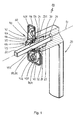
- actuating handle is designed as a window fitting. It serves to open, close or tilt a window (not shown) equipped with a tilt-and-turn fitting.
- a (also not shown) Drehkipp mechanism is integrated within the window or within the window sash, which can be actuated via the actuating handle 10.
- the latter has - as well as the Fig. 2 and 3 show - a handle 20 which is rotatably mounted with a handle neck 21 about a rotational axis D in a Anfordköper 40 and about a driver 30, preferably a square pin, with a rotatable in the window sash mounted (not shown) actuator of the tilt and turn mechanism is in operative connection.
- the actuating element of the tilt-turn mechanism is preferably a gearbox, which is provided centrally with a square recess which receives the free end 32 of the square pin 30 in a form-fitting manner.
- the handle neck 21 is formed opposite the handle 20 as a separate component 23 which is inserted into the handle 20 at the front side. This is provided for this purpose with a corresponding recess 24 whose depth is dimensioned such that the end formed by the component 23 handle neck 21 protrudes as a pivot pin from the handle 20.
- a square recess 231 is centrally introduced to the rotation axis D, which receives the driver or the square pin 30 against rotation.
- the axial location of the square pin 30 in the handle neck 21 or in the component 23 and its fixing in the handle 20 is preferably carried out by pressing the components 20, 23, 30, wherein first the square pin 30 with its end 31 in the square recess 231 of the component 23 and then the component 23 is pressed with the square pin 30 into the recess 24 of the handle 20.
- beads or grooves 232 are preferably introduced on the outer circumference of the component 23.
- the parts 20, 23, 30 can be caulked. If required, an additional anti-rotation device can also be provided.
- the handle 20 forms together with the handle neck 21 and the square pin 30 a preassembled unit.
- the square pin 30, the component 23 and the handle 20 can also connect the square pin 30, the component 23 and the handle 20 cohesively, for example by gluing or welding.
- the component 23 may be formed integrally with the handle 20.
- the component 23 or the handle neck 21 is designed such that the insertion of the square pin 30 in a first direction R1 can be effected and locked in the opposite direction R2.
- the component 23 has in the interior a locking or clamping element (not shown) which can be frictionally, forcefully and / or frictionally engaged with the square pin 30, wherein the blocking or locking elements acted upon in the direction R2 by a permanent force Clamping elements of the moved in the direction of R1 square pin 30 are axially and / or radially actuated while they fix the moved in the direction R2 square pin 30 directly.
- a locking or clamping element (not shown) which can be frictionally, forcefully and / or frictionally engaged with the square pin 30, wherein the blocking or locking elements acted upon in the direction R2 by a permanent force Clamping elements of the moved in the direction of R1 square pin 30 are axially and / or radially actuated while they fix the moved in the direction R2 square pin 30 directly.
- Fig. 4 shows the handle neck 21 carries on its the stopper body 40 facing end face 22 first latching means 52 which are formed in the form of locking recesses 531, 532.
- first latching means 52 which are formed in the form of locking recesses 531, 532.
- a total of eight latching recesses 531, 532 are introduced into the end face 22, which are arranged radially with respect to the axis of rotation D, with four longer latching recesses 531 extend from the peripheral edge of the handle neck 21 to or until just before the square recess 231, while four Further locking recesses 532 are formed shorter in the radial direction.
- the longer locking recesses 531 are arranged at an angular distance of 90 ° and formed substantially niksegment- or trapezoidal.
- the shorter locking recesses 532 are offset by 45 ° also at an angular distance of 90 ° to each other and are substantially niksegment- or trapezoidal to straight.
- the angular distance between the alternating recesses 531, 532 is therefore 45 °.
- the fixing of the actuating handle 10 on the window sash via the stopper body 40 which is essentially formed by a relatively thin and flat stop plate 42, which comes flat on the window sash to the plant and which is provided on its side facing the window sash 43 with two cams 431 ,
- the latter engage in two in the window sash introduced (not shown) cam holes, which are arranged symmetrically to both sides of a (also not shown) central bore in the window sash.
- the distances and dimensions of the central bore and the cam bores preferably correspond to standardized specifications and are prefabricated in numerous windows as standard, so that the window fitting 10 can be mounted directly on a variety of standard windows.
- Both the stopper plate 42 and the projections 431 are provided with through holes 432. These are used to hold mounting screws (not shown), which are either screwed into the window sash or into a housing of the Tilt & Turn mechanism. The latter can be provided with threaded holes for this purpose.
- a receptacle 44 is formed on the rear side 43 concentric with the axis of rotation D of the handle 20. This has adjacent to an opening 46 in the front 41 of the stop plate 42 has a cylindrical wall 47 and a bottom 45 which is centrally provided with a through hole 451.
- the inner diameter of the wall 47 corresponds to the diameter of the opening 46 in the stop plate 42, while the diameter of the through hole 451 in the bottom 45 of the receptacle 44 for the rotatable mounting of the square pin 30 is smaller is.
- the outer diameter of the cylindrical wall 47 is selected such that the receptacle 44 can be sunk when placing the stopper body 40 on the window sash in the central bore between the cam holes, so that the stop plate 42 always rests flat on the window sash and to the outside a minimum height having.
- the receptacle 44 lies below the stop plate 42 and is generally cup-shaped or pot-shaped. It serves to receive at least one second locking means 54 which is mounted displaceably within the receptacle 44 parallel to the axis of rotation D and in excellent functional positions of the handle 20 with the at least one first locking means 53 is engageable.
- the second locking means 54 for example, a detent ball, a locking cam or a locking projection - acted upon in the direction of the handle neck 21 with a spring force.
- a plurality of second locking means 54 are formed together on a sliding body 60 which is mounted axially displaceable and rotationally secured in the receptacle 44 of the stopper body 40 along the axis of rotation D.
- the slider 60 is formed as a ring 61 which has a central through hole 62 for the square pin 30 and at its (unspecified) peripheral edge at angular intervals of 90 ° preferably four guide cam 64 carries, which extend parallel to the axis of rotation D.
- end face 63 of the ring 61 On its side facing the handle 20 end face 63 of the ring 61 carries the second locking means 54, which are formed corresponding to the recesses 531, 532 in the end face 22 of the handle neck 21 as latching projections 551, 552.
- a total of eight locking projections 551, 552 are provided, which are integral with the end face 63.
- Each latching projection 551, 552 is arranged radially with respect to the axis of rotation D, with four longer latching projections 551 extending from the peripheral edge of the ring 61 to the passage opening 61, while four further latching projections 552 are shorter in the radial direction.
- the longer latching projections 551 are arranged at an angular distance of 90 ° and formed substantially Vietnamese niksegment- or trapezoidal.
- the shorter latching projections 552 are offset by 45 ° also at an angular distance of 90 ° to each other. They are essentially niksegment- or funnel-shaped until straight. The angular distance between the alternating locking projections 551, 552 is therefore 45 °.
- a sleeve 70 which is inserted from above into the opening 46 of the stopper body 40. It has a cylindrical wall 71 in which four longitudinal grooves 74 are introduced parallel to the axis of rotation D and at angular intervals of 90 °. These take on the guide cam 64 of the slider 60 and the ring 61, so that it is mounted axially displaceably and non-rotatably within the sleeve 70 along the axis of rotation D.
- the longitudinal grooves 74 are formed in the sleeve 70 open on one side, so that the wall 71 is divided into individual wall sections 72. These bear at their ends facing the window wing longitudinal pin 75, which engage in corresponding axial openings 48 in the bottom 45 of the receptacle 44, so that the sleeve 70 is rotatably locked in the receptacle 44.
- the axial length of the cylindrical wall 71 is dimensioned such that the sleeve 70 protrudes with a portion 76 on the front side 41 of the stop plate 42.
- the portion 76 forms the pivot bearing for the handle neck 21 of the handle 20, wherein the outer diameter of the handle neck 21 corresponds to the inner diameter of the sleeve 70 and the portion 76, so that the handle 20 with little play always stable and reliable in the sleeve 70 and thus is rotatably mounted in the stopper body 40.
- a spring assembly 80 is arranged, which is formed by a plurality, preferably four disc springs 81. These enclose the square pin 30 and press the slider 60 and thus the ring 61 and the locking projections 551, 552 with a defined spring force in the direction of the handle neck 21, so that the locking projections 551, 552 in excellent functional positions of the handle 20 with the axial locking recesses 531, 532 of the handle neck 21 engage.
- the latching means 52, 54 thus form a latching device which, due to the axially formed latching contours, is non-positively and / or positively engaged with one another in at least one functional position of the handle 20.
- the finding of the functional positions of the actuating handle 10 is facilitated, because the torque required to rotate the handle 20 in an excellent functional position is greater than that for rotating due to the spring force generated by the spring assembly 80 Required torque outside the respective functional position.
- the formation of the eight locking recesses 531, 532 and the corresponding locking projections 551, 552 also ensures that in the excellent angular positions of the handle 20 at intervals of 90 °, a precise locking takes place, in which positions all eight projections 551, 552 in the engage corresponding recesses 531, 532. Nevertheless, only four locking positions are present, because the large locking projections 551 can not engage in the small locking recesses 532 after 45 ° rotation. This succeeds only after a rotation of 90 °. As a result of this doubling of the latching pairings, the latching device is extremely wear-resistant and the handle 20 is always precisely and reliably locked in the excellent rotary or functional positions.
- Each clamping disc 90, 91 has in known manner at its inner periphery with respect to the axis of rotation D obliquely employed spring tongues 92, which engage with the (unspecified) outer surfaces of the square pin 30 into engagement.
- a cover 94 is arranged over the stopper plate 42 in a manner known per se. Between this and the handle 20, an annular spring 95 is arranged, which presses the cover 94 against the stop plate 42.
- the cover 94 may additionally or alternatively also be locked to the stop plate 42.
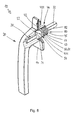
- Fig. 6 shows a lockable embodiment of the actuating handle 10.
- a lock cylinder 96 is inserted into the handle 20, which can engage in a corresponding functional position of the handle 20 relative to the stopper body 40 with a locking pin 97 in the stop plate 42.
- the latter is - as well as the cover 94 - provided with a bore 49 which receives the locking pin 97 in the locked position of the lock cylinder 96 with little movement play.
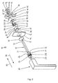
- FIG. 7 Also in the embodiment of Fig. 7 like reference characters designate like components.
- This embodiment dispenses with a screw connection of the stopper body 40 with the casement or the door leaf. Accordingly, the stopper plate 42 is formed without through holes 432. On the back 13 of the stop plate 42 are only two (not visible here) projections 431, which engage in anti-rotation in cam holes of the window sash.
- the second locking means 54 On the end face 63 of the ring 61 sit the second locking means 54, wherein in this embodiment, only four locking projections 551 are provided at intervals of 90 °. Accordingly, only four locking recesses 531 are introduced in the end face 22 of the handle neck 21, which are also arranged at intervals of 90 °.
- the spring 80 between the slider 60 and the bottom 45 of the receptacle 44 is formed as a helical spring 82 which surrounds the square pin 30. It is supported on the bottom 45 and presses the ring 61 with the axial Ratsvorsprüngen 551 in the excellent locking positions of the handle frictionally in the associated also axially formed locking recesses 531 in the handle neck 21 of the handle 20. This is rotatably mounted in the stopper body 40, wherein in the opening 46 of the receptacle 44 a sliding ring 78 is inserted, which may be made of plastic, for example.
- a cover 94 may be arranged to, for example, the actuating handle in a certain manner to make a visual impression.
- the cover 94 is not necessary because the stop plate 42 already has a closed surface.
- the cover 94 is also provided here with a central recess 941. It is suitably below the sliding ring 78, ie this engages with a neck portion 79 through the recess 941 through into the opening 46, so that the handle neck 21 of the handle 20 is stable and precisely stored in the stopper body 40.
- Fig. 8 also dispenses with fastening screws and the sleeve 70.
- the ring 61 of the slider 60 is guided by means of guide cam 64 in corresponding longitudinal slots 471 of the wall 47.
- a helical spring 80 which surrounds the square pin 30, is supported on the bottom 45 of the receptacle 44 and pushes the slider with the locking means 54 in the direction of the handle neck 21.
- This is also formed here separately from the handle 20, but not pressed in a recess 24, but axially and rotatably mounted on the square pin 30. This is pressed directly in the handle 20 or secured by means of a (not shown) grub screw in it.
- a cover 94 may be provided over the stopper plate 42. However, this is not necessary in this embodiment.
- the receptacle 44 of the stopper body 40 is not formed below a flat stop plate 42, but within a correspondingly more trained stop plate 421. This is provided below the opening 46 with a recess 441 which the slider 60 and the spring package 80 receives.
- the formation of the handle neck 21 and the determination of the square pin 30 is carried out as in the embodiment of Fig. 1 to 5 ,
- the sliding of the trained as a ring 61 slider 60 within the receptacle 44 is carried out either by means of a sleeve 70, as shown in the Fig. 1 to 5 is shown. But you can also -as in Fig. 9 shown, dispense with the sleeve 70 and store the ring 61 directly in the receptacle 44.
- the invention is not limited to one of the above-described embodiments, but can be modified in many ways.
- the actuating handles 10 of the Fig. 7 to 9 be designed lockable by a lock cylinder is provided with locking pin in the handle, the locking pin engages in its locked position in a suitable opening in the stop plate 42, 421.
- the handle 20, the component 23 with the handle neck 21 and the square pin 30 preferably form a preassembled unit.
- the actuation handle 10 provides a latching pair between axially fixed rotatable latching means 52 and rotationally fixed axially displaceable latching means 54, the latter being mounted coaxially in the receptacle 44 of the latching member 40.
- the latter forms a flat rosette with a stop plate 42, the screw holes are covered by the cap 94, and within the receptacle 44, which is formed by a thermoformed cup, on the inner bottom 45, a compression spring 80 is supported.
- This is preferably designed for reasons of space as a disc spring package 81. But you can also use a coil spring 82.
- a sleeve 70 which receives an axially movable, but rotatably mounted slider 60 in the form of a ring 61 or a locking disk.
- the ring 61 is flat on its pressure spring-loaded underside and provided on its handle 20 facing the end face 63 with a locking contour 54, which occurs with the handle-side locking means 52 during rotation of the handle 20 periodically over the circumference in and out of engagement.
- the component 23 is designed as a clamping mechanism. This is used for easy assembly and disassembly of the square pin 30 on site.
Landscapes
- Engineering & Computer Science (AREA)
- Mechanical Engineering (AREA)
- Lock And Its Accessories (AREA)
Applications Claiming Priority (1)
| Application Number | Priority Date | Filing Date | Title |
|---|---|---|---|
| DE102011008758A DE102011008758A1 (de) | 2011-01-17 | 2011-01-17 | Betätigungshandhabe |
Publications (1)
| Publication Number | Publication Date |
|---|---|
| EP2476823A2 true EP2476823A2 (fr) | 2012-07-18 |
Family
ID=45092232
Family Applications (1)
| Application Number | Title | Priority Date | Filing Date |
|---|---|---|---|
| EP20110189456 Withdrawn EP2476823A2 (fr) | 2011-01-17 | 2011-11-16 | Poignée d'actionnement |
Country Status (2)
| Country | Link |
|---|---|
| EP (1) | EP2476823A2 (fr) |
| DE (1) | DE102011008758A1 (fr) |
Cited By (18)
| Publication number | Priority date | Publication date | Assignee | Title |
|---|---|---|---|---|
| EP3048221A1 (fr) * | 2015-01-23 | 2016-07-27 | Heywood Williams Components Limited | Poignées |
| US10012008B2 (en) * | 2014-03-25 | 2018-07-03 | Hoppe Ag | Installation body for door and/or window handles and handle arrangement with one installation body |
| IT201700003509A1 (it) * | 2017-01-13 | 2018-07-13 | Gsg Int S P A | Maniglia per porta o finestra. |
| EP3363969A1 (fr) * | 2017-02-15 | 2018-08-22 | Hoppe Ag | Poignée d'actionnement |
| CN108661425A (zh) * | 2017-03-29 | 2018-10-16 | 傅光 | 一种自复位平开门执手 |
| US10132103B2 (en) * | 2014-03-25 | 2018-11-20 | Hoppe Ag | Actuation handle |
| CN109356480A (zh) * | 2018-12-14 | 2019-02-19 | 佛山市瑞创智能科技有限公司 | 一种新型开窗器 |
| EP3480393A1 (fr) * | 2017-11-06 | 2019-05-08 | MasterLAB S.r.l. - Unipersonale | Dispositif et procede de montage d'une poignee sur une porte ou une fenetre |
| WO2019087217A1 (fr) * | 2017-11-03 | 2019-05-09 | Pascal Leclercq | Dispositif de commande manuel de l'ouverture et de la fermeture du verrou d'une porte ou d'une fenêtre |
| WO2019201828A1 (fr) * | 2018-04-18 | 2019-10-24 | Opentech S.R.L. A Socio Unico | Dispositif de commande manuelle pour une serrure d'une porte ou fenêtre |
| WO2019229260A1 (fr) | 2018-06-01 | 2019-12-05 | Bronze Alu | Poignee de porte et fenetre a montage et demontage rapide sans outil |
| EP3680423A3 (fr) * | 2019-01-11 | 2021-02-24 | Eugen Notter GmbH Beschlägefabrik | Dispositif rotatif pour poignées de fenêtre et de porte |
| CN113187322A (zh) * | 2021-06-10 | 2021-07-30 | 佛山市藤焌金属制品有限公司 | 一种带锁定止转功能的无底座执手 |
| DE102020207278A1 (de) | 2020-06-10 | 2021-12-16 | SÜD-Metall Beschläge GmbH | Fenstergriffeinheit, Fensterflügelrahmen und Fensterflügelrahmeneinheit |
| CN114541874A (zh) * | 2020-11-12 | 2022-05-27 | 霍帕股份公司 | 具有长度可变的带动件的操纵手柄 |
| DE102022102372A1 (de) | 2022-02-01 | 2023-08-03 | Hoppe Holding Ag | Betätigungshandhabe für ein Bauelement |
| GB2624021A (en) * | 2022-11-04 | 2024-05-08 | Debar Ltd | Door handle assembly |
| EP3635202B1 (fr) * | 2017-06-09 | 2024-12-25 | Franz Schneider Brakel GmbH + Co KG | Adaptateur servant au montage d'un élément de retenue d'une poignée de porte ou de fenêtre |
Citations (5)
| Publication number | Priority date | Publication date | Assignee | Title |
|---|---|---|---|---|
| DE3320193C2 (de) | 1983-06-03 | 1986-09-18 | Wilhelm May GmbH, 5620 Velbert | Türbeschlag |
| DE29703682U1 (de) | 1997-02-28 | 1997-04-24 | Hoppe AG, 35260 Stadtallendorf | Rastmittel |
| DE4227973C2 (de) | 1992-08-26 | 1997-09-18 | Goldschmidt Baubeschlaege | Fenster- oder Türbeschlag |
| EP1683933A2 (fr) | 2005-01-17 | 2006-07-26 | Hoppe AG | Poignée d'actionnement |
| DE202008005829U1 (de) | 2008-04-26 | 2008-07-10 | Roto Frank Ag | Griffrosette für einen Handgriff eines Beschlags |
Family Cites Families (1)
| Publication number | Priority date | Publication date | Assignee | Title |
|---|---|---|---|---|
| US6993945B1 (en) * | 2004-11-03 | 2006-02-07 | Jeff Chen | Doorknob with a lock |
-
2011
- 2011-01-17 DE DE102011008758A patent/DE102011008758A1/de not_active Withdrawn
- 2011-11-16 EP EP20110189456 patent/EP2476823A2/fr not_active Withdrawn
Patent Citations (5)
| Publication number | Priority date | Publication date | Assignee | Title |
|---|---|---|---|---|
| DE3320193C2 (de) | 1983-06-03 | 1986-09-18 | Wilhelm May GmbH, 5620 Velbert | Türbeschlag |
| DE4227973C2 (de) | 1992-08-26 | 1997-09-18 | Goldschmidt Baubeschlaege | Fenster- oder Türbeschlag |
| DE29703682U1 (de) | 1997-02-28 | 1997-04-24 | Hoppe AG, 35260 Stadtallendorf | Rastmittel |
| EP1683933A2 (fr) | 2005-01-17 | 2006-07-26 | Hoppe AG | Poignée d'actionnement |
| DE202008005829U1 (de) | 2008-04-26 | 2008-07-10 | Roto Frank Ag | Griffrosette für einen Handgriff eines Beschlags |
Cited By (28)
| Publication number | Priority date | Publication date | Assignee | Title |
|---|---|---|---|---|
| US10012008B2 (en) * | 2014-03-25 | 2018-07-03 | Hoppe Ag | Installation body for door and/or window handles and handle arrangement with one installation body |
| US10132103B2 (en) * | 2014-03-25 | 2018-11-20 | Hoppe Ag | Actuation handle |
| EP3048221A1 (fr) * | 2015-01-23 | 2016-07-27 | Heywood Williams Components Limited | Poignées |
| IT201700003509A1 (it) * | 2017-01-13 | 2018-07-13 | Gsg Int S P A | Maniglia per porta o finestra. |
| EP3348750A1 (fr) * | 2017-01-13 | 2018-07-18 | GSG International S.p.A. | Poignée pour porte ou fenêtre |
| CN108301683A (zh) * | 2017-01-13 | 2018-07-20 | Gsg国际股份有限公司 | 用于门或窗的手柄 |
| CN108301683B (zh) * | 2017-01-13 | 2021-02-26 | Gsg国际股份有限公司 | 用于门或窗的手柄 |
| EP3363969A1 (fr) * | 2017-02-15 | 2018-08-22 | Hoppe Ag | Poignée d'actionnement |
| CN108661425A (zh) * | 2017-03-29 | 2018-10-16 | 傅光 | 一种自复位平开门执手 |
| EP3635202B1 (fr) * | 2017-06-09 | 2024-12-25 | Franz Schneider Brakel GmbH + Co KG | Adaptateur servant au montage d'un élément de retenue d'une poignée de porte ou de fenêtre |
| WO2019087217A1 (fr) * | 2017-11-03 | 2019-05-09 | Pascal Leclercq | Dispositif de commande manuel de l'ouverture et de la fermeture du verrou d'une porte ou d'une fenêtre |
| CN111295492A (zh) * | 2017-11-03 | 2020-06-16 | 帕斯卡·勒克莱克 | 打开和关闭门或窗的锁的手动控制装置 |
| EP3480393A1 (fr) * | 2017-11-06 | 2019-05-08 | MasterLAB S.r.l. - Unipersonale | Dispositif et procede de montage d'une poignee sur une porte ou une fenetre |
| EP3792433A1 (fr) * | 2017-11-06 | 2021-03-17 | Masterlab S.R.L. | Dispositif et procédé de montage d'une poignée sur un battant de porte ou de fenêtre |
| WO2019201828A1 (fr) * | 2018-04-18 | 2019-10-24 | Opentech S.R.L. A Socio Unico | Dispositif de commande manuelle pour une serrure d'une porte ou fenêtre |
| CN112292496A (zh) * | 2018-04-18 | 2021-01-29 | 开放技术有限公司 | 用于门或窗的锁的手动控制装置 |
| CN112292496B (zh) * | 2018-04-18 | 2022-08-12 | 开放技术有限公司 | 用于门或窗的锁的手动控制装置 |
| WO2019229260A1 (fr) | 2018-06-01 | 2019-12-05 | Bronze Alu | Poignee de porte et fenetre a montage et demontage rapide sans outil |
| FR3081902A1 (fr) | 2018-06-01 | 2019-12-06 | Bronze Alu | Poignee de porte et fenetre a montage et demontage rapide sans outil |
| CN109356480B (zh) * | 2018-12-14 | 2020-05-26 | 佛山市瑞创智能科技有限公司 | 一种开窗器 |
| CN109356480A (zh) * | 2018-12-14 | 2019-02-19 | 佛山市瑞创智能科技有限公司 | 一种新型开窗器 |
| EP3680423A3 (fr) * | 2019-01-11 | 2021-02-24 | Eugen Notter GmbH Beschlägefabrik | Dispositif rotatif pour poignées de fenêtre et de porte |
| DE102020207278A1 (de) | 2020-06-10 | 2021-12-16 | SÜD-Metall Beschläge GmbH | Fenstergriffeinheit, Fensterflügelrahmen und Fensterflügelrahmeneinheit |
| CN114541874A (zh) * | 2020-11-12 | 2022-05-27 | 霍帕股份公司 | 具有长度可变的带动件的操纵手柄 |
| CN113187322A (zh) * | 2021-06-10 | 2021-07-30 | 佛山市藤焌金属制品有限公司 | 一种带锁定止转功能的无底座执手 |
| DE102022102372A1 (de) | 2022-02-01 | 2023-08-03 | Hoppe Holding Ag | Betätigungshandhabe für ein Bauelement |
| GB2624021A (en) * | 2022-11-04 | 2024-05-08 | Debar Ltd | Door handle assembly |
| GB2624021B (en) * | 2022-11-04 | 2025-06-04 | Debar Ltd | Door handle assembly |
Also Published As
| Publication number | Publication date |
|---|---|
| DE102011008758A1 (de) | 2012-07-19 |
Similar Documents
| Publication | Publication Date | Title |
|---|---|---|
| EP2476823A2 (fr) | Poignée d'actionnement | |
| EP2924196B1 (fr) | Commande d'actionnement | |
| EP2107187B1 (fr) | Ferrure pour fenêtres ou portes | |
| DE102011051553B4 (de) | Beschlag für Fenster oder Türen | |
| DE102007030655A1 (de) | Betätigungshandhabe für eine Tür | |
| DE102015112859B3 (de) | Türdrücker und Antriebsträger | |
| DE102014104119B4 (de) | Anschlagkörper für Tür- und/oder Fenstergriffe und Griffanordnung mit einem Anschlagkörper | |
| EP1683933A2 (fr) | Poignée d'actionnement | |
| WO2000023677A1 (fr) | Ferrure de fenetre et/ou de porte | |
| EP0819810B1 (fr) | Ferrure pour une serrure | |
| EP2206856B1 (fr) | Poignée d'actionnement | |
| EP1109983B1 (fr) | Charniere a visser comportant une position d'arret | |
| EP2873787A2 (fr) | Maniement d'actionnement | |
| EP2796645A2 (fr) | Serrure à pêne dormant d'un meuble | |
| EP3798395B1 (fr) | Broche de verrouillage | |
| DE69907311T2 (de) | Axial entkuppelndes Schloss für ein Schlossmechanismus eines Personenkraftwagens | |
| EP0763638A1 (fr) | Poignée d'actionnement | |
| DE102004009992A1 (de) | Handhabe für ein Türschloss und Schloss mit derartiger Handhabe | |
| DE19541214C1 (de) | Drehbetätigungseinrichtung | |
| DE202005017497U1 (de) | Betätigungshandhabe | |
| EP0711890B1 (fr) | Poignée pour commande de serrure | |
| EP1918492A2 (fr) | Ferrure pour la fixation d'une poignée sur une porte ou une fenêtre | |
| EP0861953A1 (fr) | Poignée de manoeuvre | |
| EP1321605B1 (fr) | Poignée d'actionnement | |
| DE19601119C2 (de) | Drehbetätigungseinrichtung mit Blendhülse |
Legal Events
| Date | Code | Title | Description |
|---|---|---|---|
| PUAI | Public reference made under article 153(3) epc to a published international application that has entered the european phase |
Free format text: ORIGINAL CODE: 0009012 |
|
| AK | Designated contracting states |
Kind code of ref document: A2 Designated state(s): AL AT BE BG CH CY CZ DE DK EE ES FI FR GB GR HR HU IE IS IT LI LT LU LV MC MK MT NL NO PL PT RO RS SE SI SK SM TR |
|
| AX | Request for extension of the european patent |
Extension state: BA ME |
|
| STAA | Information on the status of an ep patent application or granted ep patent |
Free format text: STATUS: THE APPLICATION HAS BEEN PUBLISHED |
|
| STAA | Information on the status of an ep patent application or granted ep patent |
Free format text: STATUS: THE APPLICATION IS DEEMED TO BE WITHDRAWN |
|
| 18D | Application deemed to be withdrawn |
Effective date: 20170601 |