EP3635202B1 - Adaptateur servant au montage d'un élément de retenue d'une poignée de porte ou de fenêtre - Google Patents
Adaptateur servant au montage d'un élément de retenue d'une poignée de porte ou de fenêtre Download PDFInfo
- Publication number
- EP3635202B1 EP3635202B1 EP18729588.6A EP18729588A EP3635202B1 EP 3635202 B1 EP3635202 B1 EP 3635202B1 EP 18729588 A EP18729588 A EP 18729588A EP 3635202 B1 EP3635202 B1 EP 3635202B1
- Authority
- EP
- European Patent Office
- Prior art keywords
- door
- holding element
- adapter
- arrangement according
- jacket
- Prior art date
- Legal status (The legal status is an assumption and is not a legal conclusion. Google has not performed a legal analysis and makes no representation as to the accuracy of the status listed.)
- Active
Links
Images


Classifications
-
- E—FIXED CONSTRUCTIONS
- E05—LOCKS; KEYS; WINDOW OR DOOR FITTINGS; SAFES
- E05B—LOCKS; ACCESSORIES THEREFOR; HANDCUFFS
- E05B3/00—Fastening knobs or handles to lock or latch parts
-
- E—FIXED CONSTRUCTIONS
- E05—LOCKS; KEYS; WINDOW OR DOOR FITTINGS; SAFES
- E05B—LOCKS; ACCESSORIES THEREFOR; HANDCUFFS
- E05B15/00—Other details of locks; Parts for engagement by bolts of fastening devices
- E05B15/0033—Spindles for handles, e.g. square spindles
-
- E—FIXED CONSTRUCTIONS
- E05—LOCKS; KEYS; WINDOW OR DOOR FITTINGS; SAFES
- E05B—LOCKS; ACCESSORIES THEREFOR; HANDCUFFS
- E05B3/00—Fastening knobs or handles to lock or latch parts
- E05B3/10—Fastening knobs or handles to lock or latch parts by a bipartite or cleft spindle in the follower or in the handle shank
Definitions
- the present invention relates to an arrangement of a door or window handle in a receiving opening of a window frame, door leaf or the like according to the preamble of claim 1.
- a generic arrangement is, for example, from the DE 20 2015 101 329 U1 known.
- a handle neck of a door or window handle is attached to a holding element, which in turn is attached to a window frame, door leaf or the like designed as a hollow profile.
- the holding element has a base body and a receiving body rotatably mounted on the base body with a bearing opening for receiving and supporting a polygon fixed in the handle holder of the door or window handle and protruding therefrom, as well as at least one radial clamping element movable out of the base body of the holding element.
- the object of the present invention is to provide an arrangement of a door or window handle in a receiving opening of a window frame, door frame or the like, with which a fastening of a door or window handle is also possible in solid profiles.
- a handle neck of the door or window handle is fastened to a holding element.
- the holding element has a base body, a receiving body rotatably mounted in the base body with a bearing opening for receiving and storing a polygon fixed in the handle neck of the door or window handle and protruding therefrom.
- An adapter that accommodates the holding element is fixed in the receiving opening.
- the adapter has a casing with at least one recess, a base extending from an inner surface of the casing with a polygonal receptacle and at least two bores.
- the holding element has at least one clamping element that can be moved radially out of the base body of the holding element.
- the at least one clamping element of the holding element is movable from the assembly position, in which the clamping element lies in a recess of a jacket surface of the base body, into a working position, in which the clamping element protrudes radially outward from the recess of the jacket surface of the base body into the recess in the jacket of the adapter.
- the arrangement of the door or window handle according to the invention is characterized by the simple installation and fixing option of the door or window handle in the receiving opening of a window frame, door leaf or the like made of solid material.
- the casing 2 has such recesses which are introduced on opposite sides of the casing, which causes a uniform loading of the casing when a tensile force is exerted in the longitudinal direction of the polygon.
- the casing has at least one groove for receiving a raised portion protruding radially outward from the base body of the holding element, which serves to prevent the holding element from rotating in the adapter.
- the jacket is preferably designed as a cylindrical jacket.
- the base of the casing is star-shaped, with arms extending radially from the polygonal holder to the casing, in which the holes are arranged.
- the base of the casing is circular, with pins extending from a rear side of the base facing away from the holding element.
- an elevation is formed on an outer surface of the polygon to limit the insertion depth of the polygon into the window frame, the door leaf or the like.
- the elevation rests against a housing wall of a locking unit facing the door or window handle, into which the polygon is inserted.
- top, bottom, left, right, front, back, etc. refer exclusively to the exemplary representation and position of the adapter, the holding element, the door or window handle, the casing, the base body, the clamping element and the like selected in the respective figures. These terms are not restrictive. to be understood, ie due to different working positions or the mirror-symmetrical design or the like, these relationships can change.
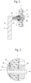
- the reference number 1 designates a section of a door or window frame into which a door or window handle 2 with a handle neck 21 with a handle part 22 is fixed by means of a holding element 5.
- the holding element 5 is preferably as in the own DE 20 2015 101 329 U1 trained, the functional description of which is hereby expressly referred to in this document.
- the door or window frame 1 has a receiving opening 8 for receiving an adapter 3.
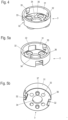
- FIG. 4 A first version of such an adapter is in Figure 4 A second variant of such an adapter is shown in the Figures 5a and 5b What both variants have in common is that the adapter 3 has a cylindrical casing 31 and a base 36 extending from the inner surface of the casing.
- the base is provided with a polygonal receptacle 34 and at least two holes 33.
- the holes 33 serve to accommodate screws 9 for fixing the adapter 3 to the window or door frame 1.
- the polygonal receptacle 34 arranged centrally here serves to guide a polygon 4, designed here as a square bar, which extends from a cavity in the interior of the handle neck 22 through the holding element 5 into a gear or a locking unit 11 in the window or door frame 1.
- a cover rosette 6 is provided to cover the holding element 5 from the visible side of the door or window frame 1.
- the door or window handle 2 is fixed to the holding element 5 via a fixing screw 7, which extends through a receptacle 23 in a circumferential surface of the handle neck 2 into a receptacle 53 in a receiving body 52 of the holding element 5, in which the polygon 4 is received.
- the casing 31 has two recesses 32 which serve to accommodate clamping elements 54 which can be moved radially out of a base body 51 of the holding element 5 and in particular are held pivotably on the base body 51.
- the recesses 32 are designed as through holes here. It is also conceivable to keep the outer surface of the casing 31 closed and to design the recesses 32 accordingly as blind holes.
- the recesses 32 are preferably made on opposite inner sides of the casing surface of the casing 31.
- two grooves 35 are preferably provided in the inner surface of the casing 31, which grooves serve to accommodate elevations projecting radially outward from the base body 51 of the holding element 5.
- the base 36 of this embodiment variant of the adapter 3 is star-shaped. Arms extend radially from the polygonal receptacle 34 towards the casing 31, in which the bores 33 are arranged.
- the base 36 is designed as a circular plate with corresponding holes 33 and a centrally arranged polygonal receptacle 34.
- pins 37 extending preferably perpendicular to the plane of the base are arranged, in particular molded onto them.
- the adapter 3 is preferably designed as an injection-molded part.
- the adapter 3 is first inserted into the receiving opening 8 of the door or window leaf 1 and fixed using the screws 9.
- the receiving opening 8 has a contoured contact surface 82 which is shaped in accordance with the star-shaped design of the base 36 of the adapter, so that the base 36 is positively fixed in the receiving opening 8 in a direction perpendicular to the longitudinal extension of the polygon 4, in which the polygon 4 is rotated when the door handle 2 is operated.
- the polygon 4 is then pushed through the polygon holder 34 of the adapter into the door or window frame 1 and into the locking unit 10, as shown in the Figures 2 and 3 shown.
- a raised portion 44 is formed on an outer surface of the polygon to limit the insertion depth of the polygon.
- the elevation can be introduced, for example, by a deformation, in particular in the form of a material displacement, of an outer edge of the base body 41 of the polygon 4, which is preferably square in cross section.
- the elevation 44 rests against a housing wall of the locking unit 11 facing the door or window handle 2, into which the polygon 4 is inserted.
- the polygon 4 is preferably provided as a hollow profile with a longitudinal bore 45 with an internal thread into which a locking screw 43 can be inserted.
- a longitudinal slot 42 extending in the direction of the longitudinal extent of the polygon is preferably introduced.
- the holding element 5 is then placed onto the polygon 4.
- the cover rosette 6 is then pushed onto the handle neck 22 of the door or window handle 2 and finally the door or window handle 2 is pushed with its handle neck 22 onto the receiving body 52 which is rotatably mounted in the base body 51 of the holding element 5 and fixed with the locking screw 7.
Landscapes
- Engineering & Computer Science (AREA)
- Mechanical Engineering (AREA)
- Hinges (AREA)
- Wing Frames And Configurations (AREA)
- Securing Of Glass Panes Or The Like (AREA)
Claims (10)
- Arrangement de poignée de porte ou de fenêtre (2) dans une ouverture de réception (8) d'un châssis de fenêtre (1), d'un vantail de porte ou similaire,- dans lequel une béquille (21) de la poignée de porte ou de fenêtre (2) est fixée sur un élément de maintien (5),- dans lequel l'élément de maintien (5) comprend un corps de base (51), un réceptacle (52) supporté dans le corps de base (5) avec possibilité de rotation et muni d'une ouverture de palier (55) pour recevoir et supporter un polygone (4) fixé dans la béquille (21) de la poignée de porte ou de fenêtre (2) et dépassant de celle-ci,- dans lequel un adaptateur (3) recevant l'élément de maintien (5) est fixé dans l'ouverture de réception (8),- dans lequel l'adaptateur comprend une enveloppe (31) munie d'au moins une découpe (32), une base (36) qui s'étend à partir d'une surface intérieure de l'enveloppe (31) et munie d'un logement de polygone (34) et au moins deux perçages (33),caractérisé en ce que l'élément de maintien (5) comprend au moins un élément de serrage (54) qui peut être sorti dans le sens radial du corps de base (51) de l'élément de maintien (5),l'au moins un élément de serrage (54) pouvant être déplacé d'une position de montage, dans laquelle l'élément de serrage (54) repose dans une découpe d'une surface d'enveloppe du corps de base (51), à une position de travail dans laquelle l'élément de serrage (54) dépasse de la découpe de la surface d'enveloppe du corps de base (51) vers l'extérieur dans le sens radial dans la découpe (32) de l'enveloppe (31) de l'adaptateur (3).
- Arrangement selon la revendication 1, caractérisé en ce que l'enveloppe (31) comporte deux découpes (32) qui sont réalisées sur des faces opposées l'une à l'autre.
- Arrangement selon la revendication 1 ou 2, caractérisé en ce que l'enveloppe (31) comporte au moins une rainure (35) destinée à recevoir une saillie qui dépasse du corps de base (51) de l'élément de maintien (5) vers l'extérieur dans le sens radial.
- Arrangement selon l'une des revendications précédentes, caractérisé en ce que l'enveloppe (31) est conformée comme une enveloppe cylindrique.
- Arrangement selon l'une des revendications précédentes, caractérisé en ce que la base (36) est en forme d'étoile, avec des bras qui s'étendent dans le sens radial du logement de polygone (34) vers l'enveloppe (31) et dans lesquels les perçages (33) sont disposés.
- Arrangement selon l'une des revendications 1 à 4, caractérisé en ce que la base (36) est conformée comme une plaque circulaire, des goujons (37) s'étendant à partir d'une face arrière de la base (36) tournée à l'opposé de l'élément de maintien (5).
- Arrangement selon l'une des revendications précédentes, caractérisé en ce que l'enveloppe (31) est réalisée comme une pièce moulée par injection.
- Arrangement selon l'une des revendications précédentes, caractérisé en ce que l'ouverture de réception (8) est adaptée aux dimensions extérieures de l'adaptateur (3), en particulier cylindrique.
- Arrangement selon l'une des revendications précédentes, caractérisé en ce que l'ouverture de réception (8) comporte une surface d'appui (82) profilée pour recevoir de manière fixe en rotation la base (36) de l'adaptateur (3).
- Arrangement selon l'une des revendications précédentes, caractérisé en ce qu'est formée sur une surface extérieure du polygone (4) une saillie (44) destinée à limiter la profondeur d'insertion du polygone (4) dans le châssis de fenêtre (1), le vantail ou similaire, la saillie (44) reposant, dans l'état monté de la poignée de porte ou de fenêtre (2), sur une paroi de boîtier tournée vers la poignée de porte ou de fenêtre (2) d'une unité de fermeture (11) dans laquelle le polygone (4) est inséré.
Applications Claiming Priority (2)
| Application Number | Priority Date | Filing Date | Title |
|---|---|---|---|
| DE202017103467.4U DE202017103467U1 (de) | 2017-06-09 | 2017-06-09 | Adapter zum Einbau eines Halteelements eines Tür- oder Fensterdrückers |
| PCT/EP2018/063164 WO2018224294A1 (fr) | 2017-06-09 | 2018-05-18 | Adaptateur servant au montage d'un élément de retenue d'une poignée de porte ou de fenêtre |
Publications (3)
| Publication Number | Publication Date |
|---|---|
| EP3635202A1 EP3635202A1 (fr) | 2020-04-15 |
| EP3635202B1 true EP3635202B1 (fr) | 2024-12-25 |
| EP3635202C0 EP3635202C0 (fr) | 2024-12-25 |
Family
ID=59410550
Family Applications (1)
| Application Number | Title | Priority Date | Filing Date |
|---|---|---|---|
| EP18729588.6A Active EP3635202B1 (fr) | 2017-06-09 | 2018-05-18 | Adaptateur servant au montage d'un élément de retenue d'une poignée de porte ou de fenêtre |
Country Status (5)
| Country | Link |
|---|---|
| EP (1) | EP3635202B1 (fr) |
| CN (2) | CN113431431B (fr) |
| DE (1) | DE202017103467U1 (fr) |
| ES (1) | ES3008284T3 (fr) |
| WO (1) | WO2018224294A1 (fr) |
Families Citing this family (7)
| Publication number | Priority date | Publication date | Assignee | Title |
|---|---|---|---|---|
| DE202018107399U1 (de) * | 2018-12-21 | 2019-01-14 | Franz Schneider Brakel Gmbh + Co Kg | Vorrichtung zur Fixierung eines Tür- oder Fensterdrückers |
| US11976494B2 (en) * | 2019-09-11 | 2024-05-07 | Carrier Corporation | Door handle assembly |
| WO2021050422A1 (fr) * | 2019-09-11 | 2021-03-18 | Carrier Corporation | Ensemble fouillot pour poignée de porte |
| BE1028725B1 (nl) * | 2020-10-22 | 2022-05-24 | Sobinco Fa | Rozetloze raam- of deurgreep |
| ES1295721Y (es) * | 2022-07-08 | 2023-02-23 | Sist Tecnicos Del Accesorio Y Componentes S L | Manilla para puertas y ventanas elevables de grandes dimensiones |
| DE102023109375A1 (de) * | 2023-04-13 | 2024-10-17 | SCHÜCO International KG | Flügel für ein Fenster oder eine Tür |
| PL446140A1 (pl) * | 2023-09-15 | 2025-03-17 | Fks Okucia Okienne I Drzwiowe Spółka Z Ograniczoną Odpowiedzialnością | Zespół klamki okiennej |
Citations (1)
| Publication number | Priority date | Publication date | Assignee | Title |
|---|---|---|---|---|
| EP2476823A2 (fr) * | 2011-01-17 | 2012-07-18 | Hoppe AG | Poignée d'actionnement |
Family Cites Families (11)
| Publication number | Priority date | Publication date | Assignee | Title |
|---|---|---|---|---|
| US5983683A (en) * | 1998-02-06 | 1999-11-16 | Shen; Mu-Lin | Adapter device for a key-in-lever type lock |
| US6048007A (en) * | 1998-09-28 | 2000-04-11 | Arrow Lock Manufacturing Company | Lever handle door lock with adapter |
| US6598440B1 (en) * | 1999-11-24 | 2003-07-29 | Newfrey Llc | Lockset mechanism having a semi-permanent mechanical connection |
| DE20317765U1 (de) * | 2003-01-09 | 2004-02-19 | Dorma Gmbh + Co. Kg | Beschlag |
| US7178842B2 (en) * | 2004-09-13 | 2007-02-20 | Newfrey, Llc | Push button lock mechanism for a handle set |
| CA2664863C (fr) * | 2006-09-29 | 2013-09-03 | Giacinto Rivadossi S.P.A. In Liquidazione | Dispositif de type serrure |
| DE102007046538A1 (de) * | 2007-09-27 | 2009-04-02 | Dorma Gmbh + Co. Kg | Griffbefestigung und Beschlag mit Griffbefestigung |
| DE102014104141A1 (de) * | 2014-03-25 | 2015-10-01 | Hoppe Ag | Betätigungshandhabe |
| DE202015101329U1 (de) | 2015-03-16 | 2016-06-20 | Franz Schneider Brakel Gmbh + Co Kg | Halteelement für einen Tür- oder Fensterdrücker und Anordnung eines Tür- oder Fensterdrückers an einer Aufnahmeöffnung eines Fensterrahmens, eines Türblatts oder dergleichen |
| JP6562540B2 (ja) * | 2015-04-23 | 2019-08-21 | 河淳株式会社 | ドア錠の台座構造体 |
| CN106545228B (zh) * | 2016-12-09 | 2018-10-16 | 广东电网有限责任公司电力调度控制中心 | 一种可自供电的无源电子锁具 |
-
2017
- 2017-06-09 DE DE202017103467.4U patent/DE202017103467U1/de active Active
-
2018
- 2018-05-18 WO PCT/EP2018/063164 patent/WO2018224294A1/fr not_active Ceased
- 2018-05-18 ES ES18729588T patent/ES3008284T3/es active Active
- 2018-05-18 EP EP18729588.6A patent/EP3635202B1/fr active Active
- 2018-05-18 CN CN202110871903.7A patent/CN113431431B/zh active Active
- 2018-05-18 CN CN201880036808.1A patent/CN110709567A/zh active Pending
Patent Citations (1)
| Publication number | Priority date | Publication date | Assignee | Title |
|---|---|---|---|---|
| EP2476823A2 (fr) * | 2011-01-17 | 2012-07-18 | Hoppe AG | Poignée d'actionnement |
Also Published As
| Publication number | Publication date |
|---|---|
| DE202017103467U1 (de) | 2017-07-07 |
| ES3008284T3 (en) | 2025-03-21 |
| WO2018224294A1 (fr) | 2018-12-13 |
| CN110709567A (zh) | 2020-01-17 |
| EP3635202A1 (fr) | 2020-04-15 |
| CN113431431A (zh) | 2021-09-24 |
| EP3635202C0 (fr) | 2024-12-25 |
| CN113431431B (zh) | 2022-07-08 |
Similar Documents
| Publication | Publication Date | Title |
|---|---|---|
| EP3635202B1 (fr) | Adaptateur servant au montage d'un élément de retenue d'une poignée de porte ou de fenêtre | |
| EP2840203B1 (fr) | Ferrure de porte ou de fenêtre dotée d'une plaque de couverture en plusieurs parties | |
| EP1723298B1 (fr) | Fermeture a fixer dans des ouvertures menagees dans une paroi mince | |
| EP3271530B1 (fr) | Élément de maintien pour une poignée de porte ou de fenêtre et agencement d'une poignée de porte ou de fenêtre au niveau d'une ouverture de réception d'un cadre de fenêtre, d'un battant de porte ou similaire | |
| EP2055867A1 (fr) | Poignée dotée d'une garniture de fermeture | |
| EP3867465B1 (fr) | Dispositif pour fixer une poignée de porte ou de fenêtre | |
| EP1022413B1 (fr) | Plaque de montage | |
| DE202009000422U1 (de) | Betätigungshandhabe | |
| EP2796645B1 (fr) | Serrure à pêne dormant d'un meuble | |
| EP3760816A1 (fr) | Dispositif de maintien pour une poignée de porte ou de fenêtre | |
| DE4442125C1 (de) | Möbelschloß oder Verschluß | |
| DE202019102648U1 (de) | Drückerlagerung eines Tür- oder Fensterdrückers | |
| EP3867467B1 (fr) | Support de béquille, béquille de porte ou de fenêtre comprenant un support de béquille | |
| EP1621123B1 (fr) | Elément pivotant pour un objet mural d'équipement sanitaire | |
| CH709435A2 (de) | Einsteckschloss für einen Flügel einer Tür oder eines Fensters. | |
| EP3543433B1 (fr) | Dispositif de cintrage pour une garniture de poignée de porte et garniture de poignée de porte dotée d'un tel dispositif de positionnement | |
| DE102004012278B4 (de) | Rosette für einen Türbeschlag | |
| EP3363969A1 (fr) | Poignée d'actionnement | |
| EP3434145B1 (fr) | Dispositif de suspension caché et meuble suspendu | |
| DE202019105897U1 (de) | Drückerlagerung mit einem Tür- oder Fensterdrücker | |
| EP2177696B1 (fr) | Rebord de porte ou de fenêtre | |
| DE102005057766B3 (de) | Beschlag für Türen, Fenster oder dergleichen | |
| DE202007016708U1 (de) | Band für Türen, Fenster o.dgl. | |
| DE20108224U1 (de) | Möbel, insbesondere Schrank | |
| EP2362045A2 (fr) | Porte pour une armoire électrique |
Legal Events
| Date | Code | Title | Description |
|---|---|---|---|
| STAA | Information on the status of an ep patent application or granted ep patent |
Free format text: STATUS: UNKNOWN |
|
| STAA | Information on the status of an ep patent application or granted ep patent |
Free format text: STATUS: THE INTERNATIONAL PUBLICATION HAS BEEN MADE |
|
| PUAI | Public reference made under article 153(3) epc to a published international application that has entered the european phase |
Free format text: ORIGINAL CODE: 0009012 |
|
| STAA | Information on the status of an ep patent application or granted ep patent |
Free format text: STATUS: REQUEST FOR EXAMINATION WAS MADE |
|
| 17P | Request for examination filed |
Effective date: 20191203 |
|
| AK | Designated contracting states |
Kind code of ref document: A1 Designated state(s): AL AT BE BG CH CY CZ DE DK EE ES FI FR GB GR HR HU IE IS IT LI LT LU LV MC MK MT NL NO PL PT RO RS SE SI SK SM TR |
|
| AX | Request for extension of the european patent |
Extension state: BA ME |
|
| DAV | Request for validation of the european patent (deleted) | ||
| DAX | Request for extension of the european patent (deleted) | ||
| STAA | Information on the status of an ep patent application or granted ep patent |
Free format text: STATUS: EXAMINATION IS IN PROGRESS |
|
| 17Q | First examination report despatched |
Effective date: 20230510 |
|
| GRAP | Despatch of communication of intention to grant a patent |
Free format text: ORIGINAL CODE: EPIDOSNIGR1 |
|
| STAA | Information on the status of an ep patent application or granted ep patent |
Free format text: STATUS: GRANT OF PATENT IS INTENDED |
|
| INTG | Intention to grant announced |
Effective date: 20240920 |
|
| RIN1 | Information on inventor provided before grant (corrected) |
Inventor name: ZIMMERMANN, SASCHA |
|
| GRAS | Grant fee paid |
Free format text: ORIGINAL CODE: EPIDOSNIGR3 |
|
| GRAA | (expected) grant |
Free format text: ORIGINAL CODE: 0009210 |
|
| STAA | Information on the status of an ep patent application or granted ep patent |
Free format text: STATUS: THE PATENT HAS BEEN GRANTED |
|
| AK | Designated contracting states |
Kind code of ref document: B1 Designated state(s): AL AT BE BG CH CY CZ DE DK EE ES FI FR GB GR HR HU IE IS IT LI LT LU LV MC MK MT NL NO PL PT RO RS SE SI SK SM TR |
|
| REG | Reference to a national code |
Ref country code: GB Ref legal event code: FG4D Free format text: NOT ENGLISH |
|
| REG | Reference to a national code |
Ref country code: CH Ref legal event code: EP |
|
| REG | Reference to a national code |
Ref country code: DE Ref legal event code: R096 Ref document number: 502018015446 Country of ref document: DE |
|
| REG | Reference to a national code |
Ref country code: IE Ref legal event code: FG4D Free format text: LANGUAGE OF EP DOCUMENT: GERMAN |
|
| U01 | Request for unitary effect filed |
Effective date: 20250117 |
|
| U07 | Unitary effect registered |
Designated state(s): AT BE BG DE DK EE FI FR IT LT LU LV MT NL PT RO SE SI Effective date: 20250124 |
|
| REG | Reference to a national code |
Ref country code: ES Ref legal event code: FG2A Ref document number: 3008284 Country of ref document: ES Kind code of ref document: T3 Effective date: 20250321 |
|
| PG25 | Lapsed in a contracting state [announced via postgrant information from national office to epo] |
Ref country code: NO Free format text: LAPSE BECAUSE OF FAILURE TO SUBMIT A TRANSLATION OF THE DESCRIPTION OR TO PAY THE FEE WITHIN THE PRESCRIBED TIME-LIMIT Effective date: 20250325 |
|
| PG25 | Lapsed in a contracting state [announced via postgrant information from national office to epo] |
Ref country code: GR Free format text: LAPSE BECAUSE OF FAILURE TO SUBMIT A TRANSLATION OF THE DESCRIPTION OR TO PAY THE FEE WITHIN THE PRESCRIBED TIME-LIMIT Effective date: 20250326 |
|
| PG25 | Lapsed in a contracting state [announced via postgrant information from national office to epo] |
Ref country code: RS Free format text: LAPSE BECAUSE OF FAILURE TO SUBMIT A TRANSLATION OF THE DESCRIPTION OR TO PAY THE FEE WITHIN THE PRESCRIBED TIME-LIMIT Effective date: 20250325 |
|
| U20 | Renewal fee for the european patent with unitary effect paid |
Year of fee payment: 8 Effective date: 20250326 |
|
| PG25 | Lapsed in a contracting state [announced via postgrant information from national office to epo] |
Ref country code: SM Free format text: LAPSE BECAUSE OF FAILURE TO SUBMIT A TRANSLATION OF THE DESCRIPTION OR TO PAY THE FEE WITHIN THE PRESCRIBED TIME-LIMIT Effective date: 20241225 |
|
| PG25 | Lapsed in a contracting state [announced via postgrant information from national office to epo] |
Ref country code: PL Free format text: LAPSE BECAUSE OF FAILURE TO SUBMIT A TRANSLATION OF THE DESCRIPTION OR TO PAY THE FEE WITHIN THE PRESCRIBED TIME-LIMIT Effective date: 20241225 |
|
| PGFP | Annual fee paid to national office [announced via postgrant information from national office to epo] |
Ref country code: ES Payment date: 20250616 Year of fee payment: 8 Ref country code: GB Payment date: 20250415 Year of fee payment: 8 |
|
| PG25 | Lapsed in a contracting state [announced via postgrant information from national office to epo] |
Ref country code: IS Free format text: LAPSE BECAUSE OF FAILURE TO SUBMIT A TRANSLATION OF THE DESCRIPTION OR TO PAY THE FEE WITHIN THE PRESCRIBED TIME-LIMIT Effective date: 20250425 |
|
| PGFP | Annual fee paid to national office [announced via postgrant information from national office to epo] |
Ref country code: CH Payment date: 20250605 Year of fee payment: 8 |
|
| PG25 | Lapsed in a contracting state [announced via postgrant information from national office to epo] |
Ref country code: SK Free format text: LAPSE BECAUSE OF FAILURE TO SUBMIT A TRANSLATION OF THE DESCRIPTION OR TO PAY THE FEE WITHIN THE PRESCRIBED TIME-LIMIT Effective date: 20241225 |
|
| PG25 | Lapsed in a contracting state [announced via postgrant information from national office to epo] |
Ref country code: CZ Free format text: LAPSE BECAUSE OF FAILURE TO SUBMIT A TRANSLATION OF THE DESCRIPTION OR TO PAY THE FEE WITHIN THE PRESCRIBED TIME-LIMIT Effective date: 20241225 |
|
| PLBE | No opposition filed within time limit |
Free format text: ORIGINAL CODE: 0009261 |
|
| STAA | Information on the status of an ep patent application or granted ep patent |
Free format text: STATUS: NO OPPOSITION FILED WITHIN TIME LIMIT |
|
| 26N | No opposition filed |
Effective date: 20250926 |
|
| PG25 | Lapsed in a contracting state [announced via postgrant information from national office to epo] |
Ref country code: MC Free format text: LAPSE BECAUSE OF FAILURE TO SUBMIT A TRANSLATION OF THE DESCRIPTION OR TO PAY THE FEE WITHIN THE PRESCRIBED TIME-LIMIT Effective date: 20241225 |
|
| U20 | Renewal fee for the european patent with unitary effect paid |
Year of fee payment: 9 Effective date: 20260302 |
|
| PG25 | Lapsed in a contracting state [announced via postgrant information from national office to epo] |
Ref country code: IE Free format text: LAPSE BECAUSE OF NON-PAYMENT OF DUE FEES Effective date: 20250518 |
|
| PG25 | Lapsed in a contracting state [announced via postgrant information from national office to epo] |
Ref country code: HR Free format text: LAPSE BECAUSE OF FAILURE TO SUBMIT A TRANSLATION OF THE DESCRIPTION OR TO PAY THE FEE WITHIN THE PRESCRIBED TIME-LIMIT Effective date: 20241225 |