EP2476914A1 - Pompe électrique pour le refroidissement d'un moteur à combustion interne - Google Patents
Pompe électrique pour le refroidissement d'un moteur à combustion interne Download PDFInfo
- Publication number
- EP2476914A1 EP2476914A1 EP11150865A EP11150865A EP2476914A1 EP 2476914 A1 EP2476914 A1 EP 2476914A1 EP 11150865 A EP11150865 A EP 11150865A EP 11150865 A EP11150865 A EP 11150865A EP 2476914 A1 EP2476914 A1 EP 2476914A1
- Authority
- EP
- European Patent Office
- Prior art keywords
- coolant pump
- board
- cooling
- area
- partition
- Prior art date
- Legal status (The legal status is an assumption and is not a legal conclusion. Google has not performed a legal analysis and makes no representation as to the accuracy of the status listed.)
- Granted
Links
Images


Classifications
-
- H—ELECTRICITY
- H05—ELECTRIC TECHNIQUES NOT OTHERWISE PROVIDED FOR
- H05K—PRINTED CIRCUITS; CASINGS OR CONSTRUCTIONAL DETAILS OF ELECTRIC APPARATUS; MANUFACTURE OF ASSEMBLAGES OF ELECTRICAL COMPONENTS
- H05K7/00—Constructional details common to different types of electric apparatus
- H05K7/20—Modifications to facilitate cooling, ventilating, or heating
- H05K7/2089—Modifications to facilitate cooling, ventilating, or heating for power electronics, e.g. for inverters for controlling motor
- H05K7/209—Heat transfer by conduction from internal heat source to heat radiating structure
-
- F—MECHANICAL ENGINEERING; LIGHTING; HEATING; WEAPONS; BLASTING
- F04—POSITIVE - DISPLACEMENT MACHINES FOR LIQUIDS; PUMPS FOR LIQUIDS OR ELASTIC FLUIDS
- F04B—POSITIVE-DISPLACEMENT MACHINES FOR LIQUIDS; PUMPS
- F04B17/00—Pumps characterised by combination with, or adaptation to, specific driving engines or motors
- F04B17/03—Pumps characterised by combination with, or adaptation to, specific driving engines or motors driven by electric motors
-
- F—MECHANICAL ENGINEERING; LIGHTING; HEATING; WEAPONS; BLASTING
- F04—POSITIVE - DISPLACEMENT MACHINES FOR LIQUIDS; PUMPS FOR LIQUIDS OR ELASTIC FLUIDS
- F04D—NON-POSITIVE-DISPLACEMENT PUMPS
- F04D13/00—Pumping installations or systems
- F04D13/02—Units comprising pumps and their driving means
- F04D13/06—Units comprising pumps and their driving means the pump being electrically driven
- F04D13/0686—Mechanical details of the pump control unit
-
- F—MECHANICAL ENGINEERING; LIGHTING; HEATING; WEAPONS; BLASTING
- F04—POSITIVE - DISPLACEMENT MACHINES FOR LIQUIDS; PUMPS FOR LIQUIDS OR ELASTIC FLUIDS
- F04D—NON-POSITIVE-DISPLACEMENT PUMPS
- F04D29/00—Details, component parts, or accessories
- F04D29/58—Cooling; Heating; Diminishing heat transfer
- F04D29/5813—Cooling the control unit
Definitions
- the invention relates to an electric vehicle coolant pump for supplying an internal combustion engine with coolant, wherein the brushless electric motor is electronically commutated.
- An electric vehicle coolant pump with a brushless electronically commutated electric motor as a drive motor has a control electronics and power semiconductors that can generate heat during operation.
- a coolant pump runs during the operation of the motor vehicle to be supplied with coolant virtually always, albeit at different speeds. Under unfavorable conditions, for example at full load of the internal combustion engine, low vehicle speed and high outside temperatures, the coolant pump has to run for a long time under full load.
- the significant heat loss of the power semiconductor must be reliably dissipated to prevent destruction of the power semiconductor.
- the object of the invention is in contrast to provide an electric vehicle coolant pump with an electronically commutated electric motor in which the power semiconductor well cooled and the cooling vanes of the power semiconductor are contacted directly with a conductor on the board.
- the coolant pump has a wet area, in which a pump wheel and a permanent magnet, so permanently excited, motor rotor of the electronically commutated electric motor are arranged. Furthermore, the coolant pump has a dry area, in which inter alia an electrical circuit board is arranged, which carries a plurality of power semiconductors, each with a cooling lug.
- the power semiconductors serve the direct control of the stator-side motor coils.
- the wet area and the dry area are separated by an electrically conductive and lying in a transverse plane partition.
- the partition wall is preferably made of electrically conductive metal, but in principle may also consist of electrically non-conductive material, for example of plastic. Lying in a transverse plane and adjacent to the dividing wall, a circuit board is arranged, wherein the power semiconductors are arranged on the proximal side of the circuit board facing the dividing wall.
- the electrical connections of the power semiconductors, including the cooling vanes, which also each represent an electrical connection, are soldered to corresponding printed conductors on the circuit board.
- All cooling lugs of the power semiconductors are each arranged on a separate conductor track and soldered to it, that is, the cooling lugs are electrically separated from each other.
- the interconnected with the cooling lugs traces lie with their the surface of the respective cooling lance protruding areas on the partition, wherein between the partition wall and the conductor track an electrically non-conductive heat conducting means is provided, which electrically isolates the conductor track from the partition wall, but conducts heat well.
- a heat-conducting foil, a thermal paste or a heat-conducting adhesive is suitable as the heat-conducting agent.
- the conductor track on which the cooling lug is soldered therefore, must have a larger area than the cooling lug itself, or as the surface of the cooling lug connected to the conductor lane. Only the area of the relevant conductor lane projecting beyond the cooling lug rests on the electrically non-conductive heat conducting means , which in turn rests directly on the partition. On the side facing away from the board of the partition is the wet area, which is why the circulating coolant there can dissipate large amounts of heat from the partition.
- the heat flow of the waste heat of the power semiconductor thus runs from its cooling lug on the conductor track on which the cooling lug is soldered, and the electrically non-conductive heat conduction to the partition, from where the heat is dissipated by the coolant.
- an effective cooling of the power semiconductor is possible, wherein the cooling vanes of the power semiconductor are still electrically connected or soldered in each case with its own trace of the board.
- the dividing wall has, on its side facing the circuit board, for each power semiconductor in each case a semiconductor recess into which the semiconductor projects axially.
- the semiconductor recesses are necessary so that the partition with its base, with the interposition of the heat-conducting, can rest directly on the conductor.
- On the side facing the partition of the board only the power semiconductors are arranged, and no other electronic components are provided.
- corresponding plated-through holes are provided, which, however, exclusively make the electrical contact and are not suitable for heat transport.
- the electric motor preferably has a containment shell which separates the wet area from a dry area in which inter alia the stator-side motor coils are arranged.
- the drying area in which the motor coils are arranged may be separate from the drying area in which the board is arranged.
- the partition lying in a transverse plane is part of the can, so that the partition is directly flowed through and cooled by the coolant.
- the surface of the conductor is at least twice as large, preferably at least three times as large, and more preferably at least five times as large as the surface of the respective cooling lug with which it is fixed or soldered on the conductor.
- FIG. 1 is shown in longitudinal section and schematically an electric motor vehicle coolant pump 10, which pumps a liquid coolant in a coolant circuit, which serves for cooling an internal combustion engine, not shown.
- the coolant pump 10 has an electric brushless drive motor 15, which is electronically commutated.
- the coolant pump 10 has a multi-part housing 11 which is divided on the inside by a split pot 17 into a wet area 60 and a dry area 62.
- the containment shell 17 is formed by a non-magnetic plastic pot sleeve 19, which is L-shaped in cross-section, and an electrically conductive metal partition 24, which lies in a transverse plane.
- the rotor disposed in the wet section 60 includes a dual bearing shaft 12, a magnetically permanently energized motor rotor 16, and a pump rotor 14 that pumps coolant from an axial coolant inlet 18 to a radial coolant outlet 20.
- a plurality of stator coils 22, which are arranged on the proximal side of the partition wall 24, are arranged radially outside the motor rotor 16 and the cylindrical section of the cup sleeve 19 and at the same axial position.
- an electrical circuit board 28 with the entire electronics for controlling the stator coils 19 is provided in a circuit board space 51.
- the board 28 lies in a transverse plane and is equipped on both sides, wherein on the distal side of the board-plate 40, a plurality of control electronics elements 36, which form the control electronics 36, are soldered on conductor tracks, and on the proximal side of the board 28 only a plurality of identical power semiconductors 30,30 'are arranged, which have corresponding Through holes 64 are controlled by the control electronics 36.
- the power semiconductors 30, 30 ' may be MOSFET transistors.
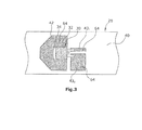
- the power semiconductors 30, 30 ' are mounted horizontally on the circuit board 28, each power semiconductor 30, 30' having a cooling lug 34 whose area is greater than the corresponding area of the semiconductor body 32.
- the cooling lug 34,34 ' is in each case an electrical connection of the power semiconductor and is soldered over the entire area with solder 35, each on a large-area conductor track 42,42'.
- the proximal side of the board 28 is covered with an electrically nonconductive heat conducting means 44 in the form of a heat conducting foil, which has openings 45, 45 'corresponding only in the areas of the power semiconductors 30, 30'.
- the heat-conducting means 44 is thermally conductive on the distal side 80 of the partition wall 24, which in each case in the region of the power semiconductor 30,30 'and the corresponding heat-conducting openings 45,45' corresponding recesses 50,50 'has, in which the semiconductor Body 32,32 'respectively protrudes.
- the recesses 50,50 ' are axially non-continuous, so that the partition wall 24 is completely liquid-tight.
- the area of the conductor track 42, 42 ' is in each case at least 4 to 5 times the area of the cooling vane 34, 34' of the relevant power semiconductor 30, 30 '.
- the other terminals of the power semiconductor are soldered to corresponding tracks 43 1 and 43 2 .
- the board space 51 is closed by a cover 26.
Landscapes
- Engineering & Computer Science (AREA)
- Mechanical Engineering (AREA)
- General Engineering & Computer Science (AREA)
- Physics & Mathematics (AREA)
- Thermal Sciences (AREA)
- Microelectronics & Electronic Packaging (AREA)
- Cooling Or The Like Of Semiconductors Or Solid State Devices (AREA)
- Structures Of Non-Positive Displacement Pumps (AREA)
- Cooling Or The Like Of Electrical Apparatus (AREA)
- Motor Or Generator Cooling System (AREA)
Priority Applications (4)
| Application Number | Priority Date | Filing Date | Title |
|---|---|---|---|
| EP11150865.1A EP2476914B1 (fr) | 2011-01-13 | 2011-01-13 | Pompe électrique pour le refroidissement d'un moteur à combustion interne |
| US13/979,377 US20140010684A1 (en) | 2011-01-13 | 2011-07-27 | Electrical motor vehicle coolant pump |
| CN201180069169.7A CN103443474B (zh) | 2011-01-13 | 2011-07-27 | 电动车辆冷却剂泵 |
| PCT/EP2011/062864 WO2012095192A1 (fr) | 2011-01-13 | 2011-07-27 | Pompe électrique pour fluide de refroidissement de véhicule |
Applications Claiming Priority (1)
| Application Number | Priority Date | Filing Date | Title |
|---|---|---|---|
| EP11150865.1A EP2476914B1 (fr) | 2011-01-13 | 2011-01-13 | Pompe électrique pour le refroidissement d'un moteur à combustion interne |
Publications (2)
| Publication Number | Publication Date |
|---|---|
| EP2476914A1 true EP2476914A1 (fr) | 2012-07-18 |
| EP2476914B1 EP2476914B1 (fr) | 2017-08-02 |
Family
ID=44140682
Family Applications (1)
| Application Number | Title | Priority Date | Filing Date |
|---|---|---|---|
| EP11150865.1A Active EP2476914B1 (fr) | 2011-01-13 | 2011-01-13 | Pompe électrique pour le refroidissement d'un moteur à combustion interne |
Country Status (4)
| Country | Link |
|---|---|
| US (1) | US20140010684A1 (fr) |
| EP (1) | EP2476914B1 (fr) |
| CN (1) | CN103443474B (fr) |
| WO (1) | WO2012095192A1 (fr) |
Cited By (9)
| Publication number | Priority date | Publication date | Assignee | Title |
|---|---|---|---|---|
| EP2725691A1 (fr) * | 2012-10-29 | 2014-04-30 | Pierburg Pump Technology GmbH | Agrégat auxiliaire électrique d'un véhicule |
| DE102012222358A1 (de) | 2012-12-05 | 2014-06-05 | Mahle International Gmbh | Elektrische Flüssigkeitspumpe |
| DE102012222359A1 (de) | 2012-12-05 | 2014-06-05 | Mahle International Gmbh | Elektrische Flüssigkeitspumpe |
| DE102013202335A1 (de) | 2013-02-13 | 2014-08-14 | Mahle International Gmbh | Elektrische Fluidpumpe |
| EP2947324A1 (fr) | 2014-05-22 | 2015-11-25 | Pierburg Pump Technology GmbH | Groupe auxiliaire électrique d'un véhicule |
| DE102014016481A1 (de) * | 2014-11-07 | 2016-05-12 | Brose Fahrzeugteile GmbH & Co. Kommanditgesellschaft, Würzburg | Elektromotorische Wasserpumpe |
| WO2019166080A1 (fr) | 2018-02-28 | 2019-09-06 | Pierburg Pump Technology Gmbh | Groupe auxiliaire électrique de véhicule automobile |
| AT521284A1 (de) * | 2018-05-22 | 2019-12-15 | Tcg Unitech Systemtechnik Gmbh | Kühlmittelpumpe |
| EP2979348B1 (fr) * | 2013-03-25 | 2020-04-29 | Pierburg Pump Technology GmbH | Pompe electronique de fluide pour véhicule automobile |
Families Citing this family (9)
| Publication number | Priority date | Publication date | Assignee | Title |
|---|---|---|---|---|
| US20150176551A1 (en) * | 2013-12-20 | 2015-06-25 | Michael R. Teets | Integrated pwm fuel pump driver module |
| DE102015214785B3 (de) * | 2015-08-03 | 2016-08-04 | Magna powertrain gmbh & co kg | Elektrischer Verdichter |
| CN106481567B (zh) * | 2015-08-26 | 2020-10-16 | 德昌电机(深圳)有限公司 | 电动液泵 |
| CN113202776B (zh) | 2017-08-23 | 2023-09-15 | 浙江三花智能控制股份有限公司 | 电动泵 |
| CN109958660A (zh) * | 2017-12-22 | 2019-07-02 | 盾安环境技术有限公司 | 一种散热结构及电子水泵 |
| JP7027910B2 (ja) * | 2018-01-25 | 2022-03-02 | トヨタ自動車株式会社 | 電動車両 |
| CN110541819B (zh) | 2018-05-28 | 2020-11-20 | 杭州三花研究院有限公司 | 电子油泵 |
| KR102221809B1 (ko) * | 2019-09-16 | 2021-03-03 | 주식회사 코아비스 | 제어부 일체형 모터 및 이를 포함한 워터 펌프 |
| DE102020106796A1 (de) | 2020-03-12 | 2021-09-16 | Schwäbische Hüttenwerke Automotive GmbH | Pumpeneinsatz und Pumpenanordnung mit einem solchen Pumpeneinsatz |
Citations (2)
| Publication number | Priority date | Publication date | Assignee | Title |
|---|---|---|---|---|
| US20070206357A1 (en) * | 2004-05-05 | 2007-09-06 | Siemens Ag Osterreich | Arrangement for cooling SMD power components on a printed circuit board |
| DE102007054060A1 (de) | 2006-11-20 | 2008-05-29 | Aisan Kogyo Kabushiki Kaisha, Obu | Fluidpumpe |
Family Cites Families (6)
| Publication number | Priority date | Publication date | Assignee | Title |
|---|---|---|---|---|
| DE19903078A1 (de) * | 1999-01-27 | 2000-08-03 | Wilo Gmbh | Spalttopf für Kreiselpumpe |
| US6377462B1 (en) * | 2001-01-09 | 2002-04-23 | Deere & Company | Circuit board assembly with heat sinking |
| US20070022979A1 (en) * | 2005-08-01 | 2007-02-01 | The Timken Company | Coolant pump for internal combustion engine |
| US7296543B2 (en) * | 2006-04-06 | 2007-11-20 | Gm Global Technology Operations, Inc. | Engine coolant pump drive system and apparatus for a vehicle |
| JP2009283741A (ja) * | 2008-05-23 | 2009-12-03 | Fuji Electric Device Technology Co Ltd | 半導体装置 |
| EP2253847B1 (fr) * | 2009-05-18 | 2019-07-03 | Pierburg Pump Technology GmbH | Pompe à paillettes à lubrifiant à capacité variable |
-
2011
- 2011-01-13 EP EP11150865.1A patent/EP2476914B1/fr active Active
- 2011-07-27 US US13/979,377 patent/US20140010684A1/en not_active Abandoned
- 2011-07-27 CN CN201180069169.7A patent/CN103443474B/zh active Active
- 2011-07-27 WO PCT/EP2011/062864 patent/WO2012095192A1/fr not_active Ceased
Patent Citations (2)
| Publication number | Priority date | Publication date | Assignee | Title |
|---|---|---|---|---|
| US20070206357A1 (en) * | 2004-05-05 | 2007-09-06 | Siemens Ag Osterreich | Arrangement for cooling SMD power components on a printed circuit board |
| DE102007054060A1 (de) | 2006-11-20 | 2008-05-29 | Aisan Kogyo Kabushiki Kaisha, Obu | Fluidpumpe |
Cited By (13)
| Publication number | Priority date | Publication date | Assignee | Title |
|---|---|---|---|---|
| EP2725691A1 (fr) * | 2012-10-29 | 2014-04-30 | Pierburg Pump Technology GmbH | Agrégat auxiliaire électrique d'un véhicule |
| DE102012222358A1 (de) | 2012-12-05 | 2014-06-05 | Mahle International Gmbh | Elektrische Flüssigkeitspumpe |
| DE102012222359A1 (de) | 2012-12-05 | 2014-06-05 | Mahle International Gmbh | Elektrische Flüssigkeitspumpe |
| US9366259B2 (en) | 2012-12-05 | 2016-06-14 | Mahle International Gmbh | Electric fluid pump |
| DE102013202335A1 (de) | 2013-02-13 | 2014-08-14 | Mahle International Gmbh | Elektrische Fluidpumpe |
| WO2014124975A2 (fr) | 2013-02-13 | 2014-08-21 | Mahle International Gmbh | Pompe à fluide électrique |
| DE112014000797B4 (de) | 2013-02-13 | 2025-04-24 | Mahle International Gmbh | Elektrische Fluidpumpe |
| EP2979348B1 (fr) * | 2013-03-25 | 2020-04-29 | Pierburg Pump Technology GmbH | Pompe electronique de fluide pour véhicule automobile |
| EP2947324A1 (fr) | 2014-05-22 | 2015-11-25 | Pierburg Pump Technology GmbH | Groupe auxiliaire électrique d'un véhicule |
| DE102014016481A1 (de) * | 2014-11-07 | 2016-05-12 | Brose Fahrzeugteile GmbH & Co. Kommanditgesellschaft, Würzburg | Elektromotorische Wasserpumpe |
| WO2019166080A1 (fr) | 2018-02-28 | 2019-09-06 | Pierburg Pump Technology Gmbh | Groupe auxiliaire électrique de véhicule automobile |
| AT521284A1 (de) * | 2018-05-22 | 2019-12-15 | Tcg Unitech Systemtechnik Gmbh | Kühlmittelpumpe |
| AT521284B1 (de) * | 2018-05-22 | 2022-08-15 | Tcg Unitech Systemtechnik Gmbh | Kühlmittelpumpe |
Also Published As
| Publication number | Publication date |
|---|---|
| CN103443474A (zh) | 2013-12-11 |
| CN103443474B (zh) | 2016-06-29 |
| WO2012095192A1 (fr) | 2012-07-19 |
| EP2476914B1 (fr) | 2017-08-02 |
| US20140010684A1 (en) | 2014-01-09 |
Similar Documents
| Publication | Publication Date | Title |
|---|---|---|
| EP2476914B1 (fr) | Pompe électrique pour le refroidissement d'un moteur à combustion interne | |
| EP3631966B1 (fr) | Véhicule automobile et dispositif onduleur pour un véhicule automobile | |
| DE102011002005B4 (de) | Halbleitermodul und motorisierte Gerätschaft, die dieses verwendet | |
| DE112010002715B4 (de) | Antriebsvorrichtung | |
| EP1454400B1 (fr) | Unite d'entrainement electrique | |
| EP2905471B1 (fr) | Pompe de liquide de refroidissement électrique de véhicule automobile | |
| DE102012104377B4 (de) | Halbleitervorrichtung und Antriebsvorrichtung, die eine Halbleitervorrichtung aufweist | |
| DE112015006036T5 (de) | Motorantriebs-steuerungseinrichtung für eine elektrische servolenkung | |
| DE102010017519A1 (de) | Motorvorrichtung mit integrierter elektronischer Schaltung | |
| DE102016223889A1 (de) | Stapelbares Elektronikmodul, Wechselrichter und Kraftfahrzeugantriebsstrang | |
| EP3472470B1 (fr) | Pompe à fluide électrique pour un véhicule automobile | |
| EP3762964B1 (fr) | Dispositif de refroidissement pour refroidir un composant de puissance | |
| DE102018111404A1 (de) | Motor, Leiterplatte und Motorkühlmodul mit dem Motor | |
| DE102021202543A1 (de) | Drehende elektrische maschine | |
| EP3759802B1 (fr) | Groupe auxiliaire électrique de véhicule automobile | |
| EP1866546B1 (fr) | Pompe a rotor noye | |
| EP3522341A1 (fr) | Entraînement électrique ayant un circuit électronique de puissance | |
| DE102013018840B3 (de) | Elektromotorische Wasserpumpe | |
| DE19904162C2 (de) | Brennstoff-Elektromotorpumpe | |
| EP3940239A1 (fr) | Turbomachine avec canal de refroidissement | |
| DE10045597C1 (de) | Pumpe mit einem elektronisch kommutierten Gleichstrommotor | |
| WO2013037449A2 (fr) | Groupe électro-pompe | |
| WO2020007712A1 (fr) | Système pourvu d'un boîtier et d'un circuit d'électronique de puissance agencé dans ce dernier sur un fond de boîtier | |
| DE102013202335A1 (de) | Elektrische Fluidpumpe | |
| EP2082636B1 (fr) | Unité d'entrainement et procédé pour faire fonctionner ladite unité d'entrainement |
Legal Events
| Date | Code | Title | Description |
|---|---|---|---|
| PUAI | Public reference made under article 153(3) epc to a published international application that has entered the european phase |
Free format text: ORIGINAL CODE: 0009012 |
|
| AK | Designated contracting states |
Kind code of ref document: A1 Designated state(s): AL AT BE BG CH CY CZ DE DK EE ES FI FR GB GR HR HU IE IS IT LI LT LU LV MC MK MT NL NO PL PT RO RS SE SI SK SM TR |
|
| AX | Request for extension of the european patent |
Extension state: BA ME |
|
| 17P | Request for examination filed |
Effective date: 20130110 |
|
| GRAP | Despatch of communication of intention to grant a patent |
Free format text: ORIGINAL CODE: EPIDOSNIGR1 |
|
| STAA | Information on the status of an ep patent application or granted ep patent |
Free format text: STATUS: GRANT OF PATENT IS INTENDED |
|
| INTG | Intention to grant announced |
Effective date: 20170425 |
|
| GRAS | Grant fee paid |
Free format text: ORIGINAL CODE: EPIDOSNIGR3 |
|
| GRAA | (expected) grant |
Free format text: ORIGINAL CODE: 0009210 |
|
| STAA | Information on the status of an ep patent application or granted ep patent |
Free format text: STATUS: THE PATENT HAS BEEN GRANTED |
|
| AK | Designated contracting states |
Kind code of ref document: B1 Designated state(s): AL AT BE BG CH CY CZ DE DK EE ES FI FR GB GR HR HU IE IS IT LI LT LU LV MC MK MT NL NO PL PT RO RS SE SI SK SM TR |
|
| REG | Reference to a national code |
Ref country code: GB Ref legal event code: FG4D Free format text: NOT ENGLISH |
|
| REG | Reference to a national code |
Ref country code: CH Ref legal event code: EP Ref country code: AT Ref legal event code: REF Ref document number: 914811 Country of ref document: AT Kind code of ref document: T Effective date: 20170815 |
|
| REG | Reference to a national code |
Ref country code: IE Ref legal event code: FG4D Free format text: LANGUAGE OF EP DOCUMENT: GERMAN |
|
| REG | Reference to a national code |
Ref country code: DE Ref legal event code: R096 Ref document number: 502011012705 Country of ref document: DE |
|
| REG | Reference to a national code |
Ref country code: NL Ref legal event code: MP Effective date: 20170802 |
|
| REG | Reference to a national code |
Ref country code: LT Ref legal event code: MG4D |
|
| REG | Reference to a national code |
Ref country code: FR Ref legal event code: PLFP Year of fee payment: 8 |
|
| PG25 | Lapsed in a contracting state [announced via postgrant information from national office to epo] |
Ref country code: FI Free format text: LAPSE BECAUSE OF FAILURE TO SUBMIT A TRANSLATION OF THE DESCRIPTION OR TO PAY THE FEE WITHIN THE PRESCRIBED TIME-LIMIT Effective date: 20170802 Ref country code: NL Free format text: LAPSE BECAUSE OF FAILURE TO SUBMIT A TRANSLATION OF THE DESCRIPTION OR TO PAY THE FEE WITHIN THE PRESCRIBED TIME-LIMIT Effective date: 20170802 Ref country code: SE Free format text: LAPSE BECAUSE OF FAILURE TO SUBMIT A TRANSLATION OF THE DESCRIPTION OR TO PAY THE FEE WITHIN THE PRESCRIBED TIME-LIMIT Effective date: 20170802 Ref country code: LT Free format text: LAPSE BECAUSE OF FAILURE TO SUBMIT A TRANSLATION OF THE DESCRIPTION OR TO PAY THE FEE WITHIN THE PRESCRIBED TIME-LIMIT Effective date: 20170802 Ref country code: HR Free format text: LAPSE BECAUSE OF FAILURE TO SUBMIT A TRANSLATION OF THE DESCRIPTION OR TO PAY THE FEE WITHIN THE PRESCRIBED TIME-LIMIT Effective date: 20170802 Ref country code: NO Free format text: LAPSE BECAUSE OF FAILURE TO SUBMIT A TRANSLATION OF THE DESCRIPTION OR TO PAY THE FEE WITHIN THE PRESCRIBED TIME-LIMIT Effective date: 20171102 |
|
| PG25 | Lapsed in a contracting state [announced via postgrant information from national office to epo] |
Ref country code: GR Free format text: LAPSE BECAUSE OF FAILURE TO SUBMIT A TRANSLATION OF THE DESCRIPTION OR TO PAY THE FEE WITHIN THE PRESCRIBED TIME-LIMIT Effective date: 20171103 Ref country code: LV Free format text: LAPSE BECAUSE OF FAILURE TO SUBMIT A TRANSLATION OF THE DESCRIPTION OR TO PAY THE FEE WITHIN THE PRESCRIBED TIME-LIMIT Effective date: 20170802 Ref country code: PL Free format text: LAPSE BECAUSE OF FAILURE TO SUBMIT A TRANSLATION OF THE DESCRIPTION OR TO PAY THE FEE WITHIN THE PRESCRIBED TIME-LIMIT Effective date: 20170802 Ref country code: IS Free format text: LAPSE BECAUSE OF FAILURE TO SUBMIT A TRANSLATION OF THE DESCRIPTION OR TO PAY THE FEE WITHIN THE PRESCRIBED TIME-LIMIT Effective date: 20171202 Ref country code: ES Free format text: LAPSE BECAUSE OF FAILURE TO SUBMIT A TRANSLATION OF THE DESCRIPTION OR TO PAY THE FEE WITHIN THE PRESCRIBED TIME-LIMIT Effective date: 20170802 Ref country code: BG Free format text: LAPSE BECAUSE OF FAILURE TO SUBMIT A TRANSLATION OF THE DESCRIPTION OR TO PAY THE FEE WITHIN THE PRESCRIBED TIME-LIMIT Effective date: 20171102 Ref country code: RS Free format text: LAPSE BECAUSE OF FAILURE TO SUBMIT A TRANSLATION OF THE DESCRIPTION OR TO PAY THE FEE WITHIN THE PRESCRIBED TIME-LIMIT Effective date: 20170802 |
|
| PG25 | Lapsed in a contracting state [announced via postgrant information from national office to epo] |
Ref country code: DK Free format text: LAPSE BECAUSE OF FAILURE TO SUBMIT A TRANSLATION OF THE DESCRIPTION OR TO PAY THE FEE WITHIN THE PRESCRIBED TIME-LIMIT Effective date: 20170802 Ref country code: CZ Free format text: LAPSE BECAUSE OF FAILURE TO SUBMIT A TRANSLATION OF THE DESCRIPTION OR TO PAY THE FEE WITHIN THE PRESCRIBED TIME-LIMIT Effective date: 20170802 Ref country code: RO Free format text: LAPSE BECAUSE OF FAILURE TO SUBMIT A TRANSLATION OF THE DESCRIPTION OR TO PAY THE FEE WITHIN THE PRESCRIBED TIME-LIMIT Effective date: 20170802 |
|
| REG | Reference to a national code |
Ref country code: DE Ref legal event code: R097 Ref document number: 502011012705 Country of ref document: DE |
|
| PG25 | Lapsed in a contracting state [announced via postgrant information from national office to epo] |
Ref country code: EE Free format text: LAPSE BECAUSE OF FAILURE TO SUBMIT A TRANSLATION OF THE DESCRIPTION OR TO PAY THE FEE WITHIN THE PRESCRIBED TIME-LIMIT Effective date: 20170802 Ref country code: SM Free format text: LAPSE BECAUSE OF FAILURE TO SUBMIT A TRANSLATION OF THE DESCRIPTION OR TO PAY THE FEE WITHIN THE PRESCRIBED TIME-LIMIT Effective date: 20170802 Ref country code: SK Free format text: LAPSE BECAUSE OF FAILURE TO SUBMIT A TRANSLATION OF THE DESCRIPTION OR TO PAY THE FEE WITHIN THE PRESCRIBED TIME-LIMIT Effective date: 20170802 |
|
| PLBE | No opposition filed within time limit |
Free format text: ORIGINAL CODE: 0009261 |
|
| STAA | Information on the status of an ep patent application or granted ep patent |
Free format text: STATUS: NO OPPOSITION FILED WITHIN TIME LIMIT |
|
| 26N | No opposition filed |
Effective date: 20180503 |
|
| PG25 | Lapsed in a contracting state [announced via postgrant information from national office to epo] |
Ref country code: SI Free format text: LAPSE BECAUSE OF FAILURE TO SUBMIT A TRANSLATION OF THE DESCRIPTION OR TO PAY THE FEE WITHIN THE PRESCRIBED TIME-LIMIT Effective date: 20170802 |
|
| REG | Reference to a national code |
Ref country code: CH Ref legal event code: PL |
|
| GBPC | Gb: european patent ceased through non-payment of renewal fee |
Effective date: 20180113 |
|
| PG25 | Lapsed in a contracting state [announced via postgrant information from national office to epo] |
Ref country code: MT Free format text: LAPSE BECAUSE OF FAILURE TO SUBMIT A TRANSLATION OF THE DESCRIPTION OR TO PAY THE FEE WITHIN THE PRESCRIBED TIME-LIMIT Effective date: 20170802 |
|
| PG25 | Lapsed in a contracting state [announced via postgrant information from national office to epo] |
Ref country code: LU Free format text: LAPSE BECAUSE OF NON-PAYMENT OF DUE FEES Effective date: 20180113 |
|
| REG | Reference to a national code |
Ref country code: IE Ref legal event code: MM4A |
|
| REG | Reference to a national code |
Ref country code: BE Ref legal event code: MM Effective date: 20180131 |
|
| PG25 | Lapsed in a contracting state [announced via postgrant information from national office to epo] |
Ref country code: GB Free format text: LAPSE BECAUSE OF NON-PAYMENT OF DUE FEES Effective date: 20180113 Ref country code: CH Free format text: LAPSE BECAUSE OF NON-PAYMENT OF DUE FEES Effective date: 20180131 Ref country code: LI Free format text: LAPSE BECAUSE OF NON-PAYMENT OF DUE FEES Effective date: 20180131 Ref country code: BE Free format text: LAPSE BECAUSE OF NON-PAYMENT OF DUE FEES Effective date: 20180131 |
|
| PG25 | Lapsed in a contracting state [announced via postgrant information from national office to epo] |
Ref country code: IE Free format text: LAPSE BECAUSE OF NON-PAYMENT OF DUE FEES Effective date: 20180113 |
|
| REG | Reference to a national code |
Ref country code: AT Ref legal event code: MM01 Ref document number: 914811 Country of ref document: AT Kind code of ref document: T Effective date: 20180113 |
|
| PG25 | Lapsed in a contracting state [announced via postgrant information from national office to epo] |
Ref country code: AT Free format text: LAPSE BECAUSE OF NON-PAYMENT OF DUE FEES Effective date: 20180113 |
|
| PG25 | Lapsed in a contracting state [announced via postgrant information from national office to epo] |
Ref country code: MC Free format text: LAPSE BECAUSE OF FAILURE TO SUBMIT A TRANSLATION OF THE DESCRIPTION OR TO PAY THE FEE WITHIN THE PRESCRIBED TIME-LIMIT Effective date: 20170802 |
|
| REG | Reference to a national code |
Ref country code: DE Ref legal event code: R082 Ref document number: 502011012705 Country of ref document: DE Representative=s name: TERPATENT PARTGMBB, DE Ref country code: DE Ref legal event code: R082 Ref document number: 502011012705 Country of ref document: DE Representative=s name: TERPATENT PATENTANWAELTE TER SMITTEN EBERLEIN-, DE |
|
| PG25 | Lapsed in a contracting state [announced via postgrant information from national office to epo] |
Ref country code: TR Free format text: LAPSE BECAUSE OF FAILURE TO SUBMIT A TRANSLATION OF THE DESCRIPTION OR TO PAY THE FEE WITHIN THE PRESCRIBED TIME-LIMIT Effective date: 20170802 |
|
| PG25 | Lapsed in a contracting state [announced via postgrant information from national office to epo] |
Ref country code: PT Free format text: LAPSE BECAUSE OF FAILURE TO SUBMIT A TRANSLATION OF THE DESCRIPTION OR TO PAY THE FEE WITHIN THE PRESCRIBED TIME-LIMIT Effective date: 20170802 Ref country code: HU Free format text: LAPSE BECAUSE OF FAILURE TO SUBMIT A TRANSLATION OF THE DESCRIPTION OR TO PAY THE FEE WITHIN THE PRESCRIBED TIME-LIMIT; INVALID AB INITIO Effective date: 20110113 |
|
| PG25 | Lapsed in a contracting state [announced via postgrant information from national office to epo] |
Ref country code: MK Free format text: LAPSE BECAUSE OF NON-PAYMENT OF DUE FEES Effective date: 20170802 Ref country code: CY Free format text: LAPSE BECAUSE OF FAILURE TO SUBMIT A TRANSLATION OF THE DESCRIPTION OR TO PAY THE FEE WITHIN THE PRESCRIBED TIME-LIMIT Effective date: 20170802 |
|
| PG25 | Lapsed in a contracting state [announced via postgrant information from national office to epo] |
Ref country code: AL Free format text: LAPSE BECAUSE OF FAILURE TO SUBMIT A TRANSLATION OF THE DESCRIPTION OR TO PAY THE FEE WITHIN THE PRESCRIBED TIME-LIMIT Effective date: 20170802 |
|
| REG | Reference to a national code |
Ref country code: DE Ref legal event code: R082 Ref document number: 502011012705 Country of ref document: DE |
|
| PGFP | Annual fee paid to national office [announced via postgrant information from national office to epo] |
Ref country code: DE Payment date: 20260121 Year of fee payment: 16 |
|
| PGFP | Annual fee paid to national office [announced via postgrant information from national office to epo] |
Ref country code: IT Payment date: 20260126 Year of fee payment: 16 |
|
| PGFP | Annual fee paid to national office [announced via postgrant information from national office to epo] |
Ref country code: FR Payment date: 20260123 Year of fee payment: 16 |