EP2493072A2 - Résonateur à cristal de quartz coupé GT - Google Patents
Résonateur à cristal de quartz coupé GT Download PDFInfo
- Publication number
- EP2493072A2 EP2493072A2 EP12156438A EP12156438A EP2493072A2 EP 2493072 A2 EP2493072 A2 EP 2493072A2 EP 12156438 A EP12156438 A EP 12156438A EP 12156438 A EP12156438 A EP 12156438A EP 2493072 A2 EP2493072 A2 EP 2493072A2
- Authority
- EP
- European Patent Office
- Prior art keywords
- crystal
- crystal plate
- plate
- plates
- cut
- Prior art date
- Legal status (The legal status is an assumption and is not a legal conclusion. Google has not performed a legal analysis and makes no representation as to the accuracy of the status listed.)
- Withdrawn
Links
Images


Classifications
-
- H—ELECTRICITY
- H03—ELECTRONIC CIRCUITRY
- H03H—IMPEDANCE NETWORKS, e.g. RESONANT CIRCUITS; RESONATORS
- H03H9/00—Networks comprising electromechanical or electro-acoustic elements; Electromechanical resonators
- H03H9/02—Details
- H03H9/02007—Details of bulk acoustic wave devices
- H03H9/02015—Characteristics of piezoelectric layers, e.g. cutting angles
- H03H9/02023—Characteristics of piezoelectric layers, e.g. cutting angles consisting of quartz
-
- H—ELECTRICITY
- H03—ELECTRONIC CIRCUITRY
- H03H—IMPEDANCE NETWORKS, e.g. RESONANT CIRCUITS; RESONATORS
- H03H9/00—Networks comprising electromechanical or electro-acoustic elements; Electromechanical resonators
- H03H9/02—Details
- H03H9/02007—Details of bulk acoustic wave devices
- H03H9/02157—Dimensional parameters, e.g. ratio between two dimension parameters, length, width or thickness
-
- H—ELECTRICITY
- H03—ELECTRONIC CIRCUITRY
- H03H—IMPEDANCE NETWORKS, e.g. RESONANT CIRCUITS; RESONATORS
- H03H9/00—Networks comprising electromechanical or electro-acoustic elements; Electromechanical resonators
- H03H9/02—Details
- H03H9/05—Holders or supports
- H03H9/0595—Holders or supports the holder support and resonator being formed in one body
-
- H—ELECTRICITY
- H03—ELECTRONIC CIRCUITRY
- H03H—IMPEDANCE NETWORKS, e.g. RESONANT CIRCUITS; RESONATORS
- H03H9/00—Networks comprising electromechanical or electro-acoustic elements; Electromechanical resonators
- H03H9/02—Details
- H03H9/125—Driving means, e.g. electrodes, coils
- H03H9/13—Driving means, e.g. electrodes, coils for networks consisting of piezoelectric or electrostrictive materials
- H03H9/132—Driving means, e.g. electrodes, coils for networks consisting of piezoelectric or electrostrictive materials characterized by a particular shape
-
- H—ELECTRICITY
- H03—ELECTRONIC CIRCUITRY
- H03H—IMPEDANCE NETWORKS, e.g. RESONANT CIRCUITS; RESONATORS
- H03H9/00—Networks comprising electromechanical or electro-acoustic elements; Electromechanical resonators
- H03H9/15—Constructional features of resonators consisting of piezoelectric or electrostrictive material
- H03H9/205—Constructional features of resonators consisting of piezoelectric or electrostrictive material having multiple resonators
-
- H—ELECTRICITY
- H03—ELECTRONIC CIRCUITRY
- H03H—IMPEDANCE NETWORKS, e.g. RESONANT CIRCUITS; RESONATORS
- H03H9/00—Networks comprising electromechanical or electro-acoustic elements; Electromechanical resonators
- H03H9/24—Constructional features of resonators of material which is not piezoelectric, electrostrictive, or magnetostrictive
- H03H9/2405—Constructional features of resonators of material which is not piezoelectric, electrostrictive, or magnetostrictive of microelectro-mechanical resonators
- H03H9/2436—Disk resonators
Definitions
- the present invention relates to a GT-cut quartz crystal resonator.
- Crystal resonators for use as a reference source for a frequency or time are classified into several types of "cut” depending on a crystallographic orientation obtained when a crystal plate or crystal blank, i.e., a vibrating plate constituting a crystal resonator, is cut out from a single crystal of quartz (see, for example, Hirofumi Kawashima, Koichi Hirama, Naoya Saito, and Mitsuaki Koyama, "Quartz Resonators and Devices", Transactions of the Institute of Electronics, Information and Communication Engineers C-I, Vol. J82-C-I, No. 12, pp. 667 to 682, December 1999 ).
- An AT-cut and an SC-cut have been widely known as examples of such a "cut”.
- a GT-cut crystal blank has an excellent frequency-temperature characteristic and shows an extremely small change in resonance frequency when the ambient temperature is changed. For this reason, the GT-cut crystal blank is expected to be applied to a crystal oscillator with high accuracy and high stability, for example.
- the GT-cut crystal resonator has advantages that it can be configured in a small size even when the resonance frequency thereof is low.
- a crystal plate cut out along a plane orthogonal to the Y-axis is called a "Y-plate".
- the plane orthogonal to the Y-axis is a surface parallel to the X-axis and the Z-axis.
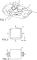
- FIG. 1 illustrates cut orientation 12 obtained when a GT-cut crystal plate is cut out from a single crystal quartz, i.e., raw stone 11.
- FIG. 1 also illustrates cut orientations of typical cuts other than the GT-cut.
- axes obtained by allowing the X-axis, the Y-axis, and the Z-axis to rotate around the X-axis by +51.5° are respectively defined as an X'-axis, a Y'-axis, and a Z'-axis.
- the X'-axis is obtained by allowing the X-axis to rotate about the X-axis, the X'-axis is identical with the X-axis.
- Axes obtained by allowing the X'-axis and the Z'-axis to rotate around the Y'-axis by 45° in the direction from the Z'-axis to the X'-axis are respectively defined as an X"-axis and a Z"-axis.
- a vibration mode in GT-cut crystal plate 21 is a combined vibration mode of a longitudinal vibration mode in an X"-axis direction and a longitudinal vibration mode in a Z"-axis direction. Both of the longitudinal vibration modes in the X"-axis direction and the Z"-axis direction are a length-extensional vibration mode. Vibration modes obtained by combining these two longitudinal vibration modes are also called "a width-length extensional coupling vibration mode". In the figures, length-extensional vibration directions are indicated by arrows, and an outline displaced by vibration is indicated by dotted lines.
- the displaced outline is illustrated as an outline with a much larger displacement than an actual displacement in crystal plate 21, for convenience of illustration.
- the GT-cut crystal plate of the related art is formed in a rectangular shape or a square shape with one pair of sides in parallel with the X"-axis and the other pair of sides in parallel with the Z"-axis to use as a vibrating plate, i.e., a crystal blank, in the crystal resonator. Both principal surfaces of the crystal plate are provided with excitation electrodes for exciting the crystal plate serving as a vibrating plate.
- a technique in which a main portion of a vibrating plate i.e., a vibration part, and a support portion for supporting the vibration part are integrally formed from a plate-shaped member a quartz crystal by using photolithography technique (see, JP-9-246898A ; and Hirofumi Kawashima, Osamu Ochiai, Akihito Kudo, and Atsunobu Nakajima, "Miniaturized GT-Cut Quartz Resonators" The Horological Institute of Japan, Vol. 104, pp. 36-48, 1983 ).
- photolithography technique see, JP-9-246898A ; and Hirofumi Kawashima, Osamu Ochiai, Akihito Kudo, and Atsunobu Nakajima, "Miniaturized GT-Cut Quartz Resonators" The Horological Institute of Japan, Vol. 104, pp. 36-48, 1983 ).
- support portions 22 are connected to positions of middle points on a pair of opposed sides in the main portion of a rectangular shape in crystal plate 21 serving as a vibrating plate.
- the shape of each support portion 22 is designed by using a finite element method or the like so that a resonance frequency of the vibration part itself is substantially the same as a resonance frequency of the entire resonance system including support portions 22.
- the vibration mode of the quartz crystal plate is varied depending on the type of cut.
- the vibration mode is a thickness-shear vibration mode, and the resonance frequency is determined only by the thickness.
- the planar shape of the AT-cut crystal plate can be arbitrarily set.
- the planar shape may be a circular or elliptical shape.
- a crystal blank of the AT-cut may be supported at a position corresponding to a stationary point of a thickness-shear vibration.
- the vibration mode is the width-length extensional coupling vibration mode, which means that the resonance frequency changes depending on the planar shape and size of the width, length, and the like of the crystal blank, and vibrations in two vibration modes coupled together must be reliably generated. Therefore, it is impossible to arbitrarily set the planar shape and to arrange the support portion at an arbitrary position. In particular, there is generally no stationary point of a vibration displacement on an outer peripheral portion of a rectangular GT-cut crystal plate.
- the GT-cut crystal plate has an excellent frequency-temperature characteristic, and is suitable for constructing a crystal oscillator with high stability and high accuracy.
- the GT-cut crystal blank of the related art has a rectangular shape, and the support portions are connected to the middle points on a pair of opposed sides. Since the vibration mode of the GT-cut crystal plate is the width-length extensional coupling vibration mode, the crystal plate is vibrated and displaced at the connected positions of the support portions, and the provision of the support portions may thus hinder vibration of the crystal plate. Attempts have been made to design each support portion using a finite element method so as to be formed in a shape that has no adverse effect on the vibration of the crystal plate. However, it is difficult to manufacture such support portions, because each support portion has a complicated shape. Further, the size of the support portion itself cannot be ignored in comparison to the size of the main portion of the vibrating plate. Therefore, a variation in dimensions of each support portion greatly affects the vibration characteristics of the crystal plate, and inhibits miniaturization of the crystal resonator.
- a GT-cut crystal resonator includes: a crystal plate formed in an elliptical shape with a major axis and a minor axis respectively corresponding to vibration directions of two longitudinal vibration modes orthogonal to each other in a GT-cut; and a support portion that supports the crystal plate, the support portion being connected to a position on an outer periphery of the crystal plate where a minimum vibration displacement is obtained when the two longitudinal vibration modes are coupled.
- the GT-cut crystal plate which is conventionally formed in a rectangular shape, is formed in an elliptical shape in the present invention. As described later, in the GT-cut crystal plate of the elliptical shape, there are four points where a minimum vibration displacement is obtained on an outer peripheral portion of the crystal plate.
- the support portion for supporting the crystal plate is connected to each of such points. According to the present invention, it is possible to support a crystal plate at a substantial stationary position for a vibration displacement and use a support portion having a small and simple configuration without adverse effect on vibration characteristics. Thus, it is possible to obtain a crystal resonator having an excellent temperature characteristic and high stability.
- Such a GT-cut crystal resonator includes: a frame; a plurality of crystal plates having the same resonance frequency, each of the crystal plates being formed in an elliptical shape with a major axis and a minor axis respectively corresponding to vibration directions of two longitudinal vibration modes orthogonal to each other in a GT-cut; a pair of excitation electrodes respectively formed on both principle surfaces of each of the crystal plates; and a support portion provided for each of the crystal plates, the support portion supporting a corresponding crystal plate on the frame and being connected to a position on an outer periphery of the corresponding crystal plate where a minimum vibration displacement is obtained when the two longitudinal vibration modes are coupled, wherein the plurality of crystal plates are arranged in the same plane including vibration directions of the two longitudinal vibration modes, an outer periphery of one crystal plate of adjacent two of the crystal plates is mechanically coupled to an outer periphery of the other crystal plate of the
- the quartz crystal resonator according to the first embodiment shown in FIG. 4 is identical with the crystal resonator of the related art described above in that GT-cut crystal plate 31 is used, but is different from the crystal resonator of the related art in that crystal plate 31 has an elliptic planar shape.
- Elliptical crystal plate 31 has a configuration in which the plate surface is orthogonal to a Y'-axis in a GT-cut; the major axis of the ellipse coincides with an X"-axis in the GT-cut; and the minor axis of the ellipse coincides with a Z"-axis.
- crystal plate 31 has, as a vibration mode, a width-length extensional coupling vibration mode which is a coupling of a longitudinal vibration mode in an X"-axis direction and a longitudinal vibration mode in a Z"-axis direction and which allows alternate expansion and contraction in the X"-axis direction and the Z"-axis direction, as with crystal plate 21 illustrated in FIG. 2 .
- the outline of crystal plate 31 displaced by vibration is emphasized by dotted lines.
- the magnitude of a vibration displacement is not constant at each point on the outer periphery.
- the magnitude of the vibration displacement is minimum. Since elliptical crystal plate 31 alternately expands and contracts in the X"-axis direction serving as the major axis and the Z"-axis direction serving as the minor axis, there are always four points where a minimum vibration displacement is obtained on the outer periphery of crystal plate 31, i.e., on the ellipse.
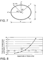
- points P 1 to P 4 are actual stationary points for the vibration displacement in the width-length extensional coupling vibration mode. Positions corresponding to the stationary points on the outer periphery of crystal plate 31 formed in an elliptical shape are varied depending on a ratio between length "a" of the major axis and length "b" of the minor axis of crystal plate 31. This ratio is an aspect ratio ( b / a ).
- each stationary point is positioned in a direction in which an angle of 57.5° is formed from the major axis direction toward the minor axis direction when viewed from the center of crystal plate 31, i.e., the center of the ellipse.
- each support portion can be formed by a simple rod-shaped member or a beam member connected to the outer periphery of crystal plate 31.
- FIGS. 5 and 6 illustrate an example of a specific configuration of the crystal resonator according to this embodiment thus configured.
- This crystal resonator includes frame 33 formed in a substantially rectangular shape, and holds elliptical GT-cut crystal plate 31 in an opening of frame 33.
- elliptical crystal plate 31 has a plate surface orthogonal to the Y'-axis in the GT-cut. The major axis of the ellipse coincides with the X"-axis in the GT-cut, and the minor axis of the ellipse coincides with the Z"-axis.
- Crystal plate 31 is supported by two rod-shaped support portions 32 extending from the inner wall of frame 33.
- Two support portions 32 are mechanically connected to crystal plate 31 at two stationary points of above-mentioned four stationary points P 1 to P 4 located on the outer periphery of elliptical crystal plate 31.
- support portions 32 are connected to a pair of stationary points P 2 and P 4 (see FIG. 4 ) sandwiching the center of crystal plate 31, i.e., the center of the ellipse.
- the thickness of frame 33 is sufficiently greater than the thickness of crystal plate 31.
- Such a crystal resonator can be formed such that, for example, a plate-shaped member of quartz corresponding to a GT-cut is used and photolithography technology is applied to the plate-shaped member so that portions corresponding to crystal plate 31, support portions 32, and frame 33 are left and the other portions are removed.
- the crystal resonator is formed by application of photolithography technology to the plate-shaped member of quartz, support portions 32 and frame 33 are formed of quartz and are integrally formed with crystal plate 31.
- excitation electrode 34 is formed on substantially the entire area of one principal surface of crystal plate 31, and extending electrode 36 for implementing electrical connection with excitation electrode 34 is formed on the surface of one support portion 32 and extends from excitation electrode 34 to connection pad 37 formed on the upper surface of frame 33.
- excitation electrode 35 is also formed on substantially the entire area of the other principal surface of crystal plate 31. Excitation electrode 35 is electrically connected to a connection pad (not shown), which is formed on the lower surface of frame 33, through an extending electrode (not shown) formed on the surface of the other support portion.
- crystal plate 31 is supported at two points.
- the number of support points and positions of stationary points where crystal plate 31 is supported can be arbitrarily determined, as long as crystal plate 31 is supported at stationary points P 1 to P 4 described above.
- FIG. 7 illustrates crystallographic orientations of axes in elliptical GT-cut crystal plate 31.
- elastic coefficient C' 11 in the X"-axis direction and elastic coefficient C' 33 in the Z"-axis direction are equal to each other, and thus the same vibration characteristics are presented even when the dimensions in the X"-axis direction are replaced with the dimensions in the Z"-axis direction. That is, in the above description, the major axis corresponds to the X"-axis direction and the minor axis corresponds to the Z"-axis direction in the elliptical crystal plate. Alternatively, even when the major axis corresponds to the Z"-axis direction and the minor axis corresponds to the X"-axis direction, the same effects as those described above can be obtained.
- FIG. 8 is a graph showing results obtained by examining a relation between the aspect ratio and a first-order temperature coefficient ⁇ . It is obvious that an excellent temperature characteristic can be obtained as long as the aspect ratio falls within the range of 0.75 to 0.90.
- the excellent temperature characteristic herein described indicates that the first-order temperature coefficient falls within the range of approximately ⁇ 10 ppm/°C.
- a crystal resonator including:
- a GT-cut crystal resonator has characteristics that equivalent series capacitance C1 becomes small and equivalent series resistance ESR becomes large, for example 1 k ⁇ , even if the excitation electrodes are formed as large as possible with respect to the plate surfaces of the crystal plate.
- equivalent series capacitance C1 is approximately one third of that of the AT-cut crystal plate and equivalent series resistance ESR is approximately three times as large as that of an AT-cut crystal plate.
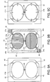
- the GT-cut crystal resonator according to the second embodiment shown in FIGS. 9A to 9C has two pieces of GT-cut crystal plates 41 a and 41 b each having a elliptical shape, each of which is similar to one shown in FIG. 4 .
- the crystal resonator has a configuration in which crystal plates 41 a and 41 b are held in an opening of frame 43.
- the directions of a minor axis and a major axis of each of crystal plates 41 a and 41 b coincide with vibration directions of two longitudinal vibration modes in a quartz crystal of the GT-cut, respectively.
- the vibration directions are orthogonal to each other.
- the outer shapes of crystal plates 41 a and 41 b are identical to each other, and both crystal plates 41 a and 41 b have thus an identical resonance frequency in the vibration mode of the GT-cut.
- Each of crystal plates 41 a and 41 b is supported by two rod-shaped support portions 42 extending from the inner wall of frame 43.
- Two support portions 42 for each crystal plate are mechanically connected to the corresponding crystal plate at two stationary points of above-mentioned four stationary points P 1 to P 4 located on the outer periphery of the elliptical crystal plate.
- the thickness of frame 43 is sufficiently greater than the thickness of crystal plates 41 a and 41 b.
- Crystal plates 41 a and 41 b are disposed such that the minor axes of them are arranged along a straight line. Crystal plates 41 a and 41 b are mechanically coupled to each other by rod-shaped connection member 48.
- connection member 48 is connected to a point on the outer periphery of crystal plate 41 a and to a point on the outer periphery of crystal plate 41 b.
- one end of the minor axis of crystal plate 41 a and one end of the minor axis of crystal plate 41 b are connected to each other by connection member 48.
- connection member 48 it is possible to arrange crystal plates 41 a and 41 b such that the major axes of them are arranged along a straight line and connect one end of the major axis of crystal plate 41 a with one end of the major axis of crystal plate 41 b. It is not necessary to set the connection position of connection member 48 to the one end of the major or minor axis of the crystal plate. However, if the connection member is connected to the above-described stationary point on the periphery of the crystal plate, the significance of providing the connection member would be lost and both crystal plates would not be mechanically coupled.
- Crystal plates 41 a and 41 b, support portions 42, frame 43 and connection member 48 are integrally formed by quartz.
- two crystal plates 41 a and 41 b are arranged within a plane formed by the vibration directions of the two longitudinal vibration modes of a GT-cut quartz crystal, and support portions 42 and connection member 48 are also arranged within the plane.
- excitation electrode 44 is formed on substantially the entire area of each of two principal surfaces of each of crystal plates 41 a and 41 b.
- Excitation electrode 44 formed on the top surface of crystal plate 41 a is electrically connected to the excitation electrode formed on the back surface of crystal plate 41 b through conduction path 45a which is formed on the top surface of support potion 42 and frame 43.
- Electrode pad 47a for connecting this crystal resonator to an external circuit is also arranged in this conduction path 45a.
- the excitation electrode formed on the back surface of crystal plate 41 a is electrically connected to excitation electrode 44 formed on the top surface of crystal plate 41 b through conduction path 45b which is formed on support portion 42 and frame 43.
- Electrode pad 47b for connection to the external circuit is arranged in conduction path 45b. Electrode pads 47a and 47b are formed on the top surface of frame 43. Through-holes 46 passing through frame 43 are arranged in conduction paths 45a and 45b because of necessity of electrically connecting the excitation electrode on the top surface with the excitation electrode on the back surface.
- connection member 48 mechanically couples both crystal plates 41 a and 41 while it does not disturb vibration of the crystal plates.
- connection member 48 since connection member 48 is provided, both crystal plates 41 a and 41 b integrally resonate at the same frequency and a high Q (quality factor) value as a crystal resonator can be obtained even in a situation where inherent resonance frequencies of those crystal plates are somewhat different from each other. If connection member 48 is not provided, the situation is electrically equivalent to a case where two crystal resonators having slight different resonance frequencies are connected in parallel and this causes reduction in the Q value as a whole.
- each of crystal plates 41 a and 41 b is supported by support portions 42 at the points on an outer periphery of the crystal plate where a minimum vibration displacement is obtained, support portions 42 do not affect the vibration characteristics of crystal plates 41 a and 41 b.
- Connection member 48 mechanically couples both crystal plates 41 a and 41 while it does not disturb vibration of the crystal plates. Since crystal plates 41 a and 41 b have the same resonance frequency, crystal plates 41 a and 41 b oscillate at this common resonance frequency. In addition, crystal plates 41 a and 41 b vibrate with stability in a single vibration mode which is coupled across both crystal plates, as a whole crystal resonator. As a result, this crystal resonator vibrates with very high stability without generating a spurious vibration.
- the area of excitation electrodes becomes twice as large as that of the crystal resonator shown in FIG. 4 while the resonance frequency is unchanged. Therefore, the equivalent series capacitance doubles and the equivalent series resistance is reduced by half when comparing to the crystal resonator shown in FIG. 4 .
- the GT-cut crystal resonator of the present embodiment is applied to an oscillator circuit, it is possible to obtain a large oscillation margin with a simple circuit configuration and construct an oscillation circuit with high stability because of smaller equivalent series resistance.
- one end of the minor axis of crystal plate 41a is mechanically coupled to one end of the minor axis of crystal plate 41 b.
- elastic coefficient C' 11 in the X"-axis direction and elastic coefficient C' 33 in the Z"-axis direction are equal to each other, and thus the same effects as those described above can be obtained in a case where one end of the major axis of one crystal plate is mechanically coupled to one end of the major axis of the other crystal plate.
- Two crystal plates 41 a and 41 b are used to constitute a crystal resonator in the second embodiment.
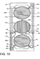
- the crystal resonator according to the third embodiment shown in FIG. 10 is similar to that shown in FIGS. 9A to 9C except that three crystal plates 41 a to 41 c are provided.
- Each of crystal plates 41 a to 41 c is connected to frame 43 by two rod-shaped support portions 42 which are provided for each crystal plate.
- Support portions 42 are connected to the corresponding crystal plate at the positions on an outer periphery of the crystal plate where a minimum vibration displacement is obtained.
- Crystal plates 41 a and 41 b are mechanically coupled to each other, and crystal plates 41 b and 41 c are also mechanically coupled to each other.
- Excitation electrode 44 is formed on each of two principal surfaces of each of crystal plates 41 a to 41 c.
- the excitation electrodes formed on the top surfaces of crystal plates 41 a and 41 and the excitation electrode formed on the back surface of crystal plate 41 b are electrically connected to each other through conduction path 45a.
- Electrode pad 47a is also arranged in conduction path 45a.
- the excitation electrodes formed on the back surfaces of crystal plates 41 a and 41 and the excitation electrode formed on the top surface of crystal plate 41 b are electrically connected to each other through conduction path 45b.
- Electrode pad 47b is also arranged in conduction path 45b.
- connection members 48a and 48b mechanically couple crystal plates 41 a to 41 c while they do not disturb vibration of the crystal plates.
- crystal plates 41 a to 41 c oscillate at the common resonance frequency, and vibrate with stability in a single vibration mode which is coupled across crystal plates 41 a to 41 c, as a whole crystal resonator.
- the area of excitation electrodes becomes three times as large as that of the crystal resonator shown in FIG. 4 while the resonance frequency is unchanged. Therefore, the equivalent series capacitance triples and the equivalent series resistance is reduced by one third when comparing to the crystal resonator shown in FIG. 4 .
- the GT-cut crystal resonator of the present embodiment is applied to an oscillator circuit, it is possible to obtain a large oscillation margin with a simple circuit configuration and construct an oscillation circuit with high stability.
- connection member 48 is arranged between adjacent crystal plates 41 a and 41 b to mechanically couple these crystal plates 41 a and 41 b.
- the manner of mechanical coupling between crystal plates is not limited to this.
- the crystal resonator according to the fourth embodiment as shown in FIG. 11 is similar to that of the second embodiment except that mechanical coupling between the crystal plates 41 a and 41 b is realized by directly joining one end of the minor axis of crystal plate 41 a and one end of the minor axis of crystal plate 41 b without arranging a connection member.
- crystal plates 41 a and 41 b are electrically excited in reverse polarities to each other as described above, no stress occurs at a joining location between crystal plates 41 a and 41 b when the crystal plates are directly joined.
- the crystal resonator according to the present embodiment has the similar advantageous effect as that of the second embodiment.
- a plurality of GT-cut crystal plates having the same resonance frequency are arranged, outer peripheries of adjacent two crystal plates are mechanically coupled to each other, and electric wirings are formed among the excitation electrodes so that, when one crystal plate of the two adjacent crystal plates expands in a first direction, the other crystal plate expands in a second direction which is orthogonal to the first direction.
- the plurality of the crystal plates are electrically connected in parallel with each other. Therefore, the equivalent series capacitance of the crystal resonator is increased and the equivalent series resistance is reduced as a whole in comparison to a crystal resonator including only one crystal plate.
- the crystal resonator according to one of the second to fourth embodiment has, for example, equivalent series resistance which is equivalent to that of an AT-cut crystal resonator.
- the crystal plates are coupled to a single vibration mode as a whole by mechanically coupling the crystal plates and electrically connecting the excitation electrodes in the manner described above.
- the crystal resonator shows very high stability without generating a spurious vibration.
- each of elliptical crystal plates 41 a to 41 c it is preferable to set the aspect ratio ( b / a ) of each of elliptical crystal plates 41 a to 41 c within the range of 0.75 to 0.90 in the crystal resonator according to one of the second to fourth embodiments.
Landscapes
- Physics & Mathematics (AREA)
- Acoustics & Sound (AREA)
- Piezo-Electric Or Mechanical Vibrators, Or Delay Or Filter Circuits (AREA)
Applications Claiming Priority (2)
| Application Number | Priority Date | Filing Date | Title |
|---|---|---|---|
| JP2011037086A JP5661506B2 (ja) | 2011-02-23 | 2011-02-23 | 水晶振動子 |
| JP2011244672A JP5789485B2 (ja) | 2011-11-08 | 2011-11-08 | 水晶振動子 |
Publications (2)
| Publication Number | Publication Date |
|---|---|
| EP2493072A2 true EP2493072A2 (fr) | 2012-08-29 |
| EP2493072A3 EP2493072A3 (fr) | 2015-04-08 |
Family
ID=45656357
Family Applications (1)
| Application Number | Title | Priority Date | Filing Date |
|---|---|---|---|
| EP12156438.9A Withdrawn EP2493072A3 (fr) | 2011-02-23 | 2012-02-22 | Résonateur à cristal de quartz coupé GT |
Country Status (4)
| Country | Link |
|---|---|
| US (1) | US8957569B2 (fr) |
| EP (1) | EP2493072A3 (fr) |
| CN (1) | CN102655400A (fr) |
| TW (1) | TW201238244A (fr) |
Families Citing this family (8)
| Publication number | Priority date | Publication date | Assignee | Title |
|---|---|---|---|---|
| JP6295611B2 (ja) * | 2013-11-05 | 2018-03-20 | セイコーエプソン株式会社 | 振動子、発振器、電子機器、および移動体 |
| JP6338367B2 (ja) * | 2013-12-24 | 2018-06-06 | 日本電波工業株式会社 | 水晶振動子 |
| JP2017158146A (ja) * | 2016-03-04 | 2017-09-07 | 日本電波工業株式会社 | 水晶振動子 |
| JP6755108B2 (ja) * | 2016-03-23 | 2020-09-16 | 日本電波工業株式会社 | 水晶振動子 |
| JP2017192032A (ja) * | 2016-04-13 | 2017-10-19 | 日本電波工業株式会社 | 水晶振動子 |
| CN106982042B (zh) * | 2017-03-20 | 2020-06-16 | 电子科技大学 | 一种支撑结构的mems压电谐振器 |
| JP6797764B2 (ja) * | 2017-08-09 | 2020-12-09 | 日本電波工業株式会社 | 水晶振動子およびその製造方法 |
| WO2020255520A1 (fr) * | 2019-06-17 | 2020-12-24 | 株式会社村田製作所 | Résonateur et dispositif de résonance |
Citations (2)
| Publication number | Priority date | Publication date | Assignee | Title |
|---|---|---|---|---|
| JPH09246898A (ja) | 1996-03-05 | 1997-09-19 | S I I Quartz Techno:Kk | 水晶振動子の製造方法 |
| JP2007158486A (ja) | 2005-12-01 | 2007-06-21 | Epson Toyocom Corp | 水晶振動素子、水晶振動子、及び水晶発振器 |
Family Cites Families (10)
| Publication number | Priority date | Publication date | Assignee | Title |
|---|---|---|---|---|
| JPH03150911A (ja) | 1989-11-07 | 1991-06-27 | Seiko Electronic Components Ltd | 高調波結合振動子 |
| CH683050A5 (fr) * | 1991-06-04 | 1993-12-31 | Suisse Electronique Microtech | Résonateur à quartz vibrant selon un mode fondamental de torsion. |
| US5323083A (en) * | 1991-10-25 | 1994-06-21 | Piezo Technology, Inc. | Crystal resonator having reduced acceleration sensitivity |
| JP2001313537A (ja) | 2000-04-28 | 2001-11-09 | River Eletec Kk | 圧電素子とその製造方法 |
| JP3743913B2 (ja) | 2002-09-19 | 2006-02-08 | 有限会社ピエデック技術研究所 | 水晶振動子、水晶ユニット、水晶発振器とそれらの製造方法 |
| JP2006311303A (ja) * | 2005-04-28 | 2006-11-09 | River Eletec Kk | モード結合型圧電振動子 |
| US7834526B2 (en) * | 2007-04-10 | 2010-11-16 | Seiko Epson Corporation | Contour resonator |
| CN101847975B (zh) * | 2010-03-31 | 2012-08-08 | 山东大学 | NdCa4O(BO3)3晶体零频率温度系数切型及应用 |
| FI124453B (fi) * | 2010-08-13 | 2014-09-15 | Valtion Teknillinen | Mikromekaaninen resonaattorijärjestelmä ja menetelmä sen valmistamiseksi |
| JP2013081022A (ja) * | 2011-10-03 | 2013-05-02 | Nippon Dempa Kogyo Co Ltd | 水晶振動子及びその製造方法 |
-
2012
- 2012-02-09 TW TW101104240A patent/TW201238244A/zh unknown
- 2012-02-13 US US13/372,373 patent/US8957569B2/en not_active Expired - Fee Related
- 2012-02-22 EP EP12156438.9A patent/EP2493072A3/fr not_active Withdrawn
- 2012-02-22 CN CN2012100427332A patent/CN102655400A/zh active Pending
Patent Citations (2)
| Publication number | Priority date | Publication date | Assignee | Title |
|---|---|---|---|---|
| JPH09246898A (ja) | 1996-03-05 | 1997-09-19 | S I I Quartz Techno:Kk | 水晶振動子の製造方法 |
| JP2007158486A (ja) | 2005-12-01 | 2007-06-21 | Epson Toyocom Corp | 水晶振動素子、水晶振動子、及び水晶発振器 |
Non-Patent Citations (2)
| Title |
|---|
| HIROFUMI KAWASHIMA; KOICHI HIRAMA; NAOYA SAITO; MITSUAKI KOYAMA: "Quartz Resonators and Devices", TRANSACTIONS OF THE INSTITUTE OF ELECTRONICS, INFORMATION AND COMMUNICATION ENGINEERS C-1, vol. J82-C-I, no. 12, December 1999 (1999-12-01) |
| HIROFUMI KAWASHIMA; OSAMU OCHIAI; AKIHITO KUDO; ATSUNOBU NAKAJIMA: "Miniaturized GT-Cut Quartz Resonators", THE HOROLOGICAL INSTITUTE OF JAPAN, vol. 104, 1983, pages 36 - 48 |
Also Published As
| Publication number | Publication date |
|---|---|
| CN102655400A (zh) | 2012-09-05 |
| TW201238244A (en) | 2012-09-16 |
| US20120212107A1 (en) | 2012-08-23 |
| EP2493072A3 (fr) | 2015-04-08 |
| US8957569B2 (en) | 2015-02-17 |
Similar Documents
| Publication | Publication Date | Title |
|---|---|---|
| US8957569B2 (en) | GT-cut quartz crystal resonator | |
| KR101219211B1 (ko) | 진동편, 진동자, 발진기, 전자기기, 및 주파수 조정 방법 | |
| JP2004200917A (ja) | 圧電振動片と圧電振動片を利用した圧電デバイス、ならびに圧電デバイスを利用した携帯電話装置および圧電デバイスを利用した電子機器 | |
| JP6338367B2 (ja) | 水晶振動子 | |
| JP7453147B2 (ja) | Mems共振器の構成 | |
| JP2009200706A (ja) | 振動片、振動子及び発振器 | |
| CN102064793A (zh) | 振动器件及电子设备 | |
| JP2006203304A (ja) | 圧電薄膜共振器及びそれを用いた発振器並びにそれを内蔵した半導体集積回路 | |
| JP5668392B2 (ja) | 圧電振動素子、圧電振動子及び圧電発振器 | |
| US9318998B1 (en) | Acoustically-engineered multi-port piezoelectric-on-semiconductor resonators for accurate temperature sensing and reference signal generation | |
| JP2002158559A (ja) | ラーメモード水晶振動子 | |
| JP2002111434A (ja) | ラーメ振動水晶振動子 | |
| JP2011191091A (ja) | 音叉型振動片、振動子およびセンサー装置 | |
| JP5789485B2 (ja) | 水晶振動子 | |
| CN1914799B (zh) | 音叉型振动片、压电振子、角速度传感器、以及电子设备 | |
| JPS58220515A (ja) | 伸長モ−ド圧電形マイクロ共振器 | |
| JP5661506B2 (ja) | 水晶振動子 | |
| JPS6316169Y2 (fr) | ||
| US20140210566A1 (en) | Crystal resonator, crystal resonator package, and crystal oscillator | |
| CN116429281A (zh) | 基于阵列结构的谐振器以及测温方法 | |
| JP2005026843A (ja) | 圧電デバイス | |
| JP2011199454A (ja) | 振動体および振動デバイス | |
| JP2010048643A (ja) | 加速度検知ユニット、及び加速度センサ | |
| JP2003273703A (ja) | 水晶振動子と水晶振動子の製造方法 | |
| JP2014030111A (ja) | 水晶フィルタ |
Legal Events
| Date | Code | Title | Description |
|---|---|---|---|
| PUAI | Public reference made under article 153(3) epc to a published international application that has entered the european phase |
Free format text: ORIGINAL CODE: 0009012 |
|
| AK | Designated contracting states |
Kind code of ref document: A2 Designated state(s): AL AT BE BG CH CY CZ DE DK EE ES FI FR GB GR HR HU IE IS IT LI LT LU LV MC MK MT NL NO PL PT RO RS SE SI SK SM TR |
|
| AX | Request for extension of the european patent |
Extension state: BA ME |
|
| PUAL | Search report despatched |
Free format text: ORIGINAL CODE: 0009013 |
|
| AK | Designated contracting states |
Kind code of ref document: A3 Designated state(s): AL AT BE BG CH CY CZ DE DK EE ES FI FR GB GR HR HU IE IS IT LI LT LU LV MC MK MT NL NO PL PT RO RS SE SI SK SM TR |
|
| AX | Request for extension of the european patent |
Extension state: BA ME |
|
| RIC1 | Information provided on ipc code assigned before grant |
Ipc: H03H 9/205 20060101ALI20150304BHEP Ipc: H03H 9/02 20060101AFI20150304BHEP Ipc: H03H 9/24 20060101ALN20150304BHEP Ipc: H03H 9/05 20060101ALI20150304BHEP Ipc: H03H 9/13 20060101ALI20150304BHEP |
|
| STAA | Information on the status of an ep patent application or granted ep patent |
Free format text: STATUS: THE APPLICATION IS DEEMED TO BE WITHDRAWN |
|
| 18D | Application deemed to be withdrawn |
Effective date: 20151009 |