EP2493544B1 - Garniture de cathéter stérile scellée - Google Patents
Garniture de cathéter stérile scellée Download PDFInfo
- Publication number
- EP2493544B1 EP2493544B1 EP10830440.3A EP10830440A EP2493544B1 EP 2493544 B1 EP2493544 B1 EP 2493544B1 EP 10830440 A EP10830440 A EP 10830440A EP 2493544 B1 EP2493544 B1 EP 2493544B1
- Authority
- EP
- European Patent Office
- Prior art keywords
- catheter
- dressing
- sheath
- patient
- plate
- Prior art date
- Legal status (The legal status is an assumption and is not a legal conclusion. Google has not performed a legal analysis and makes no representation as to the accuracy of the status listed.)
- Active
Links
Images












Classifications
-
- A—HUMAN NECESSITIES
- A61—MEDICAL OR VETERINARY SCIENCE; HYGIENE
- A61M—DEVICES FOR INTRODUCING MEDIA INTO, OR ONTO, THE BODY; DEVICES FOR TRANSDUCING BODY MEDIA OR FOR TAKING MEDIA FROM THE BODY; DEVICES FOR PRODUCING OR ENDING SLEEP OR STUPOR
- A61M25/00—Catheters; Hollow probes
- A61M25/01—Introducing, guiding, advancing, emplacing or holding catheters
- A61M25/02—Holding devices, e.g. on the body
-
- A—HUMAN NECESSITIES
- A61—MEDICAL OR VETERINARY SCIENCE; HYGIENE
- A61M—DEVICES FOR INTRODUCING MEDIA INTO, OR ONTO, THE BODY; DEVICES FOR TRANSDUCING BODY MEDIA OR FOR TAKING MEDIA FROM THE BODY; DEVICES FOR PRODUCING OR ENDING SLEEP OR STUPOR
- A61M25/00—Catheters; Hollow probes
- A61M25/01—Introducing, guiding, advancing, emplacing or holding catheters
-
- A—HUMAN NECESSITIES
- A61—MEDICAL OR VETERINARY SCIENCE; HYGIENE
- A61M—DEVICES FOR INTRODUCING MEDIA INTO, OR ONTO, THE BODY; DEVICES FOR TRANSDUCING BODY MEDIA OR FOR TAKING MEDIA FROM THE BODY; DEVICES FOR PRODUCING OR ENDING SLEEP OR STUPOR
- A61M39/00—Tubes, tube connectors, tube couplings, valves, access sites or the like, specially adapted for medical use
- A61M39/10—Tube connectors; Tube couplings
-
- A—HUMAN NECESSITIES
- A61—MEDICAL OR VETERINARY SCIENCE; HYGIENE
- A61M—DEVICES FOR INTRODUCING MEDIA INTO, OR ONTO, THE BODY; DEVICES FOR TRANSDUCING BODY MEDIA OR FOR TAKING MEDIA FROM THE BODY; DEVICES FOR PRODUCING OR ENDING SLEEP OR STUPOR
- A61M25/00—Catheters; Hollow probes
- A61M25/01—Introducing, guiding, advancing, emplacing or holding catheters
- A61M25/02—Holding devices, e.g. on the body
- A61M2025/0253—Holding devices, e.g. on the body where the catheter is attached by straps, bands or the like secured by adhesives
-
- A—HUMAN NECESSITIES
- A61—MEDICAL OR VETERINARY SCIENCE; HYGIENE
- A61M—DEVICES FOR INTRODUCING MEDIA INTO, OR ONTO, THE BODY; DEVICES FOR TRANSDUCING BODY MEDIA OR FOR TAKING MEDIA FROM THE BODY; DEVICES FOR PRODUCING OR ENDING SLEEP OR STUPOR
- A61M25/00—Catheters; Hollow probes
- A61M25/01—Introducing, guiding, advancing, emplacing or holding catheters
- A61M25/0105—Steering means as part of the catheter or advancing means; Markers for positioning
- A61M25/0111—Aseptic insertion devices
Definitions
- the present invention relates to devices for sealing medical devices, and in particular to methods and devices for sealing and maintaining sterility at a catheter insertion site.
- a catheter into a body cavity, duct, or vessel to allow drainage, injection of fluids, and/or access by surgical instruments is a common procedure in the practice of medicine.
- Catheters come in a variety of shapes and forms and can be used for a variety of tasks, including chemotherapy, fluid drainage, hemodialysis, and administering intravenous fluids, anesthesia, or other medications.
- a peripheral intravascular catheter can be used to administer medication, nutrition, and various other intravenous fluids via peripheral blood vessels, to perform hemodynamic measurements, and to provide access for procedures and devices affecting the cardiovascular system.
- a central venous catheter can be used to deliver medications or fluids to vessels near the heart or into the heart itself.
- peripheral venous catheters and more than 250,000 central venous catheters are placed in patients in the United States each year.
- Other intravascular catheters include those used for hemodialysis, peripheral central access (PIC), interventional procedure access, cardiac ventricular assist device access, and other long term vascular access support. These can be both arterial and venous in respect to the type of vessel in which they are inserted.
- the catheter insertion site is traditionally and universally dressed by pressing the round, tubular catheter against the skin of the patient with a sterile adhesive patch-type dressing or with sterile gauze and adhesive tape, which are the two dressing types recommended by the United States Centers for Disease Control and Prevention ("CDC").
- CDC United States Centers for Disease Control and Prevention
- US 4,767,411 discloses a protective catheter sleeve for use with indwelling catheters, wires and the like, such as during long-term patient care.
- the protective catheter sleeve includes a surrounding flexible side wall, the upper end of which is adhesively secured about the catheter and the lower end of which is adhesively secured about the puncture site on the patient skin, to define a sealed chamber therein.
- WO 2008/117078 discloses a dressing for supporting a tube in an incision in a body.
- the dressing comprises a base arranged to be located to support the tube in position.
- catheter dressing methods and devices that provide for improved sealing at the catheter-dressing junction and/or improved sterility at the catheter insertion site.
- the devices and methods disclosed herein represent a paradigm shift in intravascular catheter care from a non-sterile, non-sealing dressing to a fully sealed and durably-sterile solution.
- Methods and devices are disclosed for dressing and/or sealing a catheter insertion site.
- a catheter dressing can include an adhesive plate configured for attachment to the skin of a patient and a flexible sheath having a proximal end and a distal end and extending proximally from the adhesive plate.
- the sheath is capable of longitudinal extension from a compressed to an extended state and configured in its extended state to surround an external segment of a catheter implanted in the patient and circumferentially seal to a portion of the external segment at a distance from the adhesive plate.
- the sheath can define a sealed chamber around the external segment of the catheter and a portion of the patient. In one embodiment, movement of the catheter with respect to the patient does not disrupt a seal fonned between the sheath and the catheter.
- the sheath can optionally be coupled to the catheter.
- the sheath can include a splittable seam formed therein and can be capable of being opened along the seam such that the catheter dressing can be removed from a catheter around which the dressing is installed.
- the seam can include a non-full-thickness perforation.
- the sheath can include an attachment mechanism, such as a friction coupler, a threaded coupler, an inflation coupler, an electromagnetic coupler, and/or an adhesive.
- the attachment mechanism can be attached to the adhesive plate.
- the sheath can also include a stretchable gasket ring at its proximal end for sealing to the portion of the external segment of the catheter and the portion of the external segment of the catheter can include an annular groove for receiving the stretchable gasket ring.
- At least a portion of the sheath can include an access portal and/or an absorbent member disposed therein.
- the sealed chamber can be sterile.
- the sheath can be formed integrally with the catheter.
- the external segment of the catheter can include one or more of a catheter body, a catheter hub, a MicroCLAVE-type needleless connector, and/or a Luer-type connector.
- the sheath can be formed of at least one of an antibiotic-impregnated material and an antimicrobial-impregnated material and/or at least one of an antibiotic secreting member and an antimicrobial secreting member can be disposed within the sheath.
- the catheter dressing can include a clamp configured to secure at least one of the sheath and the external segment of the catheter to the patient.
- the clamp can also be configured to apply a compressive force to the gasket ring of the sheath and/or to increase the integrity of a seal formed between the sheath and the external segment of the catheter.
- the dressing can include a coupling member configured for coupling to a terminal end of the external segment of the catheter, the coupling member having at least one lumen to provide a fluid flow path to or from the catheter.
- the sheath can be extendable between the adhesive plate and the coupling member to surround a longitudinal segment of the catheter.
- the sheath is configured to restrict longitudinal movement of the external segment of the catheter relative to the patient while permitting non-longitudinal movement of the external segment of the catheter relative to the patient.
- the sheath can also be formed integrally with the coupling member, and/or the coupling member can be directly attached to the adhesive plate.
- the coupling member can be any of a valve, a catheter body, a catheter hub, a Luer-type connector, a MicroCLAVE-type connector, a threaded fitting, and/or a friction fitting.
- a kit is provided that includes the catheter dressing and a catheter having a mating feature for attachment of the catheter to the catheter dressing.
- a catheter dressing assembly can include an adhesive plate configured for attachment to the skin of a patient, a coupling member configured for coupling to an external end of a catheter implanted in the patient, the coupling member having at least one lumen to provide a fluid flow path to or from the catheter, and a flexible sheath extendable between the adhesive plate and the coupling member to surround a longitudinal segment of the catheter.
- the sheath can include an attachment mechanism for attaching the sheath to the coupling member, such as a friction coupler, a threaded coupler, an inflation coupler, an electromagnetic coupler, and/or an adhesive.
- the attachment mechanism can be attached to the adhesive plate.
- the sheath can also include a stretchable gasket ring at its proximal end for sealing to the coupling member and the coupling member can include an annular groove for receiving the stretchable gasket ring. At least a portion of the sheath can be transparent and the sheath can include an access portal.
- the dressing assembly can also include an absorbent member disposed within the sheath.
- the sheath can define a sealed chamber around the end of the catheter and a portion of the patient. In one embodiment, the sealed chamber can be sterile.
- the sheath can be formed integrally with the coupling member and/or the coupling member can be directly attached to the adhesive plate. In such embodiments, movement of the catheter with respect to the patient does not disrupt a seal formed between the sheath and the coupling member.
- the sheath can be formed of at least one of an antibiotic-impregnated material or an antimicrobial-impregnated material capable of secreting an antibiotic or antimicrobial agent.
- the dressing assembly can include a clamp configured to secure at least one of the sheath and the coupling member to the patient.
- the clamp can also be configured to apply a compressive force to the gasket ring of the sheath and/or to increase the integrity of a seal formed between the sheath and the external segment of the catheter.
- the coupling member can include a valve, a catheter body, a catheter hub, a Luer-type connector, a MicroCLAVE-type connector, a threaded fitting, and/or a friction fitting.
- a method for circumferentially sealing a catheter insertion site can include inserting a distal end of a catheter into a patient at an insertion site, connecting a proximal end of the catheter to a coupling member having a flexible sheath extendable therefrom, extending the sheath along an external segment of the catheter to the patient, and adhesively sealing a distal end of the sheath circumferentially around the catheter insertion site.
- the method can also include unsealing the distal end of the sheath and disconnecting the proximal end of the catheter from the coupling member.
- the method can further include moving the catheter with respect to the patient without disrupting a seal formed between the sheath and the catheter or coupling member.
- the method can also include effecting and maintaining a sterile seal around the insertion site and/or securing at least one of the sheath and the external segment of the catheter to the patient.
- the method can include moving the catheter with respect to the patient without disrupting a seal formed between the sheath and the coupling member, applying a sterilizing agent to an interior volume of the sheath through an access portal formed in a sidewall of the sheath, and/or applying sterilizing radiation to an internal volume of the sheath.
- the sterilizing agent can include at least one of an antibiotic solution, an antimicrobial solution, and a sterilization gas.
- the method can also include removing a sample from the internal volume of the sheath through an access portal formed in a sidewall of the sheath and testing the sample.
- the method can also include separating the dressing along a non-full-thickness perforation formed in a sidewall of the dressing.
- a method for circumferentially sealing a catheter insertion site.
- the method includes inserting a distal end of a catheter into a patient at an insertion site, the catheter having a flexible sheath extendable therefrom, extending the sheath along an external segment of the catheter to the patient, and sealing a distal end of the sheath circumferentially around the catheter insertion site.
- a catheter and dressing assembly in yet another aspect, includes a catheter and an integrated dressing comprising an adhesive plate and a flexible sheath having a proximal end joined to the catheter and a distal end joined to the adhesive plate.
- the sheath is capable of longitudinal extension from a compressed to an extended state and configured in its extended state to surround an external segment of the catheter when implanted in the patient and the adhesive plate is configured for attachment to the patient's skin to provide a circumferential seal.
- the sheath can also include a stretchable gasket ring at its proximal end for sealing to the portion of the external segment of the catheter.
- the sheath can also include an attachment mechanism, such as a friction coupler, a snap-fit coupler, a threaded coupler, an inflation coupler, an electromagnetic coupler, or an adhesive.
- the external segment of the catheter can be any of a catheter body, a catheter hub, a MicroCLAVE-type connector, and a Luer-type connector, and can include an annular groove for receiving the stretchable gasket ring.
- At least a portion of the sheath can be transparent, and an absorbent member can be disposed within the sheath.
- the sheath can define a sealed chamber around the external segment of the catheter and a portion of the patient and the sealed chamber can be sterile.
- the sheath can include an access portal and can be formed integrally with the catheter.
- the assembly can also include a clamp configured to secure at least one of the sheath and the external segment of the catheter to the patient. The clamp can be configured to increase the integrity of a seal formed between the sheath and the external segment of the catheter.
- the sheath can also include a stretchable gasket ring at its proximal end for sealing to the portion of the external segment of the catheter and the clamp can be configured to apply a compressive force to the gasket ring.
- the attachment mechanism is attached to the adhesive plate.
- a removable catheter dressing in another aspect, includes an adhesive plate configured for attachment to the skin of a patient and a flexible sheath having a proximal end and a distal end and extending proximally from the adhesive plate, the flexible sheath having a longitudinal seam formed therein.
- the sheath is capable of being opened along the seam such that the catheter dressing can be removed from a catheter around which the dressing is installed.
- the seam can be a non-full-thickness perforation.
- a method for removing a catheter dressing from a catheter that is at least partially inserted into a patient.
- the method includes separating the dressing from the tether, e.g., along a longitudinal non-full-thickness perforation formed in a sidewall of the dressing.
- a catheter dressing in another aspect, includes an adhesive plate configured for attachment to the skin of a patient and a flexible sheath having a proximal end and a distal end and extending proximally from the adhesive plate, the flexible sheath having a longitudinal opening formed therein.
- the sheath is capable of being placed around an installed catheter and closed along the opening to circumferentially seal an external portion of the installed catheter at a distance from the adhesive plate.
- the dressing can also include a mating mechanism configured to selectively mate first and second free edges of the sheath to one another along the opening.
- the mating mechanism can include any of a friction-based closure, an adhesive closure, a latch-type closure, and a male-female closure.
- a method for replacing a catheter dressing.
- the method includes removing a first catheter dressing circumferentially sealed around an external portion of a catheter that is at least partially inserted into a patient, placing a second catheter dressing having a longitudinal opening around the external portion of the catheter, and sealing the opening of the second catheter dressing to circumferentially seal the external portion of the catheter.
- the method can also include securing the external portion of the catheter to the patient with the second catheter dressing such that longitudinal movement of the external portion of the catheter relative to the patient is restricted and non-longitudinal movement of the external segment of the catheter relative to the patient is permitted.
- the method can also include at least one of sterilizing and cleaning a site at which the catheter is inserted into the patient after removing the first catheter dressing and before placing the second catheter dressing.
- sealing the opening includes joining first and second free edges of the second catheter dressing, which can optionally include mating at least one of a friction-based closure, an adhesive closure, a latch-type closure, and a male-female closure formed thereon.
- the method can also include clamping a sheath portion of the second catheter dressing to an exterior surface of a catheter hub with a circumferential support ring and/or reinforcing a seal between an adhesive plate portion of the second catheter dressing and a skin of the patient by applying a circular adhesive ring, the circular adhesive ring having an outer diameter that is greater than an outer diameter of the adhesive plate portion.
- a catheter dressing in another aspect, includes a unitary body having a planar distal adhesive surface defining a distal opening, a proximal portion defining a proximal opening, and an interior chamber extending from the proximal opening to the distal opening.
- the proximal opening is configured to form a circumferential seal around a catheter that is at least partially inserted into a patient and the distal adhesive surface is configured to adhere to the patient's skin to form a circumferential seal around a skin site at which the catheter is inserted.
- the body includes a splittable seam along which the body can be selectively opened and resealed.
- the body can be rigid or semi-rigid such that the body restricts movement of the catheter relative to the patient and the body can include an access portal.
- the proximal opening can be formed perpendicular to the planar distal adhesive surface.
- a catheter in yet another aspect, includes an elongate tubular body having proximal and distal ends and defining a central lumen.
- the body includes a mating feature for mating to a catheter dressing such that a sheath portion of the dressing can be coupled to the mating feature and extended towards a patient to create a circumferential sterile seal around an opening in the patient through which at least a portion of the body is inserted.
- the methods and devices can be used to achieve a sterile seal when placing a catheter using a Seldinger technique.
- the dressing can be placed over a catheter tip, and the proximal end of the dressing can be attached to the catheter hub prior to insertion of the catheter over a guide wire.
- the dressing can be unfurled and an adhesive plate at the distal end of the dressing can be attached to the skin around the catheter insertion site to provide a circumferential seal.
- the dressing can also be either pre-attached to the catheter or can be formed integrally therewith.
- the sealed chamber can be accessed via one or more sheath access portals to introduce cleaning, sanitizing and/or antimicrobial agents.
- a sterilizing agent such as an antibiotic solution or a sterilization gas can be applied to an interior volume of the sheath through an access portal formed in a sidewall of the sheath.
- the sheath can be transparent to sterilizing radiation, such as UV radiation, and the method can further comprise sterilizing or maintaining the sterility of the dressing's sealed chamber before, during, or after deployment of the dressing.
- sterilizing radiation such as UV radiation
- a method for circumferentially sealing a catheter insertion site can include inserting a distal end of a catheter into a patient at an insertion site, the catheter having a flexible sheath extendable therefrom and extending the sheath along an external segment of the catheter to the patient.
- the method can also include adhesively sealing a distal end of the sheath circumferentially around the catheter insertion site.
- devices and methods are provided for circumferentially sealing a catheter insertion site with improved sterility.
- the devices and methods can also involve securing a catheter in various ways.
- a dressing can be provided to restrict longitudinal movement (e.g. inward or outward migration) of a catheter relative to a patient while at the same time permitting free non-longitudinal movement of the catheter (e.g., up, down, left, right, lateral, and/or rotational), all without disrupting or disturbing the sterile circumferential seal.
- the catheter can be restricted or prevented by the dressing from being further withdrawn from, or inserted into, the patient but can remain otherwise freely movable.
- the dressing can be configured to completely secure the catheter such that all movement of the catheter relative to the patient is restricted.
- a catheter dressing is provided in one embodiment that includes an adhesive plate configured for attachment to the skin of a patient and a flexible sheath that extends proximally from the adhesive plate.
- the sheath is capable of longitudinal extension from a compressed to an extended state and configured in its extended state to surround an external segment of a catheter implanted in the patient and circumferentially seal thereto at a distance from the adhesive plate.
- the catheter dressing can define a sterile sealed chamber around the catheter insertion site.
- the catheter dressing can restrict longitudinal movement of the catheter relative to the patient (e.g., prevent such movement altogether or restrict such movement to a range commensurate with the range over which the sheath can be compressed and extended).
- the catheter can be moved left, right, up, down, etc. relevant to the patient without disrupting the sterile sealed chamber.
- FIG. 1 illustrates one exemplary embodiment of a catheter dressing 10.
- the dressing 10 is generally in the form of a plate 12 configured to be attached to the skin of a patient around a catheter insertion site and a flexible sheath 14 extending proximally from the plate 12.
- proximal refers to a direction or location away from a patient
- distal refers to a direction or location towards or into the patient.
- a sealing element 16 can be provided at the proximal end 18 of the sheath 14 for sealing to a catheter inserted through the sheath 14.
- catheter refers not only to a catheter body itself, but also includes, without limitation, peripheral IV catheters, central line catheters, intra-arterial catheters, intra-arterial access sheaths, catheter hubs, catheter connection and/or coupling devices, catheters having a specially modified connection point, and/or any other associated structures or devices.
- the plate 12 is configured to provide a sterile, 360 degree seal with a surface to which it is attached, for example a skin surface of a patient. Thus, the plate 12 can provide a seal that completely surrounds a catheter insertion site.
- the sheath 14 is capable of longitudinal extension from a compressed state ( FIG. 2A ) to an extended state ( FIG.
- the dressing 10 provides at least two distinct seal regions 20, 22.
- a first seal region 20 is formed between the plate 12 and a patient 26.
- a second seal region 22 exists at the proximal end 18 of the sheath 14, where the sheath can be sealed to a catheter.
- the sheath 14 is extendable proximally from the plate 12 and is configured to surround and circumferentially seal to a catheter, thereby defining a sealed, sterile chamber around the catheter and the catheter insertion site.
- circumferential seal As used herein, the terms “circumferential seal,” “circumferentially sealed”, and any related terms or variations thereof should not be construed as being limited only to a seal formed around a round or circular object. Rather, these terms refer also, without limitation, to a seal formed all the way around or substantially all the way around the perimeter of any object, regardless of shape.
- a catheter 24 can be inserted into a patient 26 through a skin surface 28.
- the dressing 10 can be installed over the catheter 24 such that the two are substantially coaxial.
- the plate 12 can be adhered to the skin surface 28, thereby forming a first seal region 20 that surrounds the catheter insertion site.
- the sheath 14 can be extended a distance longitudinally along the catheter 24 to a second seal region 22, where the sealing element 16 can create a sterile seal between the sheath 14 and the catheter 24.
- the dressing 10 is effective to define a sealed, sterile region around the catheter insertion site and at least a portion of the catheter.
- the plate 12 can have a variety of configurations.
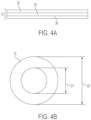
- the plate includes a flexible structural layer 32, an adhesive layer 34, and a peel-away backing layer 36.
- the backing layer 36 covers and protects the adhesive layer 34 until just before the dressing 10 is to be installed. During installation, the backing layer 36 can be removed, thereby exposing the adhesive layer 34 for attachment to the patient's skin.
- Any of a variety of adhesives known in the art can be used for attaching the plate 12 to the patient's skin and the adhesive can be chosen based on a variety of factors, including for example the quality, sterility, and durability of the seal created, the biocompatibility of the adhesive with human skin or with a particular skin type, and/or cost.
- the plate 12 can be attached to the patient in a variety of ways.
- the plate can include hooks, tabs, and/or apertures through which a suture or other tie-down mechanism can be received, or a suture can be threaded directly through the plate material.
- the plate can also be attached using an adhesive tape such that the tape partially overlaps the proximal surface of the plate 12 and partially overlaps the patient's skin.
- a secondary plate seal support device can be employed to augment the plate-skin seal.
- the plate 12 can be made from a variety of materials known in the art such as various semi-rigid/flexible materials, including polyurethanes such as Pellethane (available from The Dow Chemical Company of Midland, MI, USA), thermoplastic elastomers such as Santoprene (available from ExxonMobil Chemical of Houston, TX, USA), polyisoprene elastomers, medium to high durometer silicone elastomers, and/or any combination thereof.
- the plate can also be formed of various polymers, including polycarbonates and polyetheretherketone (PEEK), metals such as titanium or stainless steel, composites such as carbon-fiber reinforced PEEK, various ceramic materials, and/or any combination thereof.
- the plate can also be formed from any other suitable fabrics, foams, plastics, and/or metals known in the art.
- the plate is generally in the form of a thin annular ring having an inner diameter D1 and an outer diameter D2.
- the plate 12 can also be constructed in virtually any other shape, such as rectangular or elliptical.
- the plate 12 is sized in accordance with the catheter to which it will be applied.
- the inner diameter D1 of the plate 12 can be sized such that it is slightly larger than the diameter of the catheter.
- the outside diameter D2 of the plate 12 can be chosen based in part on the strength of the adhesive used to ensure that an adequate surface area of the plate 12 is adhered to the patient to maintain a strong and stable seal.
- the plate can be in the form of an annular ring having an inner diameter of approximately 0.5 mm to approximately 20 mm and an outer diameter of approximately 2 mm to approximately 100 mm.
- the sheath 14 can be formed integrally with the plate 12 or it can be attached thereto using a variety of techniques, so long as a sterile seal exists therebetween.
- the distal end of the sheath 14 can be sandwiched between multiple layers of the plate 12, or it can be attached to the plate 12 using an adhesive.
- a variety of other methods known in the art can also be employed, such as sonic welding, frictional engagement, etc.
- the sheath 14 is generally in the form of an elongate flexible tube. While the illustrated sheath 14 is flexible, the sheath 14 and/or dressing 10 can also be rigid or semi-rigid, which can advantageously permit longitudinal or other movement of the catheter relative to the patient to be further restricted by the dressing.
- the surface of the sheath can be pleated or folded in an accordion-like fashion such that the sheath 14 is extendible from a compressed state to an expanded state (see FIGS. 2A-2B ).
- the sheath can be formed from a stretchable material to facilitate longitudinal extension. Exemplary materials from which the sheath can be formed include a clear flexible plastic, similar to that used for other medical-surgical grade materials and devices.
- sheath can have a combination of optimal attributes such as flexibility, strength, durability, breathability, microbial resistance, etc.
- Other exemplary sheath materials include silicone, polyisoprene, other elastomers or rubbers, and/or any combination thereof. Any other suitable material known in the art can also be used.
- the distal end 38 of the sheath 14 is configured to sealably attach to the plate 12, as describe above.
- the proximal end 40 of the sheath 14 is configured to seal around a catheter and can optionally include a sealing element 16.
- the sealing element 16 is in the form of a flexible gasket ring.
- the sheath 14 can be molded around the sealing element 16, can be bonded thereto using an adhesive, or can be attached thereto using any other suitable method known in the art.
- the sealing element 16 and the sheath 14 can sealably mate to a catheter.
- the sheath 14 is shown advanced proximally along a catheter 24 and over a portion of the nose 42 of a 3-into-1 catheter hub 44.
- the nose 42 of the catheter hub 44 has a generally conical tapered surface.
- the sealing element 16 is stretched over the nose 42 such that the resilient properties of the sealing element 16 cause it to exert a radially inward force against the nose 42. When advanced far enough along the nose 42, this force can create a sealing engagement between the hub 44 and the sheath 14 and/or the sealing element 16.
- a sealing element 16 in the form of a stretchable gasket ring is illustrated, such structure is not necessarily required.
- the sheath 14 itself can have flexible and resilient properties that would facilitate sealing engagement with a catheter.
- a seal between the sheath 14 and a catheter can be effected in a variety of other ways, including for example adhesive bonding, clamping, balloon pressure inflation, and/or magnetic coupling.
- the catheter dressing 10 can also include an absorbent element 48 disposed within the sheath 14.
- the absorbent element 48 can be a strip of sterile gauze material positioned adjacent to the skin surface 28 of the patient.
- the absorbent element 48 can absorb any moisture, condensation, or fluid seepage emanating from the catheter insertion site, from the patient's skin, or otherwise present within the sealed catheter dressing 10.
- An antimicrobial-containing or antibiotic-containing element can also be disposed within the sheath 14 and can optionally be configured to release one or more cleansing/sterilizing agents over time.
- the sheath 14 or dressing 10 itself can be formed from an antibiotic or antimicrobial impregnated material and can release said antibiotic or antimicrobial over time.
- the sheath can also optionally include an access portal 46 for accessing and manipulating the internal volume and contents of the sheath 14.
- the access portal 46 can permit infusion of cleansing, sanitizing, and/or antimicrobial type solutions, to clean or replace the absorbent element 48, or to permit the infusion of sterilizing gas or use of another sterilizing material.
- the access portal 46 can also be used to expose the sealed volume of the dressing and the catheter insertion site to ultraviolet or other sanitizing radiation, or to remove a sample or specimen from the dressing 10 for testing.
- the access portal 46 can also be used to alter various conditions within the sealed dressing 10, such as pH, temperature, humidity, sterility, etc.
- the sheath 14 can be transparent to allow for visualization and monitoring of the internal condition and contents of the sealed volume and the catheter insertion site.
- the entire sheath 14 can be formed of a transparent material as illustrated in FIG. 5A , or the sheath can include one or more transparent windows at various points along an outer surface thereof.
- FIGS. 5B and 5C illustrate a standard catheter hub 50.
- the hub 50 includes a first, proximal end 52 for coupling to a fluid conveying device such as a syringe or IV line.
- the hub further includes a second, distal end 54 that is in fluid communication with the proximal end 52 and that is configured to couple to an implantable catheter 24.
- the standard catheter hub 50 can be circumferentially sealed by advancing the sheath 14 and/or sealing element 16 proximally along a tapered outer surface of the hub 50.
- the catheter dressing 10 can be part of a catheter dressing assembly that can further include an intermediate coupling member.
- the coupling member has a distal end that is in fluid communication with an implantable catheter.
- the proximal end of the coupling member can include a valve such as a Luer-type connector, a MicroCLAVE-type connector, a threaded fitting, and/or a friction fitting.
- the valve can also be a blunt injection site or can be configured to couple to a variety of fluid conveying devices, such as syringes, IV lines, catheter extensions, and the like.
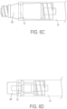
- FIG. 5D illustrates one embodiment of a coupling member in the form of a MicroCLAVE-type connector 56.
- the connector 56 includes fittings 58, 60 at either end configured to couple the connector to various fluid conveying devices known in the art, including for example implantable catheters.
- the main body of the connector 56 includes a tapered outer surface 62 over which the sheath 14 and/or sealing element 16 can be advanced to form a sterile seal.
- FIG. 5E shows another embodiment of a coupling member in the form of a Luer-type connector 64.
- the Luer-type connector includes fittings 66, 68 at either end configured to couple the connector 64 to various fluid conveying devices known in the art, including for example implantable catheters.
- the main body of the connector 64 includes an outer surface over which the sheath 14 and/or sealing element 16 can be advanced to form a sterile seal. While MicroCLAVE-type and Luer-type connectors are specifically illustrated and described herein, a person having ordinary skill in the art will appreciate that any suitable fluid conveying structure can be used as a coupling member.
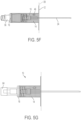
- FIG. 5F illustrates a catheter dressing 10 sealed around an implanted catheter 24 that is coupled to a MicroCLAVE-type connector 56.
- an adhesive plate 12 circumferentially surrounds a catheter insertion site and is adhered to the skin 28 of a patient.
- a sheath 14 extends proximally from the adhesive plate 12 to the connector 56.
- a sealing element 16 at the proximal end of the sheath 14 is drawn distally against the tapered surface of the connector 56, resulting in a sterile seal between the sheath 14 and the connector 56.
- FIG. 5G shows a similar catheter dressing 10 sealed around a Luer-type connector 64. As shown, the sealing element 16 at the proximal end of the sheath 14 frictionally engages the central body of the connector 64, forming a sterile seal therewith.
- the catheter dressing assembly can also include a variety of catheter components that are specifically tailored for receiving the sheath 14 and/or the sealing element 16 of the catheter dressing 10.
- catheter bodies, catheter hubs, MicroCLAVE-type connectors, Luer-type connectors, and/or any intermediate-type connector directly attached in luminal continuity with the catheter can all be modified to include an attachment mechanism to enhance the integrity and stability of the dressing seal. For example, as shown in FIGS.
- a catheter hub 50', a catheter hub 44', a MicroCLAVE-type connector 56', and/or a Luer-type connector 64' can each be modified to include an annular groove 70 formed in an outer surface thereof configured to receive the sealing element 16 and/or a portion of the sheath 14 therein.
- an annular groove 70 formed in an outer surface thereof configured to receive the sealing element 16 and/or a portion of the sheath 14 therein.
- inclusion of such a groove can provide for a more durable and tighter seal between the catheter components 50', 44', 56', 64' and the sheath 14.
- the dressing can be configured to secure the catheter in such a position, and to prevent inadvertent movement of the catheter relative to the patient.
- securement devices can be provided that are configured to further secure the catheter and/or the catheter dressings and dressing assemblies described herein to the patient.
- the securement device can also provide additional strength and stability to the seal between the sheath and the catheter.
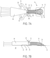
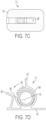
- a securement device in the form of a clamp 72 can be used to anchor the catheter 24 and/or catheter dressing 10 to the patient 26.
- the clamp 72 includes a planar base portion 78 and an upright clamping portion 88.
- the clamping portion 88 includes first and second levers 80, 82 and a ratchet and pawl mechanism 84, 86. Squeezing the first and second levers 80, 82 towards each other causes the inner diameter of the clamping portion 88 to decrease as the pawl 86 rides over one or more ratchet teeth 84.
- the ratchet and pawl mechanism 84, 86 is effective to prevent movement of the first and second levers 80, 82 away from each other and thus to prevent diametrical expansion of the upright clamping portion 88.
- the first lever 80 can be actuated to disengage the pawl 86 from the ratchet teeth 84, thereby permitting the inner diameter of the clamping portion 88 to expand and ultimately open.
- it can be formed from any flexible yet semi-rigid material known in the art.
- an implanted catheter 24 is shown lying substantially flat against the patient 26 and dressed with a catheter dressing 10 as described herein.
- An adhesive pad 74 which can have a construction similar or identical to that of the adhesive plate 12, is used to attach the central line catheter hub 44 and the clamp 72 to the patient.
- the planar base portion 78 of the clamp and the lateral ears 90, 92 of the hub 44 can be affixed to the adhesive pad 74 using a variety of techniques known in the art.
- the clamp 72 can be positioned with respect to the hub 44 such that the upright clamping portion 88 is substantially aligned with the seal region 22 defined by the sheath 14, hub 44, and/or sealing element 16.
- the clamp 72 can further include a inner gasket ring 76 configured to prevent abrasion of the sheath 14 and/or sealing element 16 by the clamp 72.
- the gasket ring 76 can also ensure that the radial force applied by the clamp 72 is substantially uniform about the circumference of the seal region 22.
- catheter dressing 10, clamp 72, and/or catheter 24 are generally described herein as being attached directly to the skin of a patient, other indirect attachment means are also possible.
- any of these structures could instead be attached first to a wrap, pad, bandage, or the like which can then in turn be attached to the patient.
- the clamp 72 can optionally be free floating (e.g., can be provided without the base portion 78) and can be applied to the dressing after it is installed around a catheter, as discussed in greater detail below.
- the plate, sheath, coupling member, and clamp can be provided as a single unitary dressing device 110.
- the inventive device 110 generally includes a folding adhesive plate 112, a coupling member or coupling body 100, and a flexible sheath 114.
- the folding adhesive plate 112 is configured to attach to the skin 28 of a patient 26 and includes an aperture 113 formed therein for receiving an implantable catheter 24 therethrough.
- the coupling body 100 is fixedly attached to the adhesive plate 112 such that the flexible sheath 114 can extend from a ramped surface 102 of the coupling body 100 to a proximal surface of the folding plate 112 to form a sealed volume around the aperture 113.
- a sterile sealed volume is created around the site.
- the coupling body 100 can include an access portal 146 for accessing the sealed volume of the device.
- the coupling body 100 also includes a first fitting 104 disposed within the sealed volume and configured to couple to an implanted catheter 24.
- a second fitting 106 is also provided to facilitate insertion or removal of fluids from the implanted catheter 24.
- the inventive dressing device 110 is effective to create a circumferential seal around a catheter insertion site and an implanted catheter 24 and to prevent movement (e.g., longitudinal, lateral, and/or rotational) of the implanted catheter 24.
- the device can be placed on a skin surface 28 adjacent to a catheter insertion side with the adhesive plate 112 in a folded position.
- the external portion of the implanted catheter 24 can be coupled to the first fitting 104 of the coupling body 100.
- the adhesive plate can then be lowered to an unfolded position in which it lies substantially flat against the patient's skin surface 28 and is adhered thereto, thereby surrounding the catheter insertion site and enclosing it within the aperture 113.
- the dressing device 110 defines a sealed volume around the implanted catheter 24 and the catheter insertion site beneath the sheath 114.
- the sealed volume is accessible via the access port 146 and the catheter is accessible via the second fitting 106 of the coupling body 100.
- FIGS. 9A-9D illustrate one exemplary method for sealing an implantable catheter 24 that is coupled to a catheter hub 50.
- a catheter dressing 10 is configured with the flexible sheath 14 in a compressed state and a catheter 24 is inserted therethrough.
- the dressing 10 is advanced proximally along the catheter 24 and the catheter hub 50 until the sealing element 16 of the sheath 14 forms a satisfactorily tight seal with the hub 50, as shown in FIG. 9B .
- the catheter can then be inserted into a patient 26 at a catheter insertion site.
- the sheath 14 can then be longitudinally extended along the implanted catheter 24 such that the adhesive plate 12 can be attached to the patient's skin surface 28, thereby forming a sterile circumferential seal around the catheter 24, a portion of the catheter hub 50, and the catheter insertion site.
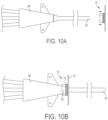
- FIGS. 10A-10D illustrate a similar method wherein a central line catheter hub 44 and an associated catheter insertion site are circumferentially sealed using a catheter dressing 10.
- a catheter dressing 10 is advanced proximally over a catheter 24 and the catheter hub 44 until the sealing element 16 of the dressing 10 is stretched sufficiently over the hub 44 to create a sterile seal.
- the catheter 24 can be partially inserted into a patient 26 and the sheath 14 can be longitudinally extended to a state in which the adhesive plate 12 can be attached and sealed to a skin surface 28 of the patient 26.
- FIGS. 11A-11D illustrate an exemplary method for sealing an implanted catheter 24 using a catheter dressing 10 and an intermediate coupling member.
- an intermediate coupling member - a Luer-type connector 64 - can be passed through the sheath 14 and adhesive plate 12 of a catheter dressing 10 while the sheath 14 is in a compressed state, thereby sealing the sheath 14 and/or the sealing element 16 circumferentially around the body of the Luer-type connector 64, as shown in FIG. 11B .
- the connector 64 can then be coupled to the proximal end of a catheter 24, either before or after the catheter is inserted into a patient, as illustrated in FIG. 11C .
- the sheath 14 can then be longitudinally extended along the connector 64 and catheter 24 to an extended state in which the adhesive plate 12 can be attached to the skin surface 28 of the patient 26, as shown for example in FIG. 11D .
- the adhesive plate 12 can be omitted or formed integrally with the sheath 14 such that the sheath 14 itself is directly attachable to the patient.
- dressings and related methods are provided that include a mechanism for removing and/or replacing the dressing.
- FIG. 12 illustrates one embodiment of a catheter dressing 210 that can be removed from an inserted catheter without requiring the catheter itself to be removed from the patient.
- the dressing 210 includes an adhesive plate 212, a sheath 214, and a sealing element 216, each of which have one or more pre-specified breakpoints 215.
- the break points 215 define a longitudinal, linear seam 231 or path along which the dressing 210 can be separated when sufficient stress is applied.
- the plate 212, the sheath 214, and the sealing element 216 can be separated along the seam 231 defined by the break points 215 to create an opening through which the installed catheter can pass as the dressing 210 is removed.
- the exposed catheter and skin entrance site can be cleaned and/or sterilized as desired.
- a new dressing can then be installed, as described below.
- FIGS. 13A-15C and 17A-18E illustrate various exemplary embodiments of catheter dressings that can be installed around a catheter that is already inserted into a patient. These dressings generally have an open configuration in which they can be placed around an inserted catheter or can be removed from an inserted catheter. During installation, the opened dressing is placed around the catheter and reconstituted into a generally tubular shape using one or more of a variety of attachment mechanisms, including without limitation a friction fit, a male-female snap fit, an adhesive coupling, and/or a latch-type closure, thereby establishing a circumferential seal around the catheter.
- attachment mechanisms including without limitation a friction fit, a male-female snap fit, an adhesive coupling, and/or a latch-type closure, thereby establishing a circumferential seal around the catheter.
- a dressing 310 is shown having a plate 312, a sheath 314, and a sealing element 316.
- the dressing 310 is shown in an opened or unfolded configuration in which the free edges 317, 319 of the sheath 314 are separated such that the sheath 314 does not form a complete tube.
- a first edge 317 of the sheath 314 is provided with a longitudinal female groove 321.
- a second edge 319 of the sheath 314 is provided with a longitudinal male tab 323. Together, the female groove 321 and the male tab 323 form a friction-fit seal along the length of the sheath 314.
- FIG. 13B illustrates a cross-section of the sheath 314. As shown, the female groove 321 and the male tab 323 can be separated such that the sheath 314 can be installed around a catheter that has already been placed. It will thus be appreciated that the male components 319, 327 of the dressing 310 and the female components 317, 325 of the dressing 310 can be mated (as shown in FIG. 13C ) to form a circumferential sterile seal around a catheter that has already been placed, or can be separated to facilitate removal of the dressing 310 from such catheters.
- FIGS. 14A-14C illustrate another exemplary embodiment of a catheter dressing 410 that can be installed around an already-placed catheter.
- the dressing 410 includes a plate 412, a sheath 414, and a sealing element 416.
- the dressing 410 is shown in an opened or unfolded configuration in which opposed free edges 417, 419 of the dressing 410 are separated such that the dressing 410 does not form a complete tube.
- a first edge 417 of the dressing 410 is provided with an adhesive flap 429. When installed around a catheter, the first edge 417 can be placed adjacent the second edge 419 and the adhesive flap 429 can be folded across the gap between the edges 417, 419 to form a circumferential sterile seal around the catheter.
- FIG. 14B illustrates a cross-section of the sheath 414.
- the first edge 417 and the second edge 419 can be separated such that the sheath 414 can be installed around a catheter that has already been placed.
- the edges 417, 419 can be mated as shown in FIG. 14C by folding over and adhering the adhesive flap 429 to form a circumferential sterile seal around a catheter that has already been placed.
- the flap 429 can be peeled back and the edges 417, 419 separated to form an opening through which the catheter can pass as the dressing 410 is removed.
- FIGS. 15A-15C illustrate another exemplary embodiment of a catheter dressing 510 that can be installed around an already-placed catheter.
- the dressing 510 includes a plate 512, a sheath 514, and a sealing element 516 and generally combines the friction-fit features of the catheter dressing 310 of FIGS. 13A-13C and the adhesive flap features of the catheter dressing 410 of FIGS. 14A-14C .
- the dressing 510 is shown in an opened or unfolded configuration in which opposed free edges 517, 519 of the dressing 510 are separated such that the dressing 510 does not form a complete tube.
- a first edge 517 of the sheath 514 is provided with an adhesive flap 529 and a longitudinal female groove 521.
- a second edge 519 of the sheath 514 is provided with a longitudinal male tab 523.
- the male tab 523 can form a friction-fit seal with the female groove 521.
- the adhesive flap 529 can be folded over the second edge 519 of the sheath and adhered to an exterior thereof to reinforce the sealing engagement.
- the plate 512 and the sealing element 516 are similarly provided with female receptacles 525 and male projections 527 which can be selectively mated to form a friction-fit seal at the breakpoints of the plate 512 and the sealing element 516.
- the adhesive flap 529 can extend the full length of the dressing 510 (e.g., across the plate 512 and the sealing member 516 as well).
- the first edge 517 and the second edge 519 can be separated such that the sheath 514 can be installed around a catheter that has already been placed.
- the adhesive flap 529 is shown as being formed on the same edge 517 of the sheath 514 as the female groove 521, it can also be formed on the opposite edge 519 of the sheath 514 (e.g., adjacent the male tab 523).
- the edges 517, 519 can be mated as shown in FIG. 15C by engaging the male tab 523 and the female groove 521 and folding over and adhering the adhesive flap 529 to form a circumferential sterile seal around a catheter that has already been placed.
- the flap 529 can be peeled back and the edges 517, 519 separated to form an opening through which the catheter can pass as the dressing 510 is removed.
- FIGS. 16A-16E illustrate another embodiment of a catheter dressing 610 that generally includes a flexible sheath 614 that is formed at a non-ninety-degree angle relative to an adhesive plate 612.
- the angle between the sheath 614 and the plate 612 can advantageously make the dressing 610 easier to install and can reduce forces that tend to separate the plate 612 from the patient's skin 628.
- An access portal 646 can be provided in a sidewall of the sheath 614 as described above for accessing and manipulating the internal volume and contents of the sheath 614.
- a sealing element 616 formed at a proximal end of the sheath 614 can be sealably mated to a catheter 624 and/or a specially-designed catheter hub 644.
- the sealing element 616 is advanced proximally over the nose 642 of the catheter hub 644 until it engages an annular groove 670 formed thereon.
- the dressing 610 when installed as shown, provides a sterile circumferential seal around the catheter 624, the catheter hub 644, and the catheter-skin insertion site.
- a variety of techniques can be used to effect a sealing engagement between the sheath 614 and the catheter 624 or catheter hub 644.
- a sealing element 616 in the form of a stretchable gasket ring can be employed to form a sealing engagement with a corresponding groove 670 formed on an outer surface of the catheter hub 644.
- the resilient properties of the sealing element 616 can cause it to exert a radially inward force against the groove 670, thereby forming a sterile seal.
- a securement device such as a clamp 672 shown in FIG. 16E can be used to hold the sealing element 616 in position around the catheter hub 644 or to reinforce the seal formed therebetween.
- the clamp 672 operates substantially in the same manner as the clamping portion 88 shown in FIGS. 7A-7D .
- An adhesive pad 674 can be provided to attach the catheter hub 644 to the patient's skin 628, and the clamp 672 can optionally include a base portion (not shown) which can be coupled to the adhesive pad 674 as described above.
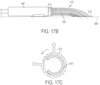
- FIGS. 17A-17C illustrate another embodiment of a catheter dressing 610' that is substantially identical to the catheter dressing 610 shown in FIGS. 16A-16C except that it includes features for removing the dressing from, and installing the dressing around, an already-placed catheter.
- the dressing 610' includes a sheath 614' coupled to an adhesive plate 612' at a non-ninety-degree angle.
- the dressing 610' is provided with a longitudinal seam 631' that extends the entire length of the sheath 610', the adhesive plate 612', and a sealing member 616' (shown in FIG. 17C ).
- the dressing 610' can be selectively separated and attached at the seam 631' to facilitate installation of the dressing 610' around a catheter that has already been inserted into a patient or to facilitate removal of the dressing 610' from such catheters.
- the seam 631' can be formed with a friction-fit arrangement (e.g., as shown in FIGS. 13A-13C ), with an adhesive flap arrangement (e.g., as shown in FIGS. 14A-14C ), or with a combination thereof (e.g., as shown in FIGS. 15A-15C ).
- the seam 631' can be formed on a side of the sheath 614' that intersects the plate 612' at an obtuse angle. This can advantageously permit joining of the free edges of the sheath 614', the free edges of the adhesive plate 612', and the free edges of the sealing member 616' to occur almost in a single plane, which can ease installation and removal of the dressing 610'.
- a plate seal support device 633' can optionally be provided to reinforce and support the seal formed between the adhesive plate 612' and a patient's skin, as discussed in further detail below.
- the dressing 610' can be placed around an inserted catheter 624' and catheter hub 644'.
- the dressing 610' can then be joined along the seam 631' and the adhesive plate 612' can be affixed to the patient's skin 628'.
- a C-shaped gasket sealing element 616' and an associated clamp 672' as shown in FIG. 17C can then be installed around the hub 644' and the dressing 610' to complete a sterile circumferential seal around the catheter 624', the hub 644', and the catheter-skin insertion site.
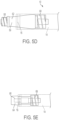
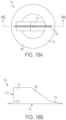
- FIGS. 18A-18E illustrate another embodiment of a catheter dressing 710 that permits a rigid or semi-rigid snap-fit seal to be formed with a catheter or a catheter hub.
- the dressing 710 includes a unitary body 700 having an adhesive base portion 712 configured to be adhered to a patient's skin circumferentially around a catheter-skin insertion site.
- the base portion 712 is generally ring-shaped and defines a distal opening 715 sized to surround the insertion site.
- the base portion 712 can also include a re-sealable seam 731 to facilitate installation of the dressing 710 around a catheter that is already inserted into a patient.
- a rigid or semi-rigid proximal portion 714 extends vertically upward from a surface of the base portion 712 opposite to the surface that is adhered to the patient.
- the proximal portion 714 defines a proximal opening 713.
- An inner lumen 717 extends between the proximal opening 713 of the proximal portion 714 and the distal opening 715 of the base portion 712, defining a chamber in which a catheter can be positioned.
- the re-sealable seam 731 can also extend along the proximal portion 714 to allow the entire body 700 to be selectively separated and reattached in a sealable fashion (e.g., when it is necessary to remove or install the dressing 710 from an already-inserted catheter).
- the seam 731 can be formed by any of the aforementioned mechanisms, including a friction-fit, an adhesive flap, a latch-type engagement, or any combination thereof.
- the opposed free edges of the sheath 714 are provided with corresponding male tabs 725 and female receptacles (not shown) to facilitate a friction-fit seal therebetween.
- the proximal portion 714 can also include one or more access portals 746 for accessing and manipulating the interior and contents of the dressing 710.
- the dressing 710 can include an annular groove 771 formed in an interior surface thereof, adjacent to the proximal opening 713, that is configured to receive a corresponding annular projection 773 formed on a catheter line 724 (as shown in FIG. 18D ) or on a catheter hub 744 (as shown in FIG. 18E ).
- the annular groove 771 and the proximal opening 713 can also be seen as forming an annular lip which can engage a corresponding slot or groove 770 formed in the catheter hub 744.
- This groove-projection interface provides a snap-fit sealing engagement between the dressing 710 and the catheter 724 or the hub 744, which can advantageously secure the catheter 724 in position and prevent movement (e.g., longitudinal, lateral, and/or rotational) of the catheter 724 relative to the patient.
- FIGS. 19A-19C illustrate one exemplary embodiment of a catheter seal support device 800 for forming or reinforcing a seal at the dressing-catheter junction.
- the support device 800 is configured to circumferentially surround a catheter having a dressing disposed therearound.
- the support device 800 can be effective to squeeze and clamp the dressing around the catheter, holding it firmly in place and reinforcing or forming a sterile seal.
- the support device 800 generally includes a clamping portion 888 and an inner gasket ring 876.
- the clamping portion 888 includes first and second levers 880, 882 and a ratchet and pawl mechanism 884, 886. Squeezing the first and second levers 880, 882 towards each other causes the inner diameter of the clamping portion 888 to decrease as the pawl 886 rides over one or more ratchet teeth 884. As the first and second levers 880, 882 are advanced toward one another, the ratchet and pawl mechanism 884, 886 is effective to prevent movement of the first and second levers 880, 882 away from each other and thus to prevent diametrical expansion of the clamping portion 888.
- the first lever 880 can be actuated to disengage the pawl 886 from the ratchet teeth 884, thereby permitting the inner diameter of the clamping portion 888 to expand and ultimately open.
- the support device 800 can be formed from any flexible yet semi-rigid material known in the art.
- the gasket ring 876 can be positioned about an inner circumference of the clamping portion 888 and can be configured to prevent abrasion of a dressing around which the clamping portion 888 is placed.
- the gasket ring 876 can also ensure that the radial force applied by the support device 800 is substantially uniform about the circumference of the dressing.
- the gasket ring 876 can have an opening 877 such that the gasket ring 876 is substantially C-shaped and thus can be installed around an already-dressed or already-inserted catheter.
- the opening 877 in the gasket ring 876 be placed on the opposite side of the dressing (e.g., such that the opening 877 is disposed 180 degrees from the seam in the dressing). This can desirably provide a more stable, reliable seal.
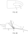
- FIGS. 20A-20D show one embodiment of a plate seal support device 900.
- the support device 900 generally comprises a circular adhesive ring 901.
- the ring 901 has a break 903 formed therein such that the ring 901 can be opened, placed around an already-installed dressing, and then closed (e.g., reconstituted as a circle).
- the ring 901 can include an overlap region 905 such that the free ends of the ring overlap one another. In one embodiment, the overlap region 905 can extend between 30 and 60 degrees around the ring 901.
- the support device 900 can be placed to further seal the outer edge of a catheter dressing's adhesive plate to a patient's skin and to prevent the plate of the dressing from inadvertently separating at a re-sealable seam.
- FIG. 20C illustrates an exemplary catheter dressing 910 with which the support device 900 can be used.
- the dressing 910 is adhered to a patient's skin 928 via a circular adhesive plate 912.
- a longitudinal seam 931 is formed in the dressing 910 (including in the plate 912) to allow the dressing to be installed on or removed from an already-placed catheter. As shown in FIG.
- the support device 900 can be opened at the break 903, positioned around the dressing 910, and closed such that the overlap portion 905 adheres to a top surface of an opposed free end of the adhesive ring 901.
- the inner diameter of the support device 900 is smaller than the outer diameter of the adhesive plate 912 and the outer diameter of the support device 900 is larger than the outer diameter of the adhesive plate 912. Accordingly, the support device 900 overlaps a portion of the adhesive ring 912 and a portion of the patient's skin 928, thereby reinforcing and/or forming a circumferential seal between the dressing 910 and the skin 928.
- the break 903 and overlap portion 905 of the support device 900 can be positioned on a side of the dressing 910 opposite to the seam 931 such that the two do not overlap.
- the break 903 in the support device 900 can be positioned 180 degrees from the seam 931 in the dressing 910, which can provide a more stable and reliable seal.
- kits can also include catheters of various sizes and types, including customized or modified catheters designed specifically to interface with the dressings and dressing assemblies described herein.
- the devices disclosed herein can be designed to be disposed of after a single use, or they can be designed to be used multiple times. In either case, however, the device can be reconditioned for reuse after at least one use. Reconditioning can include any combination of the steps of disassembly of the device, followed by cleaning or replacement of particular pieces, and subsequent reassembly. In particular, the device can be disassembled, and any number of the particular pieces or parts of the device can be selectively replaced or removed in any combination. Upon cleaning and/or replacement of particular parts, the device can be reassembled for subsequent use either at a reconditioning facility, or by a caregiver immediately prior to a catheterization procedure.
- reconditioning of a device can utilize a variety of techniques for disassembly, cleaning/replacement, and reassembly. Use of such techniques, and the resulting reconditioned device, are all within the scope of the present application.
- the device described herein will be processed before use.
- a new or used device is obtained and if necessary cleaned.
- the device can then be sterilized.
- the instrument is placed in a closed and sealed container, such as a plastic or TYVEK bag.
- the container and device are then placed in a field of radiation that can penetrate the container, such as gamma radiation, x-rays, or high-energy electrons.
- the radiation kills bacteria on the device and in the container.
- the sterilized device can then be stored in the sterile container.
- the sealed container keeps the device sterile until it is opened in the medical field.
- the device is sterilized. This can be done by any number of ways known to those skilled in the art including beta or gamma radiation, ethylene oxide, steam, and/or a liquid bath (e.g., cold soak).
Landscapes
- Health & Medical Sciences (AREA)
- Life Sciences & Earth Sciences (AREA)
- Heart & Thoracic Surgery (AREA)
- Biomedical Technology (AREA)
- Engineering & Computer Science (AREA)
- Anesthesiology (AREA)
- Pulmonology (AREA)
- Hematology (AREA)
- Animal Behavior & Ethology (AREA)
- General Health & Medical Sciences (AREA)
- Public Health (AREA)
- Veterinary Medicine (AREA)
- Biophysics (AREA)
- Media Introduction/Drainage Providing Device (AREA)
Claims (7)
- Dispositif (110) comprenant :une plaque adhésive pliante (112) configurée pour être attachée à la peau d'un patient au niveau d'un site d'insertion de cathéter et présentant une ouverture (113) à travers laquelle un cathéter implanté (24) peut passer ;un manchon flexible (114) s'étendant de façon proximale à partir de la plaque adhésive (112) et configuré pour entourer un segment extérieur du cathéter ;un corps de couplage (100) attaché fixement à la plaque adhésive (112) pour un couplage au segment de cathéter extérieur,la plaque adhésive pliante (112), le manchon (114) et le corps de couplage (100) étant configurés pour former une chambre scellée autour du segment de cathéter extérieur,dans lequel la plaque adhésive pliante (112) est configurée pour fournir un joint circonférentiel autour du site d'insertion, etcaractérisé en ce que le corps de couplage (100) comprend en outre un premier raccord (104) configuré pour se coupler au segment extérieur du cathéter implanté (24) lorsque l'ensemble de garniture de cathéter est scellé autour de celui-ci et un second raccord (106) en communication fluidique avec le cathéter implanté et configuré pour une insertion et un retrait de fluide à partir du cathéter implanté.
- Dispositif selon la revendication 1, dans lequel le corps de couplage (100) comprend un portail d'accès refermable (146).
- Dispositif selon la revendication 1, dans lequel le manchon flexible (114) s'étend à partir d'une surface inclinée (102) du corps de couplage (100) jusqu'à une surface proximale de la plaque pliante (112).
- Dispositif selon la revendication 1, dans lequel la plaque adhésive (112), le manchon (114) et le corps de couplage (100) sont formés intégralement en tant que dispositif unitaire.
- Dispositif selon l'une quelconque des revendications précédentes, dans lequel le manchon (114) comprend en outre au moins un matériau imprégné d'antibiotique ou un matériau imprégné d'antimicrobien.
- Dispositif selon l'une quelconque des revendications précédentes, dans lequel le corps de couplage (100) est configuré pour restreindre un mouvement du segment de cathéter extérieur par rapport au patient.
- Kit comprenant :
le dispositif (110) selon l'une quelconque des revendications précédentes et un cathéter (24).
Applications Claiming Priority (2)
| Application Number | Priority Date | Filing Date | Title |
|---|---|---|---|
| US25592709P | 2009-10-29 | 2009-10-29 | |
| PCT/US2010/054427 WO2011059728A2 (fr) | 2009-10-29 | 2010-10-28 | Garniture de cathéter stérile scellée |
Publications (3)
| Publication Number | Publication Date |
|---|---|
| EP2493544A2 EP2493544A2 (fr) | 2012-09-05 |
| EP2493544A4 EP2493544A4 (fr) | 2013-05-22 |
| EP2493544B1 true EP2493544B1 (fr) | 2024-07-31 |
Family
ID=43926164
Family Applications (1)
| Application Number | Title | Priority Date | Filing Date |
|---|---|---|---|
| EP10830440.3A Active EP2493544B1 (fr) | 2009-10-29 | 2010-10-28 | Garniture de cathéter stérile scellée |
Country Status (10)
| Country | Link |
|---|---|
| US (2) | US9808601B2 (fr) |
| EP (1) | EP2493544B1 (fr) |
| JP (1) | JP2013509256A (fr) |
| KR (1) | KR20120087964A (fr) |
| CN (1) | CN102905751B (fr) |
| AU (1) | AU2010319924B2 (fr) |
| BR (1) | BR112012010227A2 (fr) |
| CA (1) | CA2779137C (fr) |
| ES (1) | ES2984625T3 (fr) |
| WO (1) | WO2011059728A2 (fr) |
Families Citing this family (44)
| Publication number | Priority date | Publication date | Assignee | Title |
|---|---|---|---|---|
| US8597253B2 (en) | 2007-04-20 | 2013-12-03 | Bard Access Systems | Huber needle with safety sheath |
| US9180275B2 (en) | 2011-01-31 | 2015-11-10 | Robert E. Helm | Catheter-dressing systems with integrated flushing mechanisms |
| US10682507B2 (en) | 2009-10-29 | 2020-06-16 | One Iv Solutions, Llc | Catheter extension with integrated circumferentially sealing securement dressing |
| US9808601B2 (en) * | 2009-10-29 | 2017-11-07 | Robert E. HELM, JR. | Sealed sterile catheter dressings |
| US20140066894A1 (en) | 2010-09-10 | 2014-03-06 | C. R. Bard, Inc. | Self-Sealing Pad for a Needle-Based Infusion Set |
| US10525234B2 (en) | 2010-09-10 | 2020-01-07 | C. R. Bard, Inc. | Antimicrobial/haemostatic interface pad for placement between percutaneously placed medical device and patient skin |
| US9248234B2 (en) | 2010-09-10 | 2016-02-02 | C. R. Bard, Inc. | Systems for isolation of a needle-based infusion set |
| WO2012106088A2 (fr) * | 2011-01-31 | 2012-08-09 | Helm Robert E Jr | Système cathéter-pansement intravasculaire stérile, à jonction étanche instantanée |
| US9155866B2 (en) * | 2012-09-13 | 2015-10-13 | Becton, Dickinson And Company | Luer securement device |
| WO2013152209A1 (fr) * | 2012-04-04 | 2013-10-10 | The Children's Mercy Hospital | Aiguille pour orifice et ses procédés d'utilisation |
| WO2013165578A1 (fr) | 2012-04-30 | 2013-11-07 | Ivwatch, Llc | Appareil pour un capteur de spectre électromagnétique surveillant une perfusion intravasculaire |
| GB201222782D0 (en) * | 2012-12-18 | 2013-01-30 | Bansal Kanika | Device |
| EP2745869A1 (fr) | 2012-12-21 | 2014-06-25 | ECP Entwicklungsgesellschaft mbH | Agencement d'écluse pour l'introduction d'un corps en forme de tige, en particulier d'un cathéter, dans le corps d'un patient |
| AU2014306542B2 (en) | 2013-08-16 | 2019-02-14 | Np Medical Inc. | Catheter connection and stabilization device and methods of using same |
| WO2016141291A1 (fr) * | 2015-03-04 | 2016-09-09 | Viaderm, Llc | Appareil de pénétration de la peau assisté par vide à interface externe |
| US10478546B2 (en) * | 2015-09-15 | 2019-11-19 | Surmodics, Inc. | Hemodialysis catheter sleeve |
| US10632284B2 (en) | 2015-10-02 | 2020-04-28 | Rabie Stephan | Catheter port |
| US10918835B2 (en) | 2016-03-31 | 2021-02-16 | Surmodics, Inc. | Delivery system for active agent coated balloon |
| JP7132633B2 (ja) | 2016-12-27 | 2022-09-07 | ヴァソニクス・インコーポレイテッド | カテーテルハウジング |
| JP6507191B2 (ja) * | 2017-03-13 | 2019-04-24 | 有限会社昭和精機 | カテーテル出口部の洗浄ケア装置 |
| CN107485737A (zh) * | 2017-08-14 | 2017-12-19 | 广州润虹医药科技股份有限公司 | 一种医用创面护理装置 |
| KR101985191B1 (ko) * | 2017-08-29 | 2019-06-03 | 가톨릭관동대학교산학협력단 | 요로 감염 방지를 위한 멸균 카테터 모듈 및 그 조립 방법 |
| DE102017009674A1 (de) * | 2017-10-17 | 2019-04-18 | Drägerwerk AG & Co. KGaA | Abdichtungsvorrichtung und Medizingerät mit zumindest einer Abdichtungsvorrichtung |
| EP3720532B1 (fr) * | 2017-12-07 | 2023-08-30 | Pavini, Marie | Dispositif de protection de tube endotrachéal avec système de maintien facultatif et capteur facultatif |
| CN108310592B (zh) * | 2018-01-30 | 2020-08-14 | 温州市人民医院 | 一种透析导管固定装置 |
| US10827909B2 (en) * | 2018-02-14 | 2020-11-10 | Marla F. Bashour | Alimentary engagement device |
| EP3765139A4 (fr) | 2018-03-12 | 2021-12-01 | NP Medical Inc. | Système de gestion de site d'accès vasculaire |
| WO2019236956A2 (fr) | 2018-06-08 | 2019-12-12 | Smiths Medical Asd, Inc. | Dispositif et procédé de séquestration du sang |
| US20200330732A1 (en) * | 2019-04-18 | 2020-10-22 | Robert E. Helm | Catheter dressings, systems and methods of use |
| CN114206410B (zh) * | 2019-07-31 | 2024-12-10 | 何塞·拉米雷斯 | 用于血液透析输药的接入组件 |
| CN110840654A (zh) * | 2019-10-24 | 2020-02-28 | 江苏省人民医院(南京医科大学第一附属医院) | 一种专用于治疗身体褶皱部位皮肤破损的敷料 |
| US11291801B2 (en) | 2020-01-31 | 2022-04-05 | Np Medical Inc. | Patient access site securement system |
| US12246145B2 (en) * | 2020-06-29 | 2025-03-11 | Becton, Dickinson And Company | Dressing-based traction device and related systems and methods |
| US11464945B1 (en) * | 2020-07-07 | 2022-10-11 | Willie Henderson | Catheter canal |
| KR102474273B1 (ko) * | 2020-08-20 | 2022-12-06 | 인제대학교 산학협력단 | 인체용 튜브 홀더 |
| US20220062590A1 (en) * | 2020-09-02 | 2022-03-03 | MedXScience LLC | Medical dressing |
| WO2022081650A1 (fr) * | 2020-10-14 | 2022-04-21 | Opcare Llc | Appareil et procédés d'ancrage de cathéter améliorés |
| CN112121285A (zh) * | 2020-10-27 | 2020-12-25 | 扬州大学 | 一种用于固定引流管的锁紧装置 |
| WO2023150792A1 (fr) * | 2022-02-07 | 2023-08-10 | One Iv Solutions, Llc | Étanchéification et fixation d'un système de pansement pour dispositifs d'accès vasculaire |
| WO2023239993A1 (fr) * | 2022-06-09 | 2023-12-14 | Novaflux Inc. | Dispositif d'extension-rallongement de cathéter de libération de médicament et tube d'extension de cathéter |
| JP2024033758A (ja) * | 2022-08-31 | 2024-03-13 | テルモ株式会社 | ドレッシングフィルムおよび除菌方法 |
| JP2025530460A (ja) * | 2022-09-21 | 2025-09-11 | クズモ,インコーポレイテッド | カテーテルスタビライザ及びグリップ |
| KR20240045778A (ko) * | 2022-09-30 | 2024-04-08 | 충남대학교병원 | 정맥관 및 음압강 내의 카테터 제거 시의 공기 흡인 방지가 가능한 장치 |
| US20240252790A1 (en) * | 2023-01-30 | 2024-08-01 | Becton, Dickinson And Company | Catheter system having a swab for site disinfection |
Family Cites Families (93)
| Publication number | Priority date | Publication date | Assignee | Title |
|---|---|---|---|---|
| US3683911A (en) * | 1970-08-13 | 1972-08-15 | Pelam Inc | Protective seal for catheter |
| US3900026A (en) * | 1973-11-19 | 1975-08-19 | William H Wagner | Device for holding and protecting intravenous injection needles |
| US3918446A (en) * | 1974-05-03 | 1975-11-11 | E Med Corp | Securement device for intravenous catheter and its tubing |
| US4327723A (en) | 1980-05-13 | 1982-05-04 | Arrow International, Inc. | Catheter shield |
| US4515592A (en) | 1980-05-13 | 1985-05-07 | Arrow International, Inc. | Catheter shield |
| US4392853A (en) * | 1981-03-16 | 1983-07-12 | Rudolph Muto | Sterile assembly for protecting and fastening an indwelling device |
| DE3140192C2 (de) * | 1981-10-09 | 1985-05-02 | Dr. Eduard Fresenius, Chemisch-pharmazeutische Industrie KG, 6380 Bad Homburg | Katheter |
| US4464178A (en) | 1981-11-25 | 1984-08-07 | Dalton Michael J | Method and apparatus for administration of fluids |
| US4634433A (en) * | 1982-10-07 | 1987-01-06 | Cook, Incorporated | Flexible sheath assembly for an indwelling catheter |
| US4551137A (en) | 1982-10-07 | 1985-11-05 | Cook Incorporated | Flexible sheath assembly for an indwelling catheter |
| US4551136A (en) | 1983-04-11 | 1985-11-05 | Medex, Inc. | Pressure infusor |
| US4563177A (en) | 1983-12-22 | 1986-01-07 | Kamen Dean L | Catheter stabilization pad |
| US4781695A (en) * | 1986-07-11 | 1988-11-01 | Dalton Michael J | Implantable fluid dispenser |
| US4767411A (en) | 1987-07-14 | 1988-08-30 | Edmunds L Henry | Protective catheter sleeve |
| US4840613A (en) * | 1988-04-27 | 1989-06-20 | Menlo Care, Inc. | Protective sheath for catheter assembly |
| US4966590A (en) | 1988-12-13 | 1990-10-30 | Kalt Medical Corporation | IV Clamp with membrane dressing |
| US5074847A (en) * | 1989-05-01 | 1991-12-24 | Century Plastics, Inc. | Needle shield with transparency maintaining coating |
| US5232453A (en) | 1989-07-14 | 1993-08-03 | E. R. Squibb & Sons, Inc. | Catheter holder |
| US5702371A (en) | 1989-07-24 | 1997-12-30 | Venetec International, Inc. | Tube fitting anchoring system |
| US5112313A (en) * | 1989-08-11 | 1992-05-12 | Sallee Patricia L | IV cover/protector |
| US5350360A (en) * | 1990-03-01 | 1994-09-27 | Michigan Transtech Corporation | Implantable access devices |
| SE470052B (sv) | 1991-01-25 | 1993-11-01 | Lic Hygien Ab | Venkateterförband |
| US5215532A (en) | 1991-03-26 | 1993-06-01 | Atkinson Meredith C | Catheter device with easily deployed retainer |
| US5116324A (en) | 1991-07-15 | 1992-05-26 | Brierley Carol L | Protector for IV site |
| US5238010A (en) | 1991-10-11 | 1993-08-24 | Abbott Laboratories | Catheter site shield |
| US5695466A (en) | 1993-07-23 | 1997-12-09 | Icu Medical, Inc. | Medical connection indicator and method of use |
| US5694686A (en) | 1991-12-18 | 1997-12-09 | Icu Medical, Inc. | Method for assembling a medical valve |
| US5336195A (en) | 1992-03-19 | 1994-08-09 | Yousef Daneshvar | Special wraps, dilators and foley catheters |
| ES2141167T3 (es) | 1992-09-10 | 2000-03-16 | Mcneil Ppc Inc | Vendaje adhesivo de cateter intravenoso. |
| US5478326A (en) | 1992-12-10 | 1995-12-26 | Shiu; Man F. | Arterial device for control of bleeding from a puncture in an artery wall |
| US5354288A (en) | 1993-02-24 | 1994-10-11 | Minnesota Mining And Manufacturing Company | Low velocity aortic cannula |
| US6827705B2 (en) | 1993-03-19 | 2004-12-07 | Venetec International, Inc. | Catheter anchoring system |
| US5344415A (en) | 1993-06-15 | 1994-09-06 | Deroyal Industries, Inc. | Sterile system for dressing vascular access site |
| USD359120S (en) | 1993-09-24 | 1995-06-06 | I.V. Pro Tek, Inc. | Combined I.V. needle cover and protector |
| US5372589A (en) | 1993-11-24 | 1994-12-13 | Davis; W. Gordon | Fenestrated transparent catheter securing device and method |
| US5415642A (en) | 1994-02-03 | 1995-05-16 | Shepherd; Brad | Catheter cover |
| US5577516A (en) | 1994-03-24 | 1996-11-26 | Stat Emergency Medical Products, Inc. | Intravenous catheter support |
| US5776106A (en) * | 1995-01-03 | 1998-07-07 | Matyas; Melanie E. | Replaceable flexible protective cover for an infusion device |
| EP0827416A4 (fr) | 1995-03-28 | 1999-06-09 | Ballard Med Prod | Gaine de catheter anti-contamination a barrieres de filtration/fermeture |
| US5820607A (en) * | 1995-06-05 | 1998-10-13 | Board Of Regents, University Of Texas Systems | Multipurpose anti-microbial silastic sheath system for the prevention of device-related infections |
| US5707348A (en) | 1995-06-06 | 1998-01-13 | Krogh; Steve S. | Intravenous bandage |
| US5662616A (en) * | 1995-07-07 | 1997-09-02 | Bousquet; Gerald G. | Transcutaneous access device |
| US5722959A (en) * | 1995-10-24 | 1998-03-03 | Venetec International, Inc. | Catheter securement device |
| US5686096A (en) | 1995-12-22 | 1997-11-11 | Becton Dickinson And Company | Medical device for the protection of a catheter penetration site |
| US5772636A (en) | 1996-12-02 | 1998-06-30 | Becton Dickinson And Company | Catheter assembly with interlocking telescoping needle shield |
| US5807341A (en) * | 1996-12-11 | 1998-09-15 | Team Medical Llc | Medical catheter dressing device |
| US6213979B1 (en) | 1997-05-29 | 2001-04-10 | Venetec International, Inc. | Medical line anchoring system |
| GB9717821D0 (en) | 1997-08-21 | 1997-10-29 | Spinoza Marc H | Fasteners |
| US6224571B1 (en) | 1997-11-14 | 2001-05-01 | Venetec International, Inc. | Medical line securement device |
| US6132399A (en) | 1998-04-30 | 2000-10-17 | Kimberly-Clark Worldwide, Inc. | Catheter securement dressing and delivery method |
| US5989220A (en) | 1998-05-26 | 1999-11-23 | Retractable Technologies Inc. | Self-retracting IV catheter introducer |
| US6491664B2 (en) | 1998-08-18 | 2002-12-10 | Venetec International, Inc. | Anchoring system for a medical article |
| US6080138A (en) | 1998-09-23 | 2000-06-27 | Lemke; Christy L. | IV protector |
| CA2284210A1 (fr) | 1998-09-28 | 2000-03-28 | Benjamin C. Brown | Trousse jetable pour la fixation d'un catheter d'iv |
| US6099509A (en) | 1999-04-20 | 2000-08-08 | Brown, Jr.; William S. | Disposable kit for securing an I.V. catheter |
| US6375639B1 (en) | 1998-10-09 | 2002-04-23 | Renee F. Duplessie | Intravenous stabilizing device |
| US6738661B1 (en) * | 1999-10-22 | 2004-05-18 | Biosynergetics, Inc. | Apparatus and methods for the controllable modification of compound concentration in a tube |
| EP1296738A1 (fr) | 2000-06-30 | 2003-04-02 | I.V. House, Inc. | Dispositif de securite pour site de perfusion |
| US20050113798A1 (en) | 2000-07-21 | 2005-05-26 | Slater Charles R. | Methods and apparatus for treating the interior of a blood vessel |
| US6413240B1 (en) | 2000-08-03 | 2002-07-02 | Venetec International, Inc. | Dialysis catheter anchoring system |
| US6569121B1 (en) | 2000-10-12 | 2003-05-27 | Benjamin Warren Purow | Sheath device with dressing for prevention of pneumothorax |
| US6517520B2 (en) * | 2000-12-21 | 2003-02-11 | Ethicon Endo Surgery, Inc. | Peripherally inserted catheter with flushable guide-tube |
| US8100857B2 (en) | 2001-07-25 | 2012-01-24 | B. Braun Melsungen Ag | Method and apparatus for indicating or covering a percutaneous puncture site |
| US7294118B2 (en) | 2001-10-24 | 2007-11-13 | Becton, Dickinson And Company | Retractable needle assembly |
| US6571395B1 (en) | 2002-01-11 | 2003-06-03 | A. B. Korkor Medical, Inc. | Protective guard for catheter exit site |
| US6809230B2 (en) | 2002-06-04 | 2004-10-26 | Betty Hancock | Waterproof venipuncture site cover |
| WO2004016309A2 (fr) | 2002-08-15 | 2004-02-26 | Venetec International, Inc. | Dispositif de fixation de catheter |
| US7083598B2 (en) | 2002-08-27 | 2006-08-01 | Jan Liska | Transcutan catheter assembly |
| EP1549367B1 (fr) | 2002-10-11 | 2016-04-06 | Becton Dickinson and Company | Seringue de rincage pourvue d'un piston compressible |
| DK1549376T3 (da) | 2002-10-11 | 2011-12-05 | Becton Dickinson Co | Rensesprøjte med en indretning til at hæmme tilbagestrømning |
| US6827707B2 (en) * | 2003-02-06 | 2004-12-07 | Medical Device Group, Inc. | Venipuncture site protector and method of using same |
| US7534233B2 (en) | 2003-09-23 | 2009-05-19 | Becton, Dickson And Company | Flush syringe having anti-reflux features |
| US20050154353A1 (en) | 2004-01-09 | 2005-07-14 | Alheidt Thomas A. | Positive displacement flush syringe |
| US7025749B2 (en) | 2004-05-21 | 2006-04-11 | Tri-State Hospital Supply Corporation | Jugular and subclavian access site dressing and method |
| US7544186B2 (en) | 2004-06-28 | 2009-06-09 | Perry Ventures, Inc. | Adhesive tape for an intravascular catheter |
| US9522237B2 (en) | 2005-01-07 | 2016-12-20 | Becton, Dickinson And Company | Positive displacement flush syringe |
| US9248258B2 (en) | 2005-03-16 | 2016-02-02 | Carefusion 303, Inc. | Method and apparatus for securing I.V. needle and luer fitting |
| US8197447B2 (en) | 2005-04-19 | 2012-06-12 | Venetec International, Inc. | Flexible IV site protector |
| WO2006124943A2 (fr) | 2005-05-18 | 2006-11-23 | Venetec International, Inc. | Dispositif de protection de site d'introduction |
| US7988673B2 (en) | 2005-07-14 | 2011-08-02 | Venetec International, Inc. | Protective dressing and methods of use thereof |
| US7294751B2 (en) | 2005-08-23 | 2007-11-13 | Tri-State Hospital Supply Corporation | Window dressing |
| US7723561B2 (en) | 2005-09-09 | 2010-05-25 | Centurion Medical Products Corporation | PIV dressing assembly |
| US7806873B2 (en) | 2006-07-13 | 2010-10-05 | Venetec International, Inc. | Intravenous securement device with adhesively interconnected anchoring component and permeable adhesive strip |
| US20080125750A1 (en) | 2006-09-27 | 2008-05-29 | Henning Arthur Gaissert | Medical catheter removal |
| GB0705923D0 (en) | 2007-03-28 | 2007-05-09 | Imp Innovations Ltd | Dressing |
| US8105290B2 (en) | 2007-06-01 | 2012-01-31 | Venetec International, Inc. | Universal catheter securement device |
| US7626070B2 (en) | 2008-01-29 | 2009-12-01 | Centurion Medical Products Corporation | Reinforced closure anchor |
| US8157770B2 (en) | 2008-06-04 | 2012-04-17 | Elwell David G | Stabilization of a catheter or cannula |
| USD622376S1 (en) | 2008-07-31 | 2010-08-24 | Mcfalls Richard | Flexible collapsible protective sleeve for medical tubing |
| US20100100049A1 (en) | 2008-10-22 | 2010-04-22 | Godfrey Mark W | Securement device for vascular access system |
| US9180275B2 (en) | 2011-01-31 | 2015-11-10 | Robert E. Helm | Catheter-dressing systems with integrated flushing mechanisms |
| US9808601B2 (en) * | 2009-10-29 | 2017-11-07 | Robert E. HELM, JR. | Sealed sterile catheter dressings |
| WO2012106088A2 (fr) | 2011-01-31 | 2012-08-09 | Helm Robert E Jr | Système cathéter-pansement intravasculaire stérile, à jonction étanche instantanée |
-
2010
- 2010-10-28 US US12/914,160 patent/US9808601B2/en active Active
- 2010-10-28 JP JP2012537035A patent/JP2013509256A/ja active Pending
- 2010-10-28 CA CA2779137A patent/CA2779137C/fr active Active
- 2010-10-28 WO PCT/US2010/054427 patent/WO2011059728A2/fr not_active Ceased
- 2010-10-28 AU AU2010319924A patent/AU2010319924B2/en active Active
- 2010-10-28 KR KR1020127013541A patent/KR20120087964A/ko not_active Ceased
- 2010-10-28 EP EP10830440.3A patent/EP2493544B1/fr active Active
- 2010-10-28 BR BR112012010227A patent/BR112012010227A2/pt not_active IP Right Cessation
- 2010-10-28 ES ES10830440T patent/ES2984625T3/es active Active
- 2010-10-28 CN CN201080060150.1A patent/CN102905751B/zh active Active
-
2012
- 2012-04-26 US US13/456,709 patent/US20120232489A1/en not_active Abandoned
Also Published As
| Publication number | Publication date |
|---|---|
| CA2779137C (fr) | 2019-05-14 |
| US20110106014A1 (en) | 2011-05-05 |
| WO2011059728A3 (fr) | 2011-09-09 |
| CN102905751B (zh) | 2015-12-16 |
| EP2493544A4 (fr) | 2013-05-22 |
| CN102905751A (zh) | 2013-01-30 |
| US9808601B2 (en) | 2017-11-07 |
| WO2011059728A2 (fr) | 2011-05-19 |
| AU2010319924B2 (en) | 2014-03-06 |
| AU2010319924A1 (en) | 2012-05-17 |
| EP2493544A2 (fr) | 2012-09-05 |
| JP2013509256A (ja) | 2013-03-14 |
| KR20120087964A (ko) | 2012-08-07 |
| US20120232489A1 (en) | 2012-09-13 |
| BR112012010227A2 (pt) | 2018-03-20 |
| ES2984625T3 (es) | 2024-10-30 |
| CA2779137A1 (fr) | 2011-05-19 |
Similar Documents
| Publication | Publication Date | Title |
|---|---|---|
| EP2493544B1 (fr) | Garniture de cathéter stérile scellée | |
| US11969570B2 (en) | Catheter extension with integrated circumferentially sealing securement dressing | |
| US8715242B2 (en) | Snap-seal sterile intravascular catheter-dressing system | |
| JP6749976B2 (ja) | 一体化したストラップおよびドレッシングを有する固定装置 | |
| CN101925378B (zh) | 防闭塞导管适配器 | |
| JP7410037B2 (ja) | フロー制御プラグ固定 | |
| CN105530978A (zh) | 医疗制品固定系统 | |
| JP2024515241A (ja) | 医療用ルアー・コネクタのための保護膜 | |
| EP2165731A1 (fr) | Interrupteur de flux à rotation libre et amovible | |
| US20200330732A1 (en) | Catheter dressings, systems and methods of use | |
| CN219323773U (zh) | 抗微生物医疗装置、脉管内导管组件和导管导引器组件 |
Legal Events
| Date | Code | Title | Description |
|---|---|---|---|
| PUAI | Public reference made under article 153(3) epc to a published international application that has entered the european phase |
Free format text: ORIGINAL CODE: 0009012 |
|
| 17P | Request for examination filed |
Effective date: 20120501 |
|
| AK | Designated contracting states |
Kind code of ref document: A2 Designated state(s): AL AT BE BG CH CY CZ DE DK EE ES FI FR GB GR HR HU IE IS IT LI LT LU LV MC MK MT NL NO PL PT RO RS SE SI SK SM TR |
|
| DAX | Request for extension of the european patent (deleted) | ||
| A4 | Supplementary search report drawn up and despatched |
Effective date: 20130418 |
|
| RIC1 | Information provided on ipc code assigned before grant |
Ipc: A61M 25/02 20060101AFI20130412BHEP Ipc: A61M 39/10 20060101ALI20130412BHEP Ipc: A61M 25/01 20060101ALI20130412BHEP |
|
| 17Q | First examination report despatched |
Effective date: 20140121 |
|
| STAA | Information on the status of an ep patent application or granted ep patent |
Free format text: STATUS: EXAMINATION IS IN PROGRESS |
|
| GRAP | Despatch of communication of intention to grant a patent |
Free format text: ORIGINAL CODE: EPIDOSNIGR1 |
|
| STAA | Information on the status of an ep patent application or granted ep patent |
Free format text: STATUS: GRANT OF PATENT IS INTENDED |
|
| INTG | Intention to grant announced |
Effective date: 20240305 |
|
| GRAS | Grant fee paid |
Free format text: ORIGINAL CODE: EPIDOSNIGR3 |
|
| GRAA | (expected) grant |
Free format text: ORIGINAL CODE: 0009210 |
|
| STAA | Information on the status of an ep patent application or granted ep patent |
Free format text: STATUS: THE PATENT HAS BEEN GRANTED |
|
| AK | Designated contracting states |
Kind code of ref document: B1 Designated state(s): AL AT BE BG CH CY CZ DE DK EE ES FI FR GB GR HR HU IE IS IT LI LT LU LV MC MK MT NL NO PL PT RO RS SE SI SK SM TR |
|
| REG | Reference to a national code |
Ref country code: CH Ref legal event code: EP Ref country code: GB Ref legal event code: FG4D |
|
| REG | Reference to a national code |
Ref country code: DE Ref legal event code: R096 Ref document number: 602010069472 Country of ref document: DE |
|
| REG | Reference to a national code |
Ref country code: IE Ref legal event code: FG4D |
|
| P01 | Opt-out of the competence of the unified patent court (upc) registered |
Free format text: CASE NUMBER: APP_52420/2024 Effective date: 20240918 |
|
| REG | Reference to a national code |
Ref country code: ES Ref legal event code: FG2A Ref document number: 2984625 Country of ref document: ES Kind code of ref document: T3 Effective date: 20241030 |
|
| REG | Reference to a national code |
Ref country code: LT Ref legal event code: MG9D |
|
| PG25 | Lapsed in a contracting state [announced via postgrant information from national office to epo] |
Ref country code: PT Free format text: LAPSE BECAUSE OF FAILURE TO SUBMIT A TRANSLATION OF THE DESCRIPTION OR TO PAY THE FEE WITHIN THE PRESCRIBED TIME-LIMIT Effective date: 20241202 |
|
| REG | Reference to a national code |
Ref country code: AT Ref legal event code: MK05 Ref document number: 1707904 Country of ref document: AT Kind code of ref document: T Effective date: 20240731 |
|
| PG25 | Lapsed in a contracting state [announced via postgrant information from national office to epo] |
Ref country code: PT Free format text: LAPSE BECAUSE OF FAILURE TO SUBMIT A TRANSLATION OF THE DESCRIPTION OR TO PAY THE FEE WITHIN THE PRESCRIBED TIME-LIMIT Effective date: 20241202 |
|
| PG25 | Lapsed in a contracting state [announced via postgrant information from national office to epo] |
Ref country code: NO Free format text: LAPSE BECAUSE OF FAILURE TO SUBMIT A TRANSLATION OF THE DESCRIPTION OR TO PAY THE FEE WITHIN THE PRESCRIBED TIME-LIMIT Effective date: 20241031 |
|
| PG25 | Lapsed in a contracting state [announced via postgrant information from national office to epo] |
Ref country code: NL Free format text: LAPSE BECAUSE OF FAILURE TO SUBMIT A TRANSLATION OF THE DESCRIPTION OR TO PAY THE FEE WITHIN THE PRESCRIBED TIME-LIMIT Effective date: 20240731 Ref country code: PL Free format text: LAPSE BECAUSE OF FAILURE TO SUBMIT A TRANSLATION OF THE DESCRIPTION OR TO PAY THE FEE WITHIN THE PRESCRIBED TIME-LIMIT Effective date: 20240731 Ref country code: FI Free format text: LAPSE BECAUSE OF FAILURE TO SUBMIT A TRANSLATION OF THE DESCRIPTION OR TO PAY THE FEE WITHIN THE PRESCRIBED TIME-LIMIT Effective date: 20240731 Ref country code: GR Free format text: LAPSE BECAUSE OF FAILURE TO SUBMIT A TRANSLATION OF THE DESCRIPTION OR TO PAY THE FEE WITHIN THE PRESCRIBED TIME-LIMIT Effective date: 20241101 |
|
| PG25 | Lapsed in a contracting state [announced via postgrant information from national office to epo] |
Ref country code: BG Free format text: LAPSE BECAUSE OF FAILURE TO SUBMIT A TRANSLATION OF THE DESCRIPTION OR TO PAY THE FEE WITHIN THE PRESCRIBED TIME-LIMIT Effective date: 20240731 |
|
| PG25 | Lapsed in a contracting state [announced via postgrant information from national office to epo] |
Ref country code: LV Free format text: LAPSE BECAUSE OF FAILURE TO SUBMIT A TRANSLATION OF THE DESCRIPTION OR TO PAY THE FEE WITHIN THE PRESCRIBED TIME-LIMIT Effective date: 20240731 |
|
| PG25 | Lapsed in a contracting state [announced via postgrant information from national office to epo] |
Ref country code: AT Free format text: LAPSE BECAUSE OF FAILURE TO SUBMIT A TRANSLATION OF THE DESCRIPTION OR TO PAY THE FEE WITHIN THE PRESCRIBED TIME-LIMIT Effective date: 20240731 Ref country code: IS Free format text: LAPSE BECAUSE OF FAILURE TO SUBMIT A TRANSLATION OF THE DESCRIPTION OR TO PAY THE FEE WITHIN THE PRESCRIBED TIME-LIMIT Effective date: 20241130 |
|
| PG25 | Lapsed in a contracting state [announced via postgrant information from national office to epo] |
Ref country code: HR Free format text: LAPSE BECAUSE OF FAILURE TO SUBMIT A TRANSLATION OF THE DESCRIPTION OR TO PAY THE FEE WITHIN THE PRESCRIBED TIME-LIMIT Effective date: 20240731 |
|
| PG25 | Lapsed in a contracting state [announced via postgrant information from national office to epo] |
Ref country code: RS Free format text: LAPSE BECAUSE OF FAILURE TO SUBMIT A TRANSLATION OF THE DESCRIPTION OR TO PAY THE FEE WITHIN THE PRESCRIBED TIME-LIMIT Effective date: 20241031 |
|
| PG25 | Lapsed in a contracting state [announced via postgrant information from national office to epo] |
Ref country code: RS Free format text: LAPSE BECAUSE OF FAILURE TO SUBMIT A TRANSLATION OF THE DESCRIPTION OR TO PAY THE FEE WITHIN THE PRESCRIBED TIME-LIMIT Effective date: 20241031 Ref country code: PL Free format text: LAPSE BECAUSE OF FAILURE TO SUBMIT A TRANSLATION OF THE DESCRIPTION OR TO PAY THE FEE WITHIN THE PRESCRIBED TIME-LIMIT Effective date: 20240731 Ref country code: NO Free format text: LAPSE BECAUSE OF FAILURE TO SUBMIT A TRANSLATION OF THE DESCRIPTION OR TO PAY THE FEE WITHIN THE PRESCRIBED TIME-LIMIT Effective date: 20241031 Ref country code: NL Free format text: LAPSE BECAUSE OF FAILURE TO SUBMIT A TRANSLATION OF THE DESCRIPTION OR TO PAY THE FEE WITHIN THE PRESCRIBED TIME-LIMIT Effective date: 20240731 Ref country code: LV Free format text: LAPSE BECAUSE OF FAILURE TO SUBMIT A TRANSLATION OF THE DESCRIPTION OR TO PAY THE FEE WITHIN THE PRESCRIBED TIME-LIMIT Effective date: 20240731 Ref country code: IS Free format text: LAPSE BECAUSE OF FAILURE TO SUBMIT A TRANSLATION OF THE DESCRIPTION OR TO PAY THE FEE WITHIN THE PRESCRIBED TIME-LIMIT Effective date: 20241130 Ref country code: HR Free format text: LAPSE BECAUSE OF FAILURE TO SUBMIT A TRANSLATION OF THE DESCRIPTION OR TO PAY THE FEE WITHIN THE PRESCRIBED TIME-LIMIT Effective date: 20240731 Ref country code: GR Free format text: LAPSE BECAUSE OF FAILURE TO SUBMIT A TRANSLATION OF THE DESCRIPTION OR TO PAY THE FEE WITHIN THE PRESCRIBED TIME-LIMIT Effective date: 20241101 Ref country code: FI Free format text: LAPSE BECAUSE OF FAILURE TO SUBMIT A TRANSLATION OF THE DESCRIPTION OR TO PAY THE FEE WITHIN THE PRESCRIBED TIME-LIMIT Effective date: 20240731 Ref country code: BG Free format text: LAPSE BECAUSE OF FAILURE TO SUBMIT A TRANSLATION OF THE DESCRIPTION OR TO PAY THE FEE WITHIN THE PRESCRIBED TIME-LIMIT Effective date: 20240731 Ref country code: AT Free format text: LAPSE BECAUSE OF FAILURE TO SUBMIT A TRANSLATION OF THE DESCRIPTION OR TO PAY THE FEE WITHIN THE PRESCRIBED TIME-LIMIT Effective date: 20240731 |
|
| PG25 | Lapsed in a contracting state [announced via postgrant information from national office to epo] |
Ref country code: SM Free format text: LAPSE BECAUSE OF FAILURE TO SUBMIT A TRANSLATION OF THE DESCRIPTION OR TO PAY THE FEE WITHIN THE PRESCRIBED TIME-LIMIT Effective date: 20240731 Ref country code: DK Free format text: LAPSE BECAUSE OF FAILURE TO SUBMIT A TRANSLATION OF THE DESCRIPTION OR TO PAY THE FEE WITHIN THE PRESCRIBED TIME-LIMIT Effective date: 20240731 Ref country code: RO Free format text: LAPSE BECAUSE OF FAILURE TO SUBMIT A TRANSLATION OF THE DESCRIPTION OR TO PAY THE FEE WITHIN THE PRESCRIBED TIME-LIMIT Effective date: 20240731 |
|
| PG25 | Lapsed in a contracting state [announced via postgrant information from national office to epo] |
Ref country code: EE Free format text: LAPSE BECAUSE OF FAILURE TO SUBMIT A TRANSLATION OF THE DESCRIPTION OR TO PAY THE FEE WITHIN THE PRESCRIBED TIME-LIMIT Effective date: 20240731 |
|
| PG25 | Lapsed in a contracting state [announced via postgrant information from national office to epo] |
Ref country code: CZ Free format text: LAPSE BECAUSE OF FAILURE TO SUBMIT A TRANSLATION OF THE DESCRIPTION OR TO PAY THE FEE WITHIN THE PRESCRIBED TIME-LIMIT Effective date: 20240731 |
|
| PG25 | Lapsed in a contracting state [announced via postgrant information from national office to epo] |
Ref country code: IT Free format text: LAPSE BECAUSE OF FAILURE TO SUBMIT A TRANSLATION OF THE DESCRIPTION OR TO PAY THE FEE WITHIN THE PRESCRIBED TIME-LIMIT Effective date: 20240731 Ref country code: SK Free format text: LAPSE BECAUSE OF FAILURE TO SUBMIT A TRANSLATION OF THE DESCRIPTION OR TO PAY THE FEE WITHIN THE PRESCRIBED TIME-LIMIT Effective date: 20240731 |
|
| REG | Reference to a national code |
Ref country code: DE Ref legal event code: R097 Ref document number: 602010069472 Country of ref document: DE |
|
| REG | Reference to a national code |
Ref country code: CH Ref legal event code: PL |
|
| PLBE | No opposition filed within time limit |
Free format text: ORIGINAL CODE: 0009261 |
|
| STAA | Information on the status of an ep patent application or granted ep patent |
Free format text: STATUS: NO OPPOSITION FILED WITHIN TIME LIMIT |
|
| PG25 | Lapsed in a contracting state [announced via postgrant information from national office to epo] |
Ref country code: MC Free format text: LAPSE BECAUSE OF FAILURE TO SUBMIT A TRANSLATION OF THE DESCRIPTION OR TO PAY THE FEE WITHIN THE PRESCRIBED TIME-LIMIT Effective date: 20240731 |
|
| 26N | No opposition filed |
Effective date: 20250501 |
|
| PG25 | Lapsed in a contracting state [announced via postgrant information from national office to epo] |
Ref country code: LU Free format text: LAPSE BECAUSE OF NON-PAYMENT OF DUE FEES Effective date: 20241028 Ref country code: BE Free format text: LAPSE BECAUSE OF NON-PAYMENT OF DUE FEES Effective date: 20241031 |
|
| PG25 | Lapsed in a contracting state [announced via postgrant information from national office to epo] |
Ref country code: CH Free format text: LAPSE BECAUSE OF NON-PAYMENT OF DUE FEES Effective date: 20241031 |
|
| REG | Reference to a national code |
Ref country code: BE Ref legal event code: MM Effective date: 20241031 |
|
| PG25 | Lapsed in a contracting state [announced via postgrant information from national office to epo] |
Ref country code: SE Free format text: LAPSE BECAUSE OF FAILURE TO SUBMIT A TRANSLATION OF THE DESCRIPTION OR TO PAY THE FEE WITHIN THE PRESCRIBED TIME-LIMIT Effective date: 20240731 |
|
| PGFP | Annual fee paid to national office [announced via postgrant information from national office to epo] |
Ref country code: GB Payment date: 20250904 Year of fee payment: 16 |
|
| PGFP | Annual fee paid to national office [announced via postgrant information from national office to epo] |
Ref country code: FR Payment date: 20250908 Year of fee payment: 16 |
|
| PG25 | Lapsed in a contracting state [announced via postgrant information from national office to epo] |
Ref country code: IE Free format text: LAPSE BECAUSE OF NON-PAYMENT OF DUE FEES Effective date: 20241028 |
|
| PGFP | Annual fee paid to national office [announced via postgrant information from national office to epo] |
Ref country code: DE Payment date: 20250902 Year of fee payment: 16 |
|
| PGFP | Annual fee paid to national office [announced via postgrant information from national office to epo] |
Ref country code: ES Payment date: 20251104 Year of fee payment: 16 |
|
| PG25 | Lapsed in a contracting state [announced via postgrant information from national office to epo] |
Ref country code: HU Free format text: LAPSE BECAUSE OF FAILURE TO SUBMIT A TRANSLATION OF THE DESCRIPTION OR TO PAY THE FEE WITHIN THE PRESCRIBED TIME-LIMIT; INVALID AB INITIO Effective date: 20101028 |
|
| PG25 | Lapsed in a contracting state [announced via postgrant information from national office to epo] |
Ref country code: CY Free format text: LAPSE BECAUSE OF FAILURE TO SUBMIT A TRANSLATION OF THE DESCRIPTION OR TO PAY THE FEE WITHIN THE PRESCRIBED TIME-LIMIT; INVALID AB INITIO Effective date: 20101028 |