EP2496777B1 - Système de positionnement de profilés suspendus en pose à sec - Google Patents
Système de positionnement de profilés suspendus en pose à sec Download PDFInfo
- Publication number
- EP2496777B1 EP2496777B1 EP10781589.6A EP10781589A EP2496777B1 EP 2496777 B1 EP2496777 B1 EP 2496777B1 EP 10781589 A EP10781589 A EP 10781589A EP 2496777 B1 EP2496777 B1 EP 2496777B1
- Authority
- EP
- European Patent Office
- Prior art keywords
- positioning
- construction
- suspension
- region
- positioning element
- Prior art date
- Legal status (The legal status is an assumption and is not a legal conclusion. Google has not performed a legal analysis and makes no representation as to the accuracy of the status listed.)
- Active
Links
Images

Classifications
-
- E—FIXED CONSTRUCTIONS
- E04—BUILDING
- E04F—FINISHING WORK ON BUILDINGS, e.g. STAIRS, FLOORS
- E04F13/00—Coverings or linings, e.g. for walls or ceilings
- E04F13/07—Coverings or linings, e.g. for walls or ceilings composed of covering or lining elements; Sub-structures therefor; Fastening means therefor
- E04F13/08—Coverings or linings, e.g. for walls or ceilings composed of covering or lining elements; Sub-structures therefor; Fastening means therefor composed of a plurality of similar covering or lining elements
- E04F13/0801—Separate fastening elements
- E04F13/0803—Separate fastening elements with load-supporting elongated furring elements between wall and covering elements
- E04F13/0805—Separate fastening elements with load-supporting elongated furring elements between wall and covering elements with additional fastening elements between furring elements and the wall
- E04F13/0807—Separate fastening elements with load-supporting elongated furring elements between wall and covering elements with additional fastening elements between furring elements and the wall adjustable perpendicular to the wall
-
- E—FIXED CONSTRUCTIONS
- E04—BUILDING
- E04B—GENERAL BUILDING CONSTRUCTIONS; WALLS, e.g. PARTITIONS; ROOFS; FLOORS; CEILINGS; INSULATION OR OTHER PROTECTION OF BUILDINGS
- E04B9/00—Ceilings; Construction of ceilings, e.g. false ceilings; Ceiling construction with regard to insulation
- E04B9/18—Means for suspending the supporting construction
- E04B9/20—Means for suspending the supporting construction adjustable
Definitions
- the invention relates to an arrangement for positioning of suspended construction elements in dry construction according to the preamble of patent claim 1.
- the pamphlets EP 1 489 241 A1 and GB 1,056,797 disclose arrangements for attaching elements to the ceiling or wall.
- the elements here are wall or ceiling panels, which have a metallic cover.
- the support of the ceiling elements opposite the building-side ceiling by means of retaining profiles.
- a magnet is provided which cooperates with the metallic cover and thereby fixes the ceiling elements by the magnetic attraction forces against the holding profile and thus against the ceiling provided on the building side.
- EP 1 489 241 A1 contains all the technical features of the introductory part of the first claim.
- pamphlet NL 285813 also discloses an arrangement for holding or positioning panels.
- the distance of the lower edge of the construction element to the reference plane must be determined.
- the structural element is connected to the suspension element, for example by introducing lateral, the legs of the suspension elements penetrating screws. Due to the simultaneously necessary adjustment, fixing and attaching the construction elements to the Ab scholarlementen especially for large-length construction elements for performing this work is often used at least two craftsmen, one aligns the structural element and fixed and the other craftsman makes the attachment. As a result, it is expensive to carry out the work because of the high manpower expenditure.
- the present invention seeks to provide an arrangement for positioning of suspended construction elements, by means of which it is possible for a single craftsman to align such construction elements at a defined distance to a reference plane and thus a significant cost savings is achieved.
- the object is achieved on the basis of the preamble of claim 1 by its characterizing features.
- the suspension element is associated with a positioning element with magnetic means and that caused by the magnetic means magnetic forces acting on the Ab torquelement and / or the construction element that by means of the positioning element, the construction element with respect to the Suspension is slidably fixed.
- the positioning element has a cross-sectionally substantially T-shaped basic shape.
- it consists of a first and second positioning element region, the first positioning element region being adapted to the width of the receiving space of the suspension element and the second positioning element region having a smaller width in comparison thereto.
- FIG. 1 shows a sectional view of a arranged by means of several suspension elements 2 on a ceiling 6 construction element 3 as they are used in particular in drywall.
- the suspension elements 2 are fixed to the ceiling or attic substructure 6, in particular screwed to this.
- the construction element 3 is displaceable relative to the suspension element 2 such that the lower edge of the construction element 3 can be arranged, for example, at a constant distance d from the ceiling 6 or at a defined angle to the ceiling 6.
- the alignment of the construction element 3 takes place in this case for example by means of a distance measurement to a reference level, which may be predetermined for example by a guideline or by a leveling laser.
- the attachment of the construction element 3 relative to the suspension elements 2 is effected by screw means which are introduced through introduced into the suspension element 2 holes in the construction element 3.
- FIG. 2 shows an inventive arrangement for positioning of suspended construction elements in the drywall along in FIG. 1 shown sectional plane SE.
- the arrangement consists of a metallic suspension element 2 with a receiving area 2.1, in which a metallic construction element 3 is arranged.
- the suspension element 2 is assigned a positioning element 1 with magnetic means 4, 5, the magnetic forces caused by the magnetic means 4, 5 acting on the suspension element 2 and / or the construction element 3 in such a way that by means of the positioning element 1, the construction element 3 is fixed slidably relative to the suspension element 2.
- the distance d between the lower edge of the construction element 3 and the ceiling 6 can be varied during assembly of the construction element 3.
- the respective aligned construction element 3 can be firmly connected to the suspension element 2, for example by screwing. This ensures that the individual components of the construction 3, which are arranged side by side and spaced from each other, come to lie with their lower edges in a defined, desired level.
- the suspension element 2 is U-shaped and has a provided for abutment against the ceiling 6 bottom portion 2.3, of which preferably at right angles or substantially at right angles to the legs 2.2, 2.2 'projecting downwards.
- the construction element 3 is formed as a U-shaped profile element with legs 3.1, 3.1 'and a bottom portion 3.2 and has a width b P , which is adapted to the exact width b A of the receiving area 2.1. This allows the profile element 3 in the receiving area 2.1 of the suspension element.
- the U-shaped construction element 3 is inserted into the receiving area 2.1 such that the construction element 3 opens opposite to the U-shaped suspension element 2 in the opposite direction.
- the floor area 3.2 forms the lower edge of the construction element 3, so that the panels or plasterboard panels to be fastened to the construction element 3 can be screwed to the floor area 3.2 adjacent to it.
- the positioning element 1 In the through the bottom portion 2.3, the legs 2.2, 2.2 'of the suspension element 2 and the legs 3.1, 3.1' and the bottom portion 3.2 of the construction element 3 enclosed receiving space, the positioning element 1 is introduced.
- This positioning element 1 has a first positioning element region 1.1, whose width is adapted precisely to the width b A of the receiving region 2.1 of the suspension element 2.
- the side surfaces 1.1.1, 1.1.1 'of the first positioning element region 1.1 lie opposite the inner sides of the legs 2.2, 2.2' of the suspension element 2.
- In the immediate vicinity of these side surfaces 1.1.1, 1.1.1 'individual magnets 4 are arranged in the embodiment shown, in such a way that the magnetic forces of the magnets 4 perpendicular to the side surfaces 1.1.1, 1.1.1' act.
- a single magnet can also be arranged in the first positioning element region 1.1, for example approximately over the entire width of the first positioning element 1.1 extends.
- the positioning element 1 has a second positioning element region 1.2, which has a smaller width than the first Positioning element 1.1 has.
- the second positioning element region 1.2 is arranged centered relative to the first positioning element region 1.1, wherein the two regions merge into one another by means of steps 1.3, 1.3 '. Because of these gradations 1.3, 1.3 'resulting recesses 1.4, 1.4', which are designed such that also flanged or folded legs 3.1, 3.1 'of the construction element 3 can be introduced into the recesses and thereby can be fixed by the positioning element 1.
- the second positioning element region 1.2 in the region of its bottom surface 1.2.1 has a magnet 5 which attracts the bottom region 3.2 of the construction element 3 resting against the bottom surface 1.2.1 by means of magnetic forces and thus the construction element 3 the positioning element 1 fixed.
- the structural element 3 is fixed and held relative to the suspension element 2.
- the magnetic forces of the magnets 4 are in this case dimensioned such that the positioning element 1 is sufficiently secured together with the held by the magnet 5 construction element 3 against falling, however, the displaceability of the positioning element 1 relative to the suspension element 2 is possible without much effort.
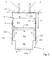
- FIG. 3 shows a further possibility of the arrangement of the positioning element 1 in Ab rehabilitationlement 2.
- the positioning element 1 is arranged below the construction element 3, so that the bottom portion 3.2 of the construction element 3 against the top surface 1.1.2 of the positioning element 1 is applied.
- a positioning element 1 in an arrangement according to the invention is described in more detail below.
- a plurality of suspension elements 2 are fixed to a ceiling 6 or a roof truss substructure in a row in alignment with screws 7, for example.
- the construction element 3 is introduced into the receiving area 2.1 of the respective suspension elements 2, wherein this construction element 3 is secured to at least two suspension elements 2 by means of the positioning element 1 against falling out of the suspension element 2.
- this construction element 3 may be necessary to fix this construction element 3 to at least one additional additional suspension element 2, in order to prevent a bending of the construction element 3.
- the positioning element 1 are arranged above the construction element 3, so that this construction element 3 is fixed on the magnet 5 or the positioning element 1 is arranged below the construction element 3 and this rests on the positioning element 1.
- the alignment of the same takes place, for example, at a reference plane which is predetermined by a leveling laser.
- the construction element 3, which is held punctiform by the positioning elements 1 are displaced within the suspension elements 2.
- the construction element 3 is fastened by laterally inserted into the legs 2.2, 2.2 'of the suspension element 2 screws.
- the positioning elements 1 can be detached from the suspension elements 2 or the construction element 3 and removed.
- these projections can be eliminated, for example by bending the legs 2.2, 2.2 'to the outside or by separating the supernatants.
- consecutively spaced construction elements 3 can be arranged aligned with low personnel costs at a reference plane.
- the production of the positioning element 1 can be made of steel, light metal or plastic.
- the side surfaces 1.1.1, 1.1.1' of the positioning element 1 are preferably designed to be slidable. This can be done for example by a special sliding coating or by polishing the two side surfaces 1.1.1, 1.1.1 '.
- this scaling is provided on the example T-shaped end faces, so that this scale is visible even after introduction of the positioning element 1 in the construction element 3.
Landscapes
- Engineering & Computer Science (AREA)
- Architecture (AREA)
- Civil Engineering (AREA)
- Structural Engineering (AREA)
- Physics & Mathematics (AREA)
- Electromagnetism (AREA)
- Conveying And Assembling Of Building Elements In Situ (AREA)
- Floor Finish (AREA)
Claims (11)
- Agencement destiné au positionnement d'éléments de construction suspendus en pose à sec, composé d'au moins un élément suspendu métallique (2) avec une zone de réception (2.1) et un élément de construction métallique (3), sachant que l'élément suspendu (2) est en U avec deux branches (2.2, 2.2') parallèles entre elles, et un élément de positionnement (1) avec des moyens magnétiques (4, 5) pouvant être intégré dans la zone de réception (2.1) est attribué à l'élément suspendu (2), et les forces magnétiques exercées par les moyens magnétiques (4, 5) agissent sur les branches (2.2, 2.2') de l'élément suspendu (2) ou sur les branches (2.2, 2.2') de l'élément suspendu (2) et l'élément de construction (3) de telle façon que l'élément de construction (3) peut être fixé de façon mobile par rapport à l'élément suspendu (2), au moyen de l'élément de positionnement (1), caractérisé en ce que l'élément de construction (3) métallique est reçu dans la zone de réception (2.1) des éléments suspendus (2) et la zone comprise par les branches (2.2, 2.2') forme la zone de réception (2.1) pour l'élément de construction (3).
- Agencement selon la revendication 1, caractérisé en ce que l'élément de construction (3) est un élément profilé en U ou essentiellement en U, dont la largeur (bP) correspond sur mesure à la largeur (bA) de la zone de réception (2.1) de l'élément suspendu (2).
- Agencement selon la revendication 2, caractérisé en ce que l'élément de construction (3) est disposé de telle façon dans l'élément suspendu (2) que l'élément de construction (3) et l'élément suspendu (2) ouvrent dans des directions opposées.
- Agencement selon l'une des revendications précédentes, caractérisé en ce que l'élément de positionnement (1) présente une première zone d'élément de positionnement (1.1), qui est adaptée sur mesure à la largeur (bA) de la zone de réception (2.1) de l'élément suspendu (2).
- Agencement selon la revendication 4, caractérisé en ce que l'élément de positionnement (1) présente une seconde zone de positionnement (1.2) qui présente une largeur plus étroite que la première zone d'élément de positionnement (1.1).
- Agencement selon la revendication 5, caractérisé en ce que l'élément de positionnement (1) présente au moins un aimant (4) dans la première zone d'élément de positionnement (1.1) qui est ainsi conçu et/ou positionné que l'élément de positionnement (1) disposé dans la zone de réception (2.1) est maintenu par les forces magnétiques agissant sur les branches (2.2, 2.2') de l'élément suspendu (2).
- Agencement selon la revendication 5, caractérisé en ce que l'élément de positionnement (1) présente au moins un aimant (5) dans la seconde zone de positionnement (1.2) qui est ainsi conçu et/ou positionné que l'élément de construction (3) appuyé contre la zone d'élément de positionnement (1.2) est maintenu par les forces magnétiques.
- Agencement selon l'une des revendications précédentes, caractérisé en ce que l'élément de positionnement (1) est reçu à l'intérieur de l'espace de réception délimité sur le pourtour par l'élément suspendu (2) et l'élément de construction (3).
- Agencement selon l'une des revendications précédentes, caractérisé en ce que l'élément de positionnement (1) est disposé en-dessous de l'espace de réception délimité sur le pourtour par l'élément suspendu (2) et l'élément de construction (3), et l'élément de construction (3) repose sur l'élément de positionnement (1).
- Agencement selon l'une des revendications précédentes, comprenant un élément de positionnement destiné à être utilisé dans cet agencement, sachant que l'élément de positionnement est caractérisé par une première zone d'élément de positionnement (1.1) adaptée à la largeur (bA) de la zone de réception (2.1) et une seconde zone d'élément de positionnement (1.2), sachant que tant dans la première que dans la seconde zone d'élément de positionnement (1.1, 1.2), des aimants sont prévus pour l'action conjointe de l'élément suspendu (2) ou de l'élément suspendu et de l'élément de construction (3).
- Agencement selon l'une des revendications précédentes, comprenant un élément de positionnement selon la revendication 10, dans lequel l'élément de positionnement est caractérisé en ce que la seconde zone d'élément de positionnement (1.2) présente une largeur plus étroite que la première zone d'élément de positionnement (1.1).
Applications Claiming Priority (2)
| Application Number | Priority Date | Filing Date | Title |
|---|---|---|---|
| DE202009015143U DE202009015143U1 (de) | 2009-11-06 | 2009-11-06 | Anordnung zur Positionierung von abgehängten Profilen im Trockenbau |
| PCT/DE2010/001140 WO2011054327A2 (fr) | 2009-11-06 | 2010-09-24 | Système de positionnement de profilés suspendus en pose à sec |
Publications (2)
| Publication Number | Publication Date |
|---|---|
| EP2496777A2 EP2496777A2 (fr) | 2012-09-12 |
| EP2496777B1 true EP2496777B1 (fr) | 2015-08-19 |
Family
ID=42035362
Family Applications (1)
| Application Number | Title | Priority Date | Filing Date |
|---|---|---|---|
| EP10781589.6A Active EP2496777B1 (fr) | 2009-11-06 | 2010-09-24 | Système de positionnement de profilés suspendus en pose à sec |
Country Status (4)
| Country | Link |
|---|---|
| US (1) | US20120256063A1 (fr) |
| EP (1) | EP2496777B1 (fr) |
| DE (2) | DE202009015143U1 (fr) |
| WO (1) | WO2011054327A2 (fr) |
Cited By (1)
| Publication number | Priority date | Publication date | Assignee | Title |
|---|---|---|---|---|
| DE102025142274A1 (de) | 2024-10-16 | 2026-04-16 | Wolfcraft Gmbh | Laserzielscheibe zur Positionierung von an eine Tragstruktur zu befestigenden Metallprofilen |
Families Citing this family (4)
| Publication number | Priority date | Publication date | Assignee | Title |
|---|---|---|---|---|
| DE102012006146B4 (de) * | 2012-03-28 | 2017-11-30 | STADUR-Süd-GmbH | Einrichtung zur Befestigung eines Innendämmsystems |
| DE202013103295U1 (de) | 2013-07-23 | 2013-09-16 | Rupert Biller | Montagehilfe |
| CN114150832A (zh) * | 2021-11-17 | 2022-03-08 | 浙江亚厦装饰股份有限公司 | 一种龙骨安装调节结构 |
| EP4467743A1 (fr) * | 2023-05-26 | 2024-11-27 | RM tools, UAB (LTD) | Dispositif d'écartement pour la fixation de profilés métalliques |
Family Cites Families (18)
| Publication number | Priority date | Publication date | Assignee | Title |
|---|---|---|---|---|
| NL285813A (fr) * | 1900-01-01 | |||
| US3292328A (en) * | 1962-06-08 | 1966-12-20 | Stanley T Lewis | Self-supporting panel partition with magnetic latch means therefor |
| US3246074A (en) * | 1963-08-12 | 1966-04-12 | Lightolier Inc | Recessed mount for electric power distribution track |
| GB1056797A (en) * | 1963-10-08 | 1967-01-25 | John Wright And Sons Veneers L | Securing panelling magnetically |
| US3378970A (en) * | 1966-03-18 | 1968-04-23 | Hupp Corp | Wall construction |
| US3852935A (en) * | 1972-09-22 | 1974-12-10 | H Jones | Magnetic wall stud |
| US4014071A (en) * | 1975-09-29 | 1977-03-29 | Janson Richard W | Curtain suspension assembly |
| US4564165A (en) * | 1983-03-31 | 1986-01-14 | Hallmark Cards, Inc. | Attaching device |
| US5381991A (en) * | 1992-02-21 | 1995-01-17 | Sign-Up, Inc. | Suspended display holder |
| AU6838696A (en) * | 1995-09-04 | 1997-03-27 | Kabushikikaisha Asano Seiki | Suspend-supporting method and metal suspender |
| US6393772B1 (en) * | 1999-07-27 | 2002-05-28 | Modernfold, Inc. | Movable wall panel system with self-plumbing panels |
| US6298623B1 (en) * | 2000-06-09 | 2001-10-09 | Usg Interiors, Inc. | Adjustable trim strip system |
| US6644617B2 (en) * | 2000-12-06 | 2003-11-11 | Nelson Douglas Pitlor | Remotely attachable and separable coupling |
| DE10161190A1 (de) * | 2001-12-13 | 2003-06-18 | Fischer Artur Werke Gmbh | Knotenverbinder zum Befestigen von Montageschienen |
| EP1489241A1 (fr) * | 2003-06-20 | 2004-12-22 | Schneider Dämmtechnik AG | Système de fixation pour éléments de plafonds |
| DE102004006211B4 (de) * | 2004-02-09 | 2006-01-26 | Hilti Ag | Verbindungsvorrichtung |
| US7743541B2 (en) * | 2007-02-26 | 2010-06-29 | Rose Displays Ltd | Sign holding extrusion arrangement |
| US7712239B2 (en) * | 2007-08-29 | 2010-05-11 | Rose Displays, Ltd. | Overhead adjustable track support arrangement |
-
2009
- 2009-11-06 DE DE202009015143U patent/DE202009015143U1/de not_active Expired - Lifetime
-
2010
- 2010-09-24 US US13/508,144 patent/US20120256063A1/en not_active Abandoned
- 2010-09-24 WO PCT/DE2010/001140 patent/WO2011054327A2/fr not_active Ceased
- 2010-09-24 EP EP10781589.6A patent/EP2496777B1/fr active Active
- 2010-09-24 DE DE112010004311T patent/DE112010004311A5/de not_active Withdrawn
Cited By (2)
| Publication number | Priority date | Publication date | Assignee | Title |
|---|---|---|---|---|
| DE102025142274A1 (de) | 2024-10-16 | 2026-04-16 | Wolfcraft Gmbh | Laserzielscheibe zur Positionierung von an eine Tragstruktur zu befestigenden Metallprofilen |
| WO2026082855A1 (fr) | 2024-10-16 | 2026-04-23 | Wolfcraft Gmbh | Cible laser pour positionner des profilés métalliques à fixer à une structure de support |
Also Published As
| Publication number | Publication date |
|---|---|
| WO2011054327A3 (fr) | 2012-07-26 |
| EP2496777A2 (fr) | 2012-09-12 |
| US20120256063A1 (en) | 2012-10-11 |
| DE202009015143U1 (de) | 2010-03-18 |
| DE112010004311A5 (de) | 2013-01-03 |
| WO2011054327A2 (fr) | 2011-05-12 |
Similar Documents
| Publication | Publication Date | Title |
|---|---|---|
| EP0531869B1 (fr) | Pince de montage | |
| AT518814B1 (de) | Zaunsystem sowie Montageverfahren für ein Zaunsystem | |
| EP2446096B1 (fr) | Support d`angle pour système de façade | |
| EP2943625B1 (fr) | Cloison sèche | |
| EP3235983A1 (fr) | Installation de porte coulissante et systeme a rails | |
| EP3548412B1 (fr) | Dispositif de fixation et procédé permettant de fixer un élément de paroi dans une cabine d'ascenseur | |
| EP3365510B1 (fr) | Système destiné à l'habillage de murs, plafonds ou toits d'un corps de bâtiment | |
| WO2011054327A2 (fr) | Système de positionnement de profilés suspendus en pose à sec | |
| EP3636844B1 (fr) | Cadre de construction en mur sec pour une porte coulissante | |
| DE202014105882U1 (de) | Anordnung zur Verbindung von Bauteilen, insbesondere von zwei Bauteilen einer Unterkonstruktion, insbesondere für Balkon- und Terrassenabdeckungen | |
| DE202011100168U1 (de) | Befestigungswinkel für die Unterkonstruktion von vorgehängten Fassaden und Montagesystem umfassend wenigstens einen solchen Befestigungswinkel | |
| EP3091133B1 (fr) | Système de retenue pour éléments de paroi | |
| EP3103956A1 (fr) | Profile porteur modulaire comprenant des logements de barres | |
| DE10134396C1 (de) | Bausatz zum Einsetzen eines Wandelementes in eine Wandöffnung einer doppelschaligen Ständerwand | |
| DE10329717A1 (de) | Freistanddach | |
| DE202014000971U1 (de) | Profilsystem für Verglasungen | |
| DE102005044322B4 (de) | Haltekonstruktion für Fassadenplatten, sowie Gebäudefassade | |
| DE112017003921T5 (de) | Verankerungsvorrichtung für belüftete Vorhangfassaden | |
| DE102017125674B4 (de) | Haltevorrichtung für ein Flächenelement, Absturzsicherung und französischer Balkon | |
| EP3296475B1 (fr) | Balcon et procédé de fabrication d'un tel balcon | |
| DE4204638A1 (de) | Vorrichtung zur schalldaemmung in raeumen | |
| DE202013103663U1 (de) | Einbaurahmen für Schiebetüren | |
| DE19945886C1 (de) | Langgestrecktes Halterprofil einer Fassaden-Unterkonstruktion | |
| DE102017008020A1 (de) | Modulare Wand | |
| DE102019116533B4 (de) | Deckenanordnung |
Legal Events
| Date | Code | Title | Description |
|---|---|---|---|
| PUAI | Public reference made under article 153(3) epc to a published international application that has entered the european phase |
Free format text: ORIGINAL CODE: 0009012 |
|
| 17P | Request for examination filed |
Effective date: 20120521 |
|
| AK | Designated contracting states |
Kind code of ref document: A2 Designated state(s): AL AT BE BG CH CY CZ DE DK EE ES FI FR GB GR HR HU IE IS IT LI LT LU LV MC MK MT NL NO PL PT RO SE SI SK SM TR |
|
| DAX | Request for extension of the european patent (deleted) | ||
| GRAP | Despatch of communication of intention to grant a patent |
Free format text: ORIGINAL CODE: EPIDOSNIGR1 |
|
| INTG | Intention to grant announced |
Effective date: 20150323 |
|
| GRAS | Grant fee paid |
Free format text: ORIGINAL CODE: EPIDOSNIGR3 |
|
| GRAA | (expected) grant |
Free format text: ORIGINAL CODE: 0009210 |
|
| AK | Designated contracting states |
Kind code of ref document: B1 Designated state(s): AL AT BE BG CH CY CZ DE DK EE ES FI FR GB GR HR HU IE IS IT LI LT LU LV MC MK MT NL NO PL PT RO SE SI SK SM TR |
|
| REG | Reference to a national code |
Ref country code: GB Ref legal event code: FG4D Free format text: NOT ENGLISH |
|
| REG | Reference to a national code |
Ref country code: CH Ref legal event code: EP Ref country code: CH Ref legal event code: NV Representative=s name: MICHELI AND CIE SA, CH |
|
| REG | Reference to a national code |
Ref country code: IE Ref legal event code: FG4D Free format text: LANGUAGE OF EP DOCUMENT: GERMAN |
|
| REG | Reference to a national code |
Ref country code: AT Ref legal event code: REF Ref document number: 743946 Country of ref document: AT Kind code of ref document: T Effective date: 20150915 |
|
| REG | Reference to a national code |
Ref country code: DE Ref legal event code: R096 Ref document number: 502010010118 Country of ref document: DE |
|
| REG | Reference to a national code |
Ref country code: LT Ref legal event code: MG4D |
|
| REG | Reference to a national code |
Ref country code: NL Ref legal event code: MP Effective date: 20150819 |
|
| PG25 | Lapsed in a contracting state [announced via postgrant information from national office to epo] |
Ref country code: NO Free format text: LAPSE BECAUSE OF FAILURE TO SUBMIT A TRANSLATION OF THE DESCRIPTION OR TO PAY THE FEE WITHIN THE PRESCRIBED TIME-LIMIT Effective date: 20151119 Ref country code: LT Free format text: LAPSE BECAUSE OF FAILURE TO SUBMIT A TRANSLATION OF THE DESCRIPTION OR TO PAY THE FEE WITHIN THE PRESCRIBED TIME-LIMIT Effective date: 20150819 Ref country code: GR Free format text: LAPSE BECAUSE OF FAILURE TO SUBMIT A TRANSLATION OF THE DESCRIPTION OR TO PAY THE FEE WITHIN THE PRESCRIBED TIME-LIMIT Effective date: 20151120 Ref country code: LV Free format text: LAPSE BECAUSE OF FAILURE TO SUBMIT A TRANSLATION OF THE DESCRIPTION OR TO PAY THE FEE WITHIN THE PRESCRIBED TIME-LIMIT Effective date: 20150819 Ref country code: FI Free format text: LAPSE BECAUSE OF FAILURE TO SUBMIT A TRANSLATION OF THE DESCRIPTION OR TO PAY THE FEE WITHIN THE PRESCRIBED TIME-LIMIT Effective date: 20150819 |
|
| PG25 | Lapsed in a contracting state [announced via postgrant information from national office to epo] |
Ref country code: SE Free format text: LAPSE BECAUSE OF FAILURE TO SUBMIT A TRANSLATION OF THE DESCRIPTION OR TO PAY THE FEE WITHIN THE PRESCRIBED TIME-LIMIT Effective date: 20150819 Ref country code: ES Free format text: LAPSE BECAUSE OF FAILURE TO SUBMIT A TRANSLATION OF THE DESCRIPTION OR TO PAY THE FEE WITHIN THE PRESCRIBED TIME-LIMIT Effective date: 20150819 Ref country code: PL Free format text: LAPSE BECAUSE OF FAILURE TO SUBMIT A TRANSLATION OF THE DESCRIPTION OR TO PAY THE FEE WITHIN THE PRESCRIBED TIME-LIMIT Effective date: 20150819 Ref country code: PT Free format text: LAPSE BECAUSE OF FAILURE TO SUBMIT A TRANSLATION OF THE DESCRIPTION OR TO PAY THE FEE WITHIN THE PRESCRIBED TIME-LIMIT Effective date: 20151221 Ref country code: IS Free format text: LAPSE BECAUSE OF FAILURE TO SUBMIT A TRANSLATION OF THE DESCRIPTION OR TO PAY THE FEE WITHIN THE PRESCRIBED TIME-LIMIT Effective date: 20151219 |
|
| PG25 | Lapsed in a contracting state [announced via postgrant information from national office to epo] |
Ref country code: NL Free format text: LAPSE BECAUSE OF FAILURE TO SUBMIT A TRANSLATION OF THE DESCRIPTION OR TO PAY THE FEE WITHIN THE PRESCRIBED TIME-LIMIT Effective date: 20150819 |
|
| PG25 | Lapsed in a contracting state [announced via postgrant information from national office to epo] |
Ref country code: EE Free format text: LAPSE BECAUSE OF FAILURE TO SUBMIT A TRANSLATION OF THE DESCRIPTION OR TO PAY THE FEE WITHIN THE PRESCRIBED TIME-LIMIT Effective date: 20150819 Ref country code: DK Free format text: LAPSE BECAUSE OF FAILURE TO SUBMIT A TRANSLATION OF THE DESCRIPTION OR TO PAY THE FEE WITHIN THE PRESCRIBED TIME-LIMIT Effective date: 20150819 Ref country code: CZ Free format text: LAPSE BECAUSE OF FAILURE TO SUBMIT A TRANSLATION OF THE DESCRIPTION OR TO PAY THE FEE WITHIN THE PRESCRIBED TIME-LIMIT Effective date: 20150819 Ref country code: SK Free format text: LAPSE BECAUSE OF FAILURE TO SUBMIT A TRANSLATION OF THE DESCRIPTION OR TO PAY THE FEE WITHIN THE PRESCRIBED TIME-LIMIT Effective date: 20150819 Ref country code: IT Free format text: LAPSE BECAUSE OF FAILURE TO SUBMIT A TRANSLATION OF THE DESCRIPTION OR TO PAY THE FEE WITHIN THE PRESCRIBED TIME-LIMIT Effective date: 20150819 |
|
| REG | Reference to a national code |
Ref country code: DE Ref legal event code: R097 Ref document number: 502010010118 Country of ref document: DE |
|
| PG25 | Lapsed in a contracting state [announced via postgrant information from national office to epo] |
Ref country code: RO Free format text: LAPSE BECAUSE OF FAILURE TO SUBMIT A TRANSLATION OF THE DESCRIPTION OR TO PAY THE FEE WITHIN THE PRESCRIBED TIME-LIMIT Effective date: 20150819 Ref country code: MC Free format text: LAPSE BECAUSE OF FAILURE TO SUBMIT A TRANSLATION OF THE DESCRIPTION OR TO PAY THE FEE WITHIN THE PRESCRIBED TIME-LIMIT Effective date: 20150819 |
|
| PLBE | No opposition filed within time limit |
Free format text: ORIGINAL CODE: 0009261 |
|
| STAA | Information on the status of an ep patent application or granted ep patent |
Free format text: STATUS: NO OPPOSITION FILED WITHIN TIME LIMIT |
|
| REG | Reference to a national code |
Ref country code: IE Ref legal event code: MM4A |
|
| 26N | No opposition filed |
Effective date: 20160520 |
|
| PG25 | Lapsed in a contracting state [announced via postgrant information from national office to epo] |
Ref country code: IE Free format text: LAPSE BECAUSE OF NON-PAYMENT OF DUE FEES Effective date: 20150924 |
|
| PG25 | Lapsed in a contracting state [announced via postgrant information from national office to epo] |
Ref country code: SI Free format text: LAPSE BECAUSE OF FAILURE TO SUBMIT A TRANSLATION OF THE DESCRIPTION OR TO PAY THE FEE WITHIN THE PRESCRIBED TIME-LIMIT Effective date: 20150819 |
|
| REG | Reference to a national code |
Ref country code: FR Ref legal event code: PLFP Year of fee payment: 7 |
|
| PG25 | Lapsed in a contracting state [announced via postgrant information from national office to epo] |
Ref country code: MT Free format text: LAPSE BECAUSE OF FAILURE TO SUBMIT A TRANSLATION OF THE DESCRIPTION OR TO PAY THE FEE WITHIN THE PRESCRIBED TIME-LIMIT Effective date: 20150819 |
|
| PG25 | Lapsed in a contracting state [announced via postgrant information from national office to epo] |
Ref country code: HU Free format text: LAPSE BECAUSE OF FAILURE TO SUBMIT A TRANSLATION OF THE DESCRIPTION OR TO PAY THE FEE WITHIN THE PRESCRIBED TIME-LIMIT; INVALID AB INITIO Effective date: 20100924 Ref country code: BG Free format text: LAPSE BECAUSE OF FAILURE TO SUBMIT A TRANSLATION OF THE DESCRIPTION OR TO PAY THE FEE WITHIN THE PRESCRIBED TIME-LIMIT Effective date: 20150819 Ref country code: SM Free format text: LAPSE BECAUSE OF FAILURE TO SUBMIT A TRANSLATION OF THE DESCRIPTION OR TO PAY THE FEE WITHIN THE PRESCRIBED TIME-LIMIT Effective date: 20150819 |
|
| PG25 | Lapsed in a contracting state [announced via postgrant information from national office to epo] |
Ref country code: CY Free format text: LAPSE BECAUSE OF FAILURE TO SUBMIT A TRANSLATION OF THE DESCRIPTION OR TO PAY THE FEE WITHIN THE PRESCRIBED TIME-LIMIT Effective date: 20150819 |
|
| PG25 | Lapsed in a contracting state [announced via postgrant information from national office to epo] |
Ref country code: HR Free format text: LAPSE BECAUSE OF FAILURE TO SUBMIT A TRANSLATION OF THE DESCRIPTION OR TO PAY THE FEE WITHIN THE PRESCRIBED TIME-LIMIT Effective date: 20150819 Ref country code: BE Free format text: LAPSE BECAUSE OF NON-PAYMENT OF DUE FEES Effective date: 20150930 |
|
| PG25 | Lapsed in a contracting state [announced via postgrant information from national office to epo] |
Ref country code: TR Free format text: LAPSE BECAUSE OF FAILURE TO SUBMIT A TRANSLATION OF THE DESCRIPTION OR TO PAY THE FEE WITHIN THE PRESCRIBED TIME-LIMIT Effective date: 20150819 |
|
| REG | Reference to a national code |
Ref country code: FR Ref legal event code: PLFP Year of fee payment: 8 |
|
| PG25 | Lapsed in a contracting state [announced via postgrant information from national office to epo] |
Ref country code: LU Free format text: LAPSE BECAUSE OF NON-PAYMENT OF DUE FEES Effective date: 20150924 |
|
| PG25 | Lapsed in a contracting state [announced via postgrant information from national office to epo] |
Ref country code: MK Free format text: LAPSE BECAUSE OF FAILURE TO SUBMIT A TRANSLATION OF THE DESCRIPTION OR TO PAY THE FEE WITHIN THE PRESCRIBED TIME-LIMIT Effective date: 20150819 |
|
| REG | Reference to a national code |
Ref country code: FR Ref legal event code: PLFP Year of fee payment: 9 |
|
| PG25 | Lapsed in a contracting state [announced via postgrant information from national office to epo] |
Ref country code: AL Free format text: LAPSE BECAUSE OF FAILURE TO SUBMIT A TRANSLATION OF THE DESCRIPTION OR TO PAY THE FEE WITHIN THE PRESCRIBED TIME-LIMIT Effective date: 20150819 |
|
| PGFP | Annual fee paid to national office [announced via postgrant information from national office to epo] |
Ref country code: FR Payment date: 20190927 Year of fee payment: 10 |
|
| PGFP | Annual fee paid to national office [announced via postgrant information from national office to epo] |
Ref country code: GB Payment date: 20190920 Year of fee payment: 10 Ref country code: AT Payment date: 20190919 Year of fee payment: 10 |
|
| PGFP | Annual fee paid to national office [announced via postgrant information from national office to epo] |
Ref country code: CH Payment date: 20190919 Year of fee payment: 10 |
|
| REG | Reference to a national code |
Ref country code: CH Ref legal event code: PL |
|
| REG | Reference to a national code |
Ref country code: AT Ref legal event code: MM01 Ref document number: 743946 Country of ref document: AT Kind code of ref document: T Effective date: 20200924 |
|
| GBPC | Gb: european patent ceased through non-payment of renewal fee |
Effective date: 20200924 |
|
| PG25 | Lapsed in a contracting state [announced via postgrant information from national office to epo] |
Ref country code: FR Free format text: LAPSE BECAUSE OF NON-PAYMENT OF DUE FEES Effective date: 20200930 |
|
| PG25 | Lapsed in a contracting state [announced via postgrant information from national office to epo] |
Ref country code: AT Free format text: LAPSE BECAUSE OF NON-PAYMENT OF DUE FEES Effective date: 20200924 Ref country code: CH Free format text: LAPSE BECAUSE OF NON-PAYMENT OF DUE FEES Effective date: 20200930 Ref country code: GB Free format text: LAPSE BECAUSE OF NON-PAYMENT OF DUE FEES Effective date: 20200924 Ref country code: LI Free format text: LAPSE BECAUSE OF NON-PAYMENT OF DUE FEES Effective date: 20200930 |
|
| PGFP | Annual fee paid to national office [announced via postgrant information from national office to epo] |
Ref country code: DE Payment date: 20250930 Year of fee payment: 16 |