EP2497435A2 - Vis de pédicule polyaxial à angulation accrue - Google Patents
Vis de pédicule polyaxial à angulation accrue Download PDFInfo
- Publication number
- EP2497435A2 EP2497435A2 EP12001589A EP12001589A EP2497435A2 EP 2497435 A2 EP2497435 A2 EP 2497435A2 EP 12001589 A EP12001589 A EP 12001589A EP 12001589 A EP12001589 A EP 12001589A EP 2497435 A2 EP2497435 A2 EP 2497435A2
- Authority
- EP
- European Patent Office
- Prior art keywords
- housing
- angulation
- bore
- degrees
- bone anchor
- Prior art date
- Legal status (The legal status is an assumption and is not a legal conclusion. Google has not performed a legal analysis and makes no representation as to the accuracy of the status listed.)
- Granted
Links
- 210000000988 bone and bone Anatomy 0.000 claims abstract description 108
- 230000006641 stabilisation Effects 0.000 claims description 12
- 238000011105 stabilization Methods 0.000 claims description 12
- 238000000034 method Methods 0.000 claims description 10
- 230000000295 complement effect Effects 0.000 description 6
- 210000002517 zygapophyseal joint Anatomy 0.000 description 3
- 238000010276 construction Methods 0.000 description 2
- 238000012986 modification Methods 0.000 description 2
- 230000004048 modification Effects 0.000 description 2
- 230000000712 assembly Effects 0.000 description 1
- 238000000429 assembly Methods 0.000 description 1
- 230000000694 effects Effects 0.000 description 1
- 230000004927 fusion Effects 0.000 description 1
- 230000001771 impaired effect Effects 0.000 description 1
- 238000004519 manufacturing process Methods 0.000 description 1
- 239000000463 material Substances 0.000 description 1
- 230000000399 orthopedic effect Effects 0.000 description 1
- 238000001356 surgical procedure Methods 0.000 description 1
Images









Classifications
-
- A—HUMAN NECESSITIES
- A61—MEDICAL OR VETERINARY SCIENCE; HYGIENE
- A61B—DIAGNOSIS; SURGERY; IDENTIFICATION
- A61B17/00—Surgical instruments, devices or methods
- A61B17/56—Surgical instruments or methods for treatment of bones or joints; Devices specially adapted therefor
- A61B17/58—Surgical instruments or methods for treatment of bones or joints; Devices specially adapted therefor for osteosynthesis, e.g. bone plates, screws or setting implements
- A61B17/68—Internal fixation devices, including fasteners and spinal fixators, even if a part thereof projects from the skin
- A61B17/70—Spinal positioners or stabilisers, e.g. stabilisers comprising fluid filler in an implant
- A61B17/7001—Screws or hooks combined with longitudinal elements which do not contact vertebrae
- A61B17/7035—Screws or hooks, wherein a rod-clamping part and a bone-anchoring part can pivot relative to each other
- A61B17/7038—Screws or hooks, wherein a rod-clamping part and a bone-anchoring part can pivot relative to each other to a different extent in different directions, e.g. within one plane only
-
- A—HUMAN NECESSITIES
- A61—MEDICAL OR VETERINARY SCIENCE; HYGIENE
- A61B—DIAGNOSIS; SURGERY; IDENTIFICATION
- A61B17/00—Surgical instruments, devices or methods
- A61B17/56—Surgical instruments or methods for treatment of bones or joints; Devices specially adapted therefor
- A61B17/58—Surgical instruments or methods for treatment of bones or joints; Devices specially adapted therefor for osteosynthesis, e.g. bone plates, screws or setting implements
- A61B17/68—Internal fixation devices, including fasteners and spinal fixators, even if a part thereof projects from the skin
- A61B17/70—Spinal positioners or stabilisers, e.g. stabilisers comprising fluid filler in an implant
- A61B17/7001—Screws or hooks combined with longitudinal elements which do not contact vertebrae
- A61B17/7032—Screws or hooks with U-shaped head or back through which longitudinal rods pass
-
- A—HUMAN NECESSITIES
- A61—MEDICAL OR VETERINARY SCIENCE; HYGIENE
- A61B—DIAGNOSIS; SURGERY; IDENTIFICATION
- A61B17/00—Surgical instruments, devices or methods
- A61B17/56—Surgical instruments or methods for treatment of bones or joints; Devices specially adapted therefor
- A61B17/58—Surgical instruments or methods for treatment of bones or joints; Devices specially adapted therefor for osteosynthesis, e.g. bone plates, screws or setting implements
- A61B17/68—Internal fixation devices, including fasteners and spinal fixators, even if a part thereof projects from the skin
- A61B17/70—Spinal positioners or stabilisers, e.g. stabilisers comprising fluid filler in an implant
- A61B17/7001—Screws or hooks combined with longitudinal elements which do not contact vertebrae
- A61B17/7035—Screws or hooks, wherein a rod-clamping part and a bone-anchoring part can pivot relative to each other
- A61B17/7037—Screws or hooks, wherein a rod-clamping part and a bone-anchoring part can pivot relative to each other wherein pivoting is blocked when the rod is clamped
-
- Y—GENERAL TAGGING OF NEW TECHNOLOGICAL DEVELOPMENTS; GENERAL TAGGING OF CROSS-SECTIONAL TECHNOLOGIES SPANNING OVER SEVERAL SECTIONS OF THE IPC; TECHNICAL SUBJECTS COVERED BY FORMER USPC CROSS-REFERENCE ART COLLECTIONS [XRACs] AND DIGESTS
- Y10—TECHNICAL SUBJECTS COVERED BY FORMER USPC
- Y10T—TECHNICAL SUBJECTS COVERED BY FORMER US CLASSIFICATION
- Y10T29/00—Metal working
- Y10T29/49—Method of mechanical manufacture
- Y10T29/49826—Assembling or joining
- Y10T29/49863—Assembling or joining with prestressing of part
Definitions
- the disclosure is directed to vertebral anchors for use with orthopedic fixation systems. More particularly, the disclosure is directed to polyaxial bone anchors including structures for controlling the angulation limit of a bone screw as a function of direction.
- the spinal column of a patient includes a plurality of vertebrae linked to one another by facet joints and an intervertebral disc located between adjacent vertebrae.
- the facet joints and intervertebral disc allow one vertebra to move relative to an adjacent vertebra, providing the spinal column a range of motion.
- Diseased, degenerated, damaged, or otherwise impaired facet joints and/or intervertebral discs may cause the patient to experience pain or discomfort and/or loss of motion, thus prompting surgery to alleviate the pain and/or restore motion of the spinal column.
- One possible method of treating these conditions is to immobilize a portion of the spine to allow treatment.
- immobilization has been accomplished by rigid stabilization.
- a surgeon restores the alignment of the spine or the disc space between vertebrae by installing a rigid fixation rod between pedicle screws secured to adjacent vertebrae. Bone graft is placed between the vertebrae, and the fixation rod cooperates with the screws to immobilize the two vertebrae relative to each other so that the bone graft may fuse with the vertebrae.
- Dynamic stabilization has also been used in spinal treatment procedures. Dynamic stabilization does not result in complete immobilization, but instead permits a degree of mobility of the spine while also providing sufficient support and stabilization to effect treatment.
- a dynamic stabilization system is the Dynesys® system available from Zimmer Spine, Inc. of Minneapolis, MN. Such dynamic stabilization systems typically include a flexible construct extending between pedicle screws installed in adjacent vertebrae of the spine.
- an anchor that provides a relatively large angulation (i.e., the angle at which the bone screw is tilted with respect to a longitudinal axis of the anchor housing) over a continuous range of azimuthal angles around the longitudinal axis of the anchor housing.
- the disclosure is directed to several alternative designs, materials and methods of assembling polyaxial bone anchor structures and assemblies.
- the polyaxial bone anchor includes a housing and a bone screw.
- the housing has an upper end, a lower end and a bore extending through the housing from the upper end to the lower end.
- the bore opens out at the lower end at a lower opening.
- the housing includes a channel configured for receiving an elongate stabilization member therethrough.
- the elongate stabilization member extends from a first side surface of the housing to a second side surface of the housing opposite the first side surface transverse to the bore.
- the bone screw includes a head and a shank extending from the head. The head of the bone screw is positionable in the housing. The shank extends from the lower end of the housing.
- the lower opening of the bore defines an angulation limit of the bone screw for each azimuthal angle around a longitudinal axis of the bore.
- the lower opening of the bore is generally V-shaped.
- the V-shape has angled side walls. The angled side walls define a low-angulation direction proximate their intersection and define a high-angulation direction opposite the low-angulation direction.
- the polyaxial bone anchor includes a housing and a bone screw.
- the housing has an upper end, a lower end and a bore extending through the housing from the upper end to the lower end.
- the bore opens out at the lower end at a lower opening.
- the housing includes a channel configured for receiving an elongate stabilization member therethrough.
- the elongate stabilization member extends from a first side surface of the housing to a second side surface of the housing opposite the first side surface transverse to the bore.
- the bone screw includes a head and a shank extending from the head. The head of the bone screw is positionable in the housing. The shank extends from the lower end of the housing.
- the lower opening of the bore defines an angulation limit of the bone screw for each azimuthal angle around a longitudinal axis of the bore.
- the angulation limit has a maximum value in a high-angulation direction.
- the angulation limit is generally constant over an azimuthal range centered about the high-angulation direction. For a low-angulation direction opposite the high-angulation direction, the angulation limit is less than the maximum value.
- Another illustrative embodiment is a method of assembling a polyaxial bone anchor.
- the method includes providing an upper housing having a bore extending vertically therethrough, the upper housing including a plurality of plastically deformable tabs circumferentially around a lower end of the upper housing, each tab having a portion that extends radially outward beyond a radial extent of the bore and a portion that extends radially inside the bore; providing a lower housing having a lip proximate an upper end of the lower housing; placing the lower housing beneath the upper housing so that the lip is radially adjacent the tabs; inserting a mandrel downward through the bore in the upper housing; forcing the tabs radially outward with the mandrel, each tab on the upper housing plastically deforming radially outward and engaging the lip on the lower housing; and withdrawing the mandrel from the upper housing.
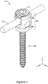
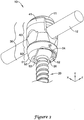
- FIG. 1 is an exploded view illustrating components of an exemplary polyaxial bone anchor 10.
- the bone anchor 10 which may be screwed into a vertebra, may serve to couple a rod 12 or other elongate member extending along a portion of a spinal column.
- the rod or elongate member 12 may fit into a U-shaped channel 43 formed by opposing arms 41 from the top of the housing 30.
- the bone anchor 10 may include particular degrees of adjustability that ensure that the screws and elongate member 12 may be locked down at the particular locations and orientations desired by the practitioner.
- the housing 30 may be adjusted to accommodate the rod 12 in the U-shaped channel 43, in this document we examine the elements from the point of view of the housing 30, so that the screw 20 may be referred to as being adjustable with respect to the housing 30.
- the bone anchor 10 may allow for angular deviation of the bone screw 20 away from the axial orientation shown in FIG. 1 .
- Such an angular deviation may be referred to as "angulation”, and desired angulations may exceed 35 degrees, 40 degrees, 45 degrees, or more, in some instances.
- the bone anchor 10 may allow for angulation in a variety of directions, not just in one direction. These directions are measured with respect to a longitudinal axis of the bone anchor 10, which in FIG. 1 extends from the top to the bottom of the drawing.
- the longitudinal axis may be coaxial with the threaded bore of the housing 30. These directions may be referred to as an "azimuthal angle", and may extend from 0 degrees to 360 degrees around the longitudinal axis of the bone anchor 10.
- the allowed angulation of the bone anchor 10 may vary as a function of azimuthal angle, so that angulation may be more restricted in one direction over another.
- the bone anchor 10 may be configured such that the maximum angulation of the bone screw 20 relative to the longitudinal axis of the housing 30 may be greater at a first azimuthal angle than at a second azimuthal angle.
- angulation limit As a function of azimuthal angle, there is particular attention paid to the amount of angulation that is allowed (referred to herein as an "angulation limit") as a function of azimuthal angle. These aspects of angulation limit versus azimuthal angle are discussed in detail, following a brief discussion of the various elements shown in the exploded view of FIG. 1 , and also shown in the assembled views of FIGS. 2-7 .
- the bone anchor 10 may be delivered to the practitioner in a semi-assembled state.
- the housing 30 may have a bore that extends longitudinally through the housing 30, generally coaxial with the longitudinal axis of the bone anchor 10.
- the housing 30 may be modular, thus formed of multiple components coupled together.
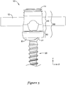
- the housing 30 may include two components that are longitudinally adjacent to each other, namely an upper housing 40 and a lower housing 50.
- the lower housing 50 may be rotatable relative to the upper housing 40, such that the high angular direction 54 (see FIG. 3 ) may be positioned at any desired angular orientation relative to the axis of the U-shaped channel 43 of the upper housing 40.
- the housing 30 may alternatively be of a unitary construction, formed of a singular element.
- the screw 20 Prior to assembly, the screw 20 may be dropped downward into the top of the housing 30. Alternatively, the screw 20 may be bottom-loaded into the upper housing 40, and then the lower housing 50 may be coupled onto the upper housing 40, so that the screw 20 is held in place between the coupled upper housing 40 and lower housing 50.
- the screw 20 may have a threaded shank 23 that extends out the bottom opening of the housing 30, and may have a head 21 that is sized such that the head 21 cannot pass through the opening at the bottom of the housing 30.
- the head 21 of the screw 20 may be generally spherical in shape, so that it may pivot with respect to the housing 30.
- the head 21 of the screw 20 may be held in place by a retainer assembly 13, which may prevent the screw 20 from being pulled upward out of the housing 30.
- the retainer assembly 13 may allow pivoting of the screw head 21 with respect to the housing 30.
- the retainer assembly 13 is typically in the form of one or more rings having a central aperture, which may allow the practitioner to insert a screwdriver through the aperture of the rings to engage a driver interface such as a keyed portion 22 on the head 21 of the screw 20.
- the exemplary retainer assembly 13 in FIG. 1 may include a seat 16 that may contact the head 21 of the screw 20, a biasing member or wave washer 15, and a retainer ring 14 farthest away from the screw head 21.
- the seat 16 may include a concave annular region that has a radius of curvature matched to that of the screw head 21, so that when the screw 20 is pivoted, it may remain held in place by the seat 16.
- the practitioner may screw the fastener or set screw 11 into threads 42 at the upper portion of the housing 30, which may force the rod or elongate member 12 against the upper surface of seat 16, and in turn may force the seat 16 against the head 21 of the screw 20.
- the biasing member 15 Prior to final tightening of the set screw 11, the biasing member 15 may cause the seat 16 to frictionally engage the head 21 of the screw 20 to resist movement of the housing 30 with respect to the screw 20.
- the frictional force between the seat 16 of the retainer assembly 13 and the head 21 of the screw 20 is sufficient to lock the screw 20 in place with respect to the housing 30.
- the U-shaped channel 43 is deep enough so that the set screw 11 does not force the rod 12 against the bottom of the U-shaped channel 43.
- the retainer assembly 13 may be omitted, and the set screw 11 may force the rod 12 directly against the head 21 of the screw 20 to secure the screw 20 in place.
- the housing 30 may have a bottom surface 51 with a shaped opening 56.
- the perimeter of the opening 56 may directly affect how much angulation may be achieved in a given direction, because the shank 23 of the screw 20 beneath the head 21 may engage the perimeter at the angulation limit, preventing further angulation.
- By tailoring the perimeter of the opening 56 one may control the angulation limit as a function of azimuthal angle. Note that one still needs a particular amount of surface area on the bottom surface to engage the head 21 of the screw 20; one cannot simply make the opening 56 arbitrarily large in all directions, because the head 21 of the screw 20 would fall through the opening 56.
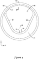
- the opening 56 in the bottom surface 51 may be generally V-shaped, with angled or converging side walls 52.
- the angled side walls 52 At the "closed" end of the V-shape (i.e., the end in which the side walls 52 are closer together), the angled side walls 52 define a low-angulation direction 53.
- the angled side walls 52 Opposite the low-angulation direction 53, at the "open" end of the V-shape (i.e., the end in which the side walls 52 are further apart), the angled side walls 52 define a high-angulation direction 54.
- the low-angulation direction is toward the bottom-left corner of the figure, while the high-angulation direction is toward the top-right corner of the figure.
- the high-angulation direction 54 is at the top of the figure, while the low-angulation direction 53 is at the bottom of the figure.
- the high-angulation direction 54 (at the 12 o'clock position, or 0 degrees) may be opposite (i.e. 180 degrees from) the low-angulation direction 53 (at the 6 o'clock position, or 180 degrees).
- the shape of the opening 56 at the bottom surface 51 of the lower housing 50 may alternatively be described as follows.
- the opening 56 may be defined by converging planar side walls 52, a first arcuate end wall 91 extending between the side walls 52 at a first end 97 proximate the high-angulation direction 54, a second arcuate end wall 93 extending between the side walls 52 at a second end 93 proximate the low-angulation direction 53.
- the arc length of the first arcuate end wall 91 may be greater than the arc length of the second arcuate end wall 93.
- the first arcuate end wall 91 may have a radius of curvature greater than a radius of curvature of the second arcuate end wall 93.
- the screw 20 is pointing directly downward, so that as drawn, it has an angulation of zero.
- the longitudinal axis of the screw 20 is coaxial with the longitudinal axis of the housing 30.
- the screw 20 may pivot a particular amount from the longitudinal axis of the housing 30, such as less than 5 degrees, about 5 degrees, between 5 and 10 degrees, about 10 degrees, between 10 and 15 degrees, about 15 degrees, between 15 and 20 degrees, about 20 degrees, between 20 and 25 degrees, about 25 degrees, between 25 and 30 degrees, less than 30 degrees, less than 25 degrees, less than 20 degrees, less than 15 degrees, less than 10 degrees, or less than 5 degrees, in some instances.
- each of these numerical values or ranges may represent the angulation limit in the low-angulation direction 53.
- the screw 20 may also pivot a particular amount from the longitudinal axis of the housing 30, such as about 30 degrees, more than 30 degrees, about 35 degrees, more than 35 degrees, about 40 degrees, more than 40 degrees, about 45 degrees, more than 45 degrees, about 50 degrees, or more than 50 degrees, in some instances. In some instances, each of these numerical values or ranges may represent the angulation limit in the high-angulation direction 54.
- the angulation limit may be largely determined by the shape of the angled side walls 52.
- the side walls 52 may be relatively straight or planar, may bow inward, may bow outward, or may have a more complicated shape.
- the angulation limit achieves a minimum value at an azimuthal angular position between the high-angulation direction and the low-angulation direction. In other cases, the angulation limit achieves a minimum value at the low-angulation direction.
- the range of azimuthal angles R over which the angulation limit is essentially constant may be greater than 50 degrees, greater than 60 degrees, greater than 70 degrees, greater than 80 degrees, or greater than 90 degrees, in some instances.
- FIGS. 8 and 9 are two exemplary plots of angulation limit as a function of azimuthal angle (in the x-z plane) around a longitudinal axis of the bore of the housing 30.
- the longitudinal axis of the housing 30 lies along the y-axis, with azimuthal angles tracing out 360 degrees in the x-z plane.
- the low-angulation direction 53 is along the negative z-axis (or at 6 o'clock or 180 degrees on the plots)
- the high-angulation direction 54 is along the positive z-axis (or at 12 o'clock or 0 degrees on the plots).
- the angulation limit at the particular azimuthal angle has a value given by the plotted curve.
- FIG. 8 which plots the angulation limits provided by the opening 56 of the housing 30, shows exemplary angulation limit values of 25.3 degrees in the low-angulation direction 53 (6 o'clock or 180 degrees on the plot), 17.3 degrees lateral to the low-angulation direction 53 (3 o'clock or 90 degrees and 9 o'clock or 270 degrees on the plot), and 47.5 degrees in the high-angulation direction 54 (12 o'clock or 0 degrees on the plot).
- the angulation limit is essentially constant over a range of azimuthal angles R of 87 degrees centered about the high-angulation direction 54, corresponding to the ridge 55 along the perimeter of the aperture on the bottom surface 51 of the housing 30.
- FIG. 9 differs from FIG. 8 primarily in the shape of the side walls 52.
- the side walls 52 of the opening 56 may curve outwardly (i.e., concave), resulting in a plot of angulation limits corresponding more closely to FIG. 9 .
- the angulation limit may increase monotonically from the low-angulation direction 53 to the high-angulation direction 54, without reaching a minimum at an intermediate azimuthal angular position.
- the minimum angulation limit may be the low-angulation direction 53.
- FIG. 10 is a side view of another exemplary polyaxial bone anchor 110.
- the anchor 110 has a modular housing 130 formed with an upper housing 140 and lower housing 150.
- a lower surface 151 of the lower housing 150 has an aperture, through which a shank of the bone screw 120 extends.
- the aperture includes an increased notch 158 that further extends along a lateral side of the housing 130, thereby allowing additional angulation in the high-angulation direction.
- a notch may optionally include a generally flat ridge in the lateral side of the housing 130.
- FIG. 11 is an exemplary plot of angulation limit as a function of azimuthal angle (in the x-z plane) around a longitudinal axis of the bore of the housing 130, for the housing 130 having the increased notch 158 and shown in FIG. 10 .
- the plot of FIG. 11 may include a region over which the angulation limit is further increased.
- the plot of FIG. 11 shows exemplary angulation limit values of 25.3 degrees in the low-angulation direction (6 o'clock or 180 degrees on the plot), 17.3 degrees lateral to the low-angulation direction (3 o'clock or 90 degrees and 9 o'clock or 270 degrees on the plot), and 55 degrees in the high-angulation direction (12 o'clock or 0 degrees on the plot).
- the angulation limit is essentially constant over a range of azimuthal angles R of 87 degrees centered about the high-angulation direction, corresponding to the ridge along the perimeter of the aperture at the notch 158 on the bottom surface of the housing 130.
- FIG. 12 illustrates another exemplary housing 230 for a polyaxial bone anchor.
- the housing 230 is of a monolithic construction, in contrast with the multi-piece modular housings shown in FIGS. 1-7 and 10 .
- the housing 230 may include a pair of arms 241 at its upper edge, between which lies a U-shaped channel 243 that may accommodate an elongate member (not shown). There may be threads 242 inside the arms 241 at the upper edge, which may accommodate a fastener or set screw (not shown).
- the bottom surface 251 of the housing 230 may also have an opening 256 that defines the angulation limit of the screw (not shown) as a function of azimuthal angle.
- Such an opening 256 may be similar in shape and function to the opening 56 shown most clearly in FIGS. 3 and 4 .
- the opening 256 in the bottom surface 251 may be generally V-shaped, with converging side walls 252.
- the angled side walls 252 At the "closed" end of the V-shape, the angled side walls 252 define a low-angulation direction 253.
- the angled side walls 252 define a high-angulation direction 254.
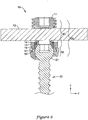
- the upper housing 40 may include a series of plastically deformable tabs 60 circumferentially arranged around a lower end of the upper housing 40.
- Each tab 60 may have a portion that extends radially outward beyond a radial extent of the bore of the housing 30, and may also have a portion that extends radially inside the bore.
- the tabs 60 may be forced radially outward during assembly of the upper housing 40 and the lower housing 50 to couple the upper housing 40 with the lower housing 50.
- the lip 61 Radially adjacent to the tabs 60 is a lip 61 at or near the upper end of the lower housing 50.
- the lip 61 may be circumferentially continuous, or may alternatively be circumferentially discontinuous.
- the lip 61 may be a single edge, the bottom side of which can engage the top side of the tabs 60.
- the lip 61 may be formed as a groove, with both upper and lower edges, so that the tabs 60 may engage between the upper and lower edges of the groove.
- the tabs 60 on the upper housing 40 may be expanded radially outward to engage the tabs 60 into a lip 61 on the lower housing 50, thereby non-removably joining the upper and lower housings 40, 50 together.
- the tabs 60 may be manufactured in the radially unexpanded state (e.g., the tabs 60 may initially be oriented in the radially unexpanded state in an equilibrium state), and subsequently plastically deformed via an applied force into the radially expanded state and maintained in the radially expanded state even upon removal of the applied force.
- the upper and lower housings 40, 50 are placed together so that a lower edge 49 of the upper housing 40 is proximate an upper edge 59 of the lower housing 50. Such a placement ensures that the tabs 60 are radially adjacent to the lip 61.
- the retainer assembly 13 and screw 20 may be absent from the upper housing 40 at this stage.
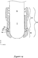
- a mandrel 70 is inserted downward into the bore in the upper housing 40.
- the mandrel 70 may be sized to closely match the bore.
- the mandrel 70 may contact the portions of the tabs 60 that extend into the interior of the bore. Such portions may be notches, as shown in FIG. 13 , or may be other structures, such as inclined surfaces or ramps.
- the tabs 60 may be forced radially outward and plastically deform into a radially outward second configuration. In this particular design, the tabs 60 may bend about their mounted portions, although other suitable plastic deformations may be used to push the tabs 60 into the lip area.
- the tabs 60 remain in their radially expanded state due to the nature of their plastic deformations even in the absence of the applied force.
- the mandrel 70 may then be removed.
- the tabs 60 once radially expanded outwards, may engage the lip 61 on the lower housing 50, and may thereby join the upper housing 40 to the lower housing 50.
- the tabs 60 and lip 61 may be appropriately sized and configured such that once the tabs 60 are plastically deformed into the lip 61 or groove, the tabs 60 may frictionally contact the head 21 of the bone screw 20 subsequently placed in the housing 30 to provide frictional engagement against the head 21. Such frictional contact may restrict pivotal movement between the housing 30 and the bone screw 20.
- the upper housing 40 may freely rotate a full 360 degrees relative to the lower housing 50. However, in some instances it may be desired that the upper housing 40 be freely rotatable relative to the lower housing 50 throughout angles of rotation less than 360 degrees.
- the upper housing 40 may freely rotate relative to the lower housing 50 through an angle of rotation of 270° or less, 250° or less, 225° or less, 210° or less, 200° or less, 190° degrees or less, or 180° degrees or less in some instances. In the event the upper housing 40 were rotated beyond this angle of rotation, the lower housing 50 would begin rotating with the upper housing 40.
- FIGS. 15-25 illustrate three variations of housings which provide limited rotational movement between the upper housing and lower housing through less than 360 degrees.
- FIGS. 15-18 illustrate a first housing 330 of a polyaxial bone anchor having rotational limits between an upper housing 340 and a lower housing 350 of less than 360 degrees. It is noted that the bone screw of the polyaxial bone anchor, extending into the housing 330 through the opening 356 and having a head portion rotationally positioned in the housing 330 has been omitted from the figures. However, it is understood that in use the housing 330 would be polyaxially coupled to a bone engaging portion such as a bone screw 20 similar to the polyaxial bone anchor 10 discussed above.
- the housing 330 includes a lower housing 350 and an upper housing 340.
- the upper housing 340 may include a channel 343, such as a U-shaped channel, defined between opposing arms 341 of the upper housing 340 extending from a first side of the upper housing 340 to a second, opposite side of the upper housing 340.
- the channel 343 may be configured to receive a rod or elongate member inserted into the channel 343 from the top of the housing 330.
- a threaded fastener may be threadably engaged with the threads 342 formed in the opposing arms 341 to secure the elongate member in the channel 343.
- the lower housing 350 may include an opening 356 for receiving a bone screw (not shown) therethrough. Similar to the opening 56, described above, the opening 356 in the lower housing 350 may be generally V-shaped, with angled or converging side walls. Discussion of the opening 56, above, may be applicable to the opening 356. For example, at the "closed" end of the V-shape (i.e., the end in which the side walls are closer together), the angled side walls define a low-angulation direction. Opposite the low-angulation direction, at the "open" end of the V-shape (i.e., the end in which the side walls are further apart), the angled side walls define a high-angulation direction.
- the upper housing 340 may be rotatably coupled to the lower housing 350.
- the upper housing 340 may include a plurality of circumferentially arranged tabs 360 configured to be disposed in an annular groove 361 of the lower housing 350 to couple the upper housing 340 to the lower housing 350.
- the housing 330 may also include complementary structure between the upper housing 340 and the lower housing 350 for limiting rotation between the upper housing 340 and the lower housing 350.
- the upper housing 340 may include a portion which engages a portion of the lower housing 350 once the upper housing 340 has been rotatably oriented to a threshold position relative to the lower housing 350.
- further rotation of the upper housing 340 results in corresponding rotation of the lower housing 350.
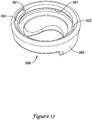
- the upper housing 340 may include a protuberance, shown as a pin 380 configured to travel in a groove 390 formed in the lower housing 350, shown in FIG. 17 .
- the pin 380 may extend downwardly from a lower surface of the upper housing 340.
- the groove 390, shown in FIG. 17 may extend circumferentially around the lower housing 350 less than the full circumference of the lower housing 350.
- the groove 390 which may be open to the upper surface and/or bore of the lower housing 350, may have a first end surface 391 at a first end of the groove 390 and a second end surface 392 at a second end of the groove 390, thus making the groove 390 continuous for less than the full circumference of the lower housing 350.
- the groove 390 may extend through an angle ⁇ (shown in FIG. 18 ) of 270° or less, 250° or less, 225° or less, 210° or less, 200° or less, 190° degrees or less, or 180° degrees or less around the circumference of the lower housing 350.
- the pin 380 When the lower housing 350 is rotatably coupled to the upper housing 340, the pin 380 is positioned in and travels along the groove 390 between the first end surface 391 and the second end surface 392. As shown in FIG. 18 , the pin 380 may travel in the groove 390 through an angle ⁇ , which may be less than the angle ⁇ taking into account the width of the pin 380. In some instances, the angle ⁇ of travel of the pin 380 in the groove 390 may be 270° or less, 250° or less, 225° or less, 210° or less, 200° or less, 190° degrees or less, or 180° degrees or less.
- the housing 330 may be desirable to configure the housing 330 such that the angle ⁇ of travel of the pin 380 in the groove 390 may be at least 180°, to ensure all possible orientations of the channel 343 relative to the high-angulation direction and/or low-angulation direction of the V-shaped opening 356 in the lower housing 350 may be attained.
- the pin 380 may freely travel in the groove 390 between a first position, or first stop point, in which the pin 380 contacts the first end surface 391 to a second position, or second stop point, in which the pin 380 contacts the second end surface 392 without corresponding rotation of the lower housing 350. Further rotation of the upper housing 340 in the same direction once the pin 380 is rotated into contact with either the first end surface 391 or the second end surface 392 results in corresponding rotation of the lower housing 350 with the upper housing 340.
- FIGS. 19-21 illustrate the components of another housing of a polyaxial bone anchor having rotational limits between an upper housing 440 (shown in FIG. 19 ) and a lower housing 450 (shown in FIG. 20 ) of less than 360 degrees.
- the housing formed by the upper housing 440 and lower housing 450 may resemble that shown in FIG. 15 .
- the bone screw of the polyaxial bone anchor extending into the housing through the opening 456 of the lower housing 450 and having a head portion rotationally positioned in the housing has been omitted from the figures.
- the housing formed of the upper housing 440 and lower housing 450 would be polyaxially coupled to a bone engaging portion such as a bone screw 20 similar to the polyaxial bone anchor 10 discussed above.
- the upper housing 440 may include a channel 443, such as a U-shaped channel, defined between opposing arms 441 of the upper housing 440 extending from a first side of the upper housing 440 to a second, opposite side of the upper housing 440.
- the channel 443 may be configured to receive a rod or elongate member inserted into the channel 443 from the top of the housing 430.
- a threaded fastener may be threadably engaged with the threads 442 formed in the opposing arms 441 to secure the elongate member in the channel 443.
- the lower housing 450 may include an opening 456 for receiving a bone screw (not shown) therethrough. Similar to the opening 56, described above, the opening 456 in the lower housing 450 may be generally V-shaped, with angled or converging side walls. Discussion of the opening 56, above, may be applicable to the opening 456. For example, at the "closed" end of the V-shape (i.e., the end in which the side walls are closer together), the angled side walls define a low-angulation direction. Opposite the low-angulation direction, at the "open" end of the V-shape (i.e., the end in which the side walls are further apart), the angled side walls define a high-angulation direction.
- the upper housing 440 may be rotatably coupled to the lower housing 450.
- the upper housing 440 may include a plurality of circumferentially arranged tabs 460 configured to be disposed in an annular groove 461 of the lower housing 450 to couple the upper housing 440 to the lower housing 450.
- the upper housing 440 and lower housing 450 may also include complementary structure between the upper housing 440 and the lower housing 450 for limiting rotation between the upper housing 440 and the lower housing 450.
- the upper housing 440 may include a portion which engages a portion of the lower housing 450 once the upper housing 440 has been rotatably oriented to a threshold position relative to the lower housing 450.
- further rotation of the upper housing 440 results in corresponding rotation of the lower housing 450.
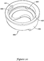
- the upper housing 440 may include a protuberance, shown as a block 380 configured to travel in a groove 490 formed in the lower housing 450, shown in FIG. 20 .
- the block 480 may extend outwardly from a surface of the upper housing 440.
- the block 480 may extend radially outward from a recessed portion 482 of the upper housing 440.
- the groove 490 shown in FIG. 20 , may extend circumferentially around the lower housing 450 less than the full circumference of the lower housing 450.
- the groove 490 which may be open to the upper surface and/or bore of the lower housing 450, may have a first end surface 491 at a first end of the groove 490 and a second end surface 492 at a second end of the groove 490, thus making the groove 490 continuous for less than the full circumference of the lower housing 450.
- the groove 490 may extend through an angle ⁇ (shown in FIG. 21 ) of 270° or less, 250° or less, 225° or less, 210° or less, 200° or less, 190° degrees or less, or 180° degrees or less around the circumference of the lower housing 450.
- the block 480 When the lower housing 450 is rotatably coupled to the upper housing 440, the block 480 is positioned in and travels along the groove 490 between the first end surface 491 and the second end surface 492. As shown in FIG. 21 , the pin 480 may travel in the groove 490 through an angle ⁇ , which may be less than the angle ⁇ taking into account the width of the block 480. In some instances, the angle ⁇ of travel of the block 480 in the groove 490 may be 270° or less, 250° or less, 225° or less, 210° or less, 200° or less, 190° degrees or less, or 180° degrees or less.
- the upper housing 440 and lower housing 450 may be configured such that the angle ⁇ of travel of the block 480 in the groove 490 may be at least 180°, to ensure all possible orientations of the channel 443 relative to the high-angulation direction and/or low-angulation direction of the V-shaped opening 456 in the lower housing 450 may be attained.
- the block 480 may freely travel in the groove 490 between a first position, or first stop point, in which the block 480 contacts the first end surface 491 to a second position, or second stop point, in which the block 480 contacts the second end surface 492 without corresponding rotation of the lower housing 450. Further rotation of the upper housing 440 in the same direction once the block 480 is rotated into contact with either the first end surface 491 or the second end surface 492 results in corresponding rotation of the lower housing 450 with the upper housing 440.
- FIGS. 22-25 illustrate a third housing 530 of a polyaxial bone anchor having rotational limits between an upper housing 540 and a lower housing 550 of less than 360 degrees. It is noted that the bone screw of the polyaxial bone anchor, extending into the housing 530 through the opening 556 and having a head portion rotationally positioned in the housing 530 has been omitted from the figures. However, it is understood that in use the housing 530 would be polyaxially coupled to a bone engaging portion such as a bone screw 20 similar to the polyaxial bone anchor 10 discussed above.
- the housing 530 includes a lower housing 550 and an upper housing 540.
- the upper housing 540 may include a channel 543, such as a U-shaped channel, defined between opposing arms 541 of the upper housing 540 extending from a first side of the upper housing 540 to a second, opposite side of the upper housing 540.
- the channel 543 may be configured to receive a rod or elongate member inserted into the channel 543 from the top of the housing 530.
- a threaded fastener may be threadably engaged with the threads 542 formed in the opposing arms 541 to secure the elongate member in the channel 543.
- the lower housing 550 may include an opening 556 for receiving a bone screw (not shown) therethrough. Similar to the opening 56, described above, the opening 556 in the lower housing 550 may be generally V-shaped, with angled or converging side walls. Discussion of the opening 56, above, may be applicable to the opening 556. For example, at the "closed" end of the V-shape (i.e., the end in which the side walls are closer together), the angled side walls define a low-angulation direction. Opposite the low-angulation direction, at the "open" end of the V-shape (i.e., the end in which the side walls are further apart), the angled side walls define a high-angulation direction.
- the upper housing 540 may be rotatably coupled to the lower housing 550.
- the upper housing 540 may include a plurality of circumferentially arranged tabs 560 configured to be disposed in an annular groove 561 of the lower housing 550 to couple the upper housing 540 to the lower housing 550.
- the housing 530 may also include complementary structure between the upper housing 540 and the lower housing 550 for limiting rotation between the upper housing 540 and the lower housing 550.
- the upper housing 540 may include a portion which engages a portion of the lower housing 550 once the upper housing 540 has been rotatably oriented to a threshold position relative to the lower housing 550. Thus, further rotation of the upper housing 540 results in corresponding rotation of the lower housing 550.
- the lower housing 550 may include a protuberance, shown as a projection 580 configured to travel in a groove 590 formed in the upper housing 540, shown in FIG. 23 .
- the projection 580 may extend upwardly from an upper surface of the lower housing 550.
- the groove 590 shown in FIG. 23 , may extend circumferentially around the upper housing 540 less than the full circumference of the upper housing 540.
- the groove 590 which may be open to the lower surface and/or outer surface of the upper housing 540, may have a first end surface 591 at a first end of the groove 590 and a second end surface 592 (shown in FIG.
- the groove 590 may extend through an angle ⁇ (shown in FIG. 18 ) of 270° or less, 250° or less, 225° or less, 210° or less, 200° or less, 190° degrees or less, or 180° degrees or less around the circumference of the upper housing 540.
- the projection 580 When the lower housing 550 is rotatably coupled to the upper housing 540, the projection 580 is positioned in and travels along the groove 590 between the first end surface 591 and the second end surface 592. As shown in FIG. 25 , the projection 580 may travel in the groove 590 through an angle ⁇ , which may be less than the angle ⁇ taking into account the width of the projection 580. In some instances, the angle ⁇ of travel of the projection 580 in the groove 590 may be 270° or less, 250° or less, 225° or less, 210° or less, 200° or less, 190° degrees or less, or 180° degrees or less.
- the housing 530 may be desirable to configure the housing 530 such that the angle ⁇ of travel of the projection 580 in the groove 590 may be at least 180°, to ensure all possible orientations of the channel 543 relative to the high-angulation direction and/or low-angulation direction of the V-shaped opening 556 in the lower housing 550 may be attained.
- the projection 580 may freely travel in the groove 590 between a first position, or first stop point, in which the projection 580 contacts the first end surface 591 to a second position, or second stop point, in which the projection 580 contacts the second end surface 592 without corresponding rotation of the lower housing 550. Further rotation of the upper housing 540 in the same direction once the projection 580 is rotated into contact with either the first end surface 591 or the second end surface 592 results in corresponding rotation of the lower housing 550 with the upper housing 540.
- housings which provide limited rotational movement between the upper housing and lower housing through less than 360 degrees, including those described above and illustrated in FIGS. 15-25 , will now be described. While such usage will be described with regard to the housing 330, the discussion may be equally applicable to the usage of the other described embodiments.
- the medical personnel may secure the bone screw into a bony structure of a patient by rotating the bone screw with a driver, and thus screwing the bone screw into the bony structure.
- the bone screw may be secured to the bony structure without needing to maintain the housing 330 in any particular rotational orientation.
- the medical personnel may then orient the housing 330 as desired.
- the medical personnel may engage the upper housing 340 with a medical instrument configured to be manipulated in order to rotate the upper housing 340.
- the upper housing 340 may be rotated until the protuberance (e.g., the pin 380) contacts a stop (e.g., one of the first and second end surfaces 391, 392) of the lower housing 350.
- a stop e.g., one of the first and second end surfaces 391, 392
- the upper housing 340 (and thus the lower housing 350) may be further rotated until the high-angulation direction and/or low-angulation direction of the V-shaped opening 356 in the lower housing 350 is positioned in a desired rotational orientation.
- the upper housing 340 (and thus the lower housing 350) may be rotated in a first direction until the high-angulation direction of the V-shaped opening 356 (i.e., the base of the V) is positioned in an orientation in which that the greatest angulation between the housing 330 and the bone screw is desired.
- the high-angulation direction of the V-shaped opening 356 i.e., the base of the V
- the upper housing 340 may be rotated in an opposite, second direction in order to orient the longitudinal axis of the channel 343 in a desired orientation without further rotating the lower housing 350, if the channel 343 is not already oriented as desired.
- the upper housing 340 may be freely rotated relative to the lower housing 350 in the second direction any desired amount up to the point the protuberance (e.g., the pin 380) contacts the other stop (e.g., the other of the first and second end surfaces 391, 392) of the lower housing 350.
- the housing 330 is configured such that the upper housing 340 may be freely rotated relative to the lower housing 350 through at least 180°, all possible orientations of the channel 343 relative to the high-angulation direction of the V-shaped opening 356 in the lower housing 350 may be attained.
- the elongate member may be inserted into the channel 343 and secured therein with a fastener, such as threaded cap screw, which may simultaneously lock the angle of the housing 330 relative to the bone screw.
Landscapes
- Health & Medical Sciences (AREA)
- Orthopedic Medicine & Surgery (AREA)
- Life Sciences & Earth Sciences (AREA)
- Neurology (AREA)
- Surgery (AREA)
- Heart & Thoracic Surgery (AREA)
- Engineering & Computer Science (AREA)
- Biomedical Technology (AREA)
- Nuclear Medicine, Radiotherapy & Molecular Imaging (AREA)
- Medical Informatics (AREA)
- Molecular Biology (AREA)
- Animal Behavior & Ethology (AREA)
- General Health & Medical Sciences (AREA)
- Public Health (AREA)
- Veterinary Medicine (AREA)
- Surgical Instruments (AREA)
Applications Claiming Priority (1)
| Application Number | Priority Date | Filing Date | Title |
|---|---|---|---|
| US13/044,174 US8337530B2 (en) | 2011-03-09 | 2011-03-09 | Polyaxial pedicle screw with increased angulation |
Publications (3)
| Publication Number | Publication Date |
|---|---|
| EP2497435A2 true EP2497435A2 (fr) | 2012-09-12 |
| EP2497435A3 EP2497435A3 (fr) | 2012-10-03 |
| EP2497435B1 EP2497435B1 (fr) | 2014-04-23 |
Family
ID=45887860
Family Applications (1)
| Application Number | Title | Priority Date | Filing Date |
|---|---|---|---|
| EP12001589.6A Active EP2497435B1 (fr) | 2011-03-09 | 2012-03-08 | Vis de pédicule polyaxial à angulation accrue |
Country Status (2)
| Country | Link |
|---|---|
| US (4) | US8337530B2 (fr) |
| EP (1) | EP2497435B1 (fr) |
Cited By (2)
| Publication number | Priority date | Publication date | Assignee | Title |
|---|---|---|---|---|
| US9532810B2 (en) | 2011-03-09 | 2017-01-03 | Zimmer Spine, Inc. | Polyaxial pedicle screw with increased angulation |
| EP3482703A1 (fr) * | 2017-11-10 | 2019-05-15 | Biedermann Technologies GmbH & Co. KG | Ensemble de distraction et de compression, en particulier pour la chirurgie osseuse |
Families Citing this family (99)
| Publication number | Priority date | Publication date | Assignee | Title |
|---|---|---|---|---|
| US7833250B2 (en) | 2004-11-10 | 2010-11-16 | Jackson Roger P | Polyaxial bone screw with helically wound capture connection |
| US7862587B2 (en) | 2004-02-27 | 2011-01-04 | Jackson Roger P | Dynamic stabilization assemblies, tool set and method |
| US8876868B2 (en) | 2002-09-06 | 2014-11-04 | Roger P. Jackson | Helical guide and advancement flange with radially loaded lip |
| US7621918B2 (en) | 2004-11-23 | 2009-11-24 | Jackson Roger P | Spinal fixation tool set and method |
| US7377923B2 (en) | 2003-05-22 | 2008-05-27 | Alphatec Spine, Inc. | Variable angle spinal screw assembly |
| US8936623B2 (en) | 2003-06-18 | 2015-01-20 | Roger P. Jackson | Polyaxial bone screw assembly |
| US7776067B2 (en) | 2005-05-27 | 2010-08-17 | Jackson Roger P | Polyaxial bone screw with shank articulation pressure insert and method |
| US7766915B2 (en) | 2004-02-27 | 2010-08-03 | Jackson Roger P | Dynamic fixation assemblies with inner core and outer coil-like member |
| US7179261B2 (en) | 2003-12-16 | 2007-02-20 | Depuy Spine, Inc. | Percutaneous access devices and bone anchor assemblies |
| US11419642B2 (en) | 2003-12-16 | 2022-08-23 | Medos International Sarl | Percutaneous access devices and bone anchor assemblies |
| US7160300B2 (en) | 2004-02-27 | 2007-01-09 | Jackson Roger P | Orthopedic implant rod reduction tool set and method |
| JP2007525274A (ja) | 2004-02-27 | 2007-09-06 | ロジャー・ピー・ジャクソン | 整形外科インプラントロッド整復器具セット及び方法 |
| US11241261B2 (en) | 2005-09-30 | 2022-02-08 | Roger P Jackson | Apparatus and method for soft spinal stabilization using a tensionable cord and releasable end structure |
| US8926672B2 (en) | 2004-11-10 | 2015-01-06 | Roger P. Jackson | Splay control closure for open bone anchor |
| US8444681B2 (en) | 2009-06-15 | 2013-05-21 | Roger P. Jackson | Polyaxial bone anchor with pop-on shank, friction fit retainer and winged insert |
| US9168069B2 (en) | 2009-06-15 | 2015-10-27 | Roger P. Jackson | Polyaxial bone anchor with pop-on shank and winged insert with lower skirt for engaging a friction fit retainer |
| US9980753B2 (en) | 2009-06-15 | 2018-05-29 | Roger P Jackson | pivotal anchor with snap-in-place insert having rotation blocking extensions |
| WO2006057837A1 (fr) | 2004-11-23 | 2006-06-01 | Jackson Roger P | Structure d'accrochage pour outil de fixation spinale |
| US7955358B2 (en) | 2005-09-19 | 2011-06-07 | Albert Todd J | Bone screw apparatus, system and method |
| US8007522B2 (en) | 2008-02-04 | 2011-08-30 | Depuy Spine, Inc. | Methods for correction of spinal deformities |
| EP2346424B1 (fr) * | 2008-10-09 | 2016-07-27 | Total Connect Spine, Llc | Ensemble de liaison spinale |
| ES2548580T3 (es) | 2009-02-20 | 2015-10-19 | Biedermann Technologies Gmbh & Co. Kg | Parte receptora para alojar una varilla para el acoplamiento a un elemento de anclaje óseo y dispositivo de anclaje óseo que incluye tal parte receptora |
| WO2013043218A1 (fr) | 2009-06-15 | 2013-03-28 | Jackson Roger P | Dispositif d'ancrage osseux polyaxial doté d'une tige à enclenchement par pression et insert à ailettes à pince de compression à ajustement par friction |
| EP2753252A1 (fr) | 2009-06-15 | 2014-07-16 | Jackson, Roger P. | Ancrage osseux polyaxial avec tige fixée par pression et élément de retenue à ajustement serré doté d'un verrou de bordure discret |
| US11229457B2 (en) | 2009-06-15 | 2022-01-25 | Roger P. Jackson | Pivotal bone anchor assembly with insert tool deployment |
| US9044272B2 (en) * | 2009-11-09 | 2015-06-02 | Ebi, Llc | Multiplanar bone anchor system |
| US8641717B2 (en) | 2010-07-01 | 2014-02-04 | DePuy Synthes Products, LLC | Guidewire insertion methods and devices |
| US10603083B1 (en) | 2010-07-09 | 2020-03-31 | Theken Spine, Llc | Apparatus and method for limiting a range of angular positions of a screw |
| US9084634B1 (en) | 2010-07-09 | 2015-07-21 | Theken Spine, Llc | Uniplanar screw |
| JP2013545527A (ja) | 2010-11-02 | 2013-12-26 | ロジャー・ピー・ジャクソン | ポップオン式シャンクと枢動可能な保持部とを有する多軸の骨アンカー |
| EP2462889B1 (fr) * | 2010-12-13 | 2013-08-21 | Biedermann Technologies GmbH & Co. KG | Dispositif d'ancrage d'os |
| US9603630B2 (en) * | 2011-04-29 | 2017-03-28 | Warsaw Orthopedic, Inc. | Rotatable base multi-axial screw assembly |
| US9681894B2 (en) | 2011-07-15 | 2017-06-20 | Globus Medical, Inc. | Orthopedic fixation devices and methods of installation thereof |
| US9999447B2 (en) | 2011-07-15 | 2018-06-19 | Globus Medical, Inc. | Orthopedic fixation devices and methods of installation thereof |
| US9993269B2 (en) * | 2011-07-15 | 2018-06-12 | Globus Medical, Inc. | Orthopedic fixation devices and methods of installation thereof |
| EP2918237A1 (fr) * | 2011-09-15 | 2015-09-16 | Biedermann Technologies GmbH & Co. KG | Dispositif d'ancrage d'os polyaxial doté d'un angle de pivot élargi |
| EP2939623A1 (fr) | 2011-10-27 | 2015-11-04 | Biedermann Technologies GmbH & Co. KG | Dispositif d'ancrage d'os polyaxial à forte inclinaison |
| US8911479B2 (en) | 2012-01-10 | 2014-12-16 | Roger P. Jackson | Multi-start closures for open implants |
| EP2837347B1 (fr) * | 2012-01-30 | 2018-10-03 | Biedermann Technologies GmbH & Co. KG | Dispositif d'ancrage d'os |
| US20140074169A1 (en) * | 2012-09-13 | 2014-03-13 | Warsaw Orthopedic, Inc. | Spinal correction system and method |
| US9782204B2 (en) | 2012-09-28 | 2017-10-10 | Medos International Sarl | Bone anchor assemblies |
| WO2014062694A1 (fr) * | 2012-10-18 | 2014-04-24 | Deroyal Industries, Inc. | Ensemble vis pédiculaire |
| US8911478B2 (en) | 2012-11-21 | 2014-12-16 | Roger P. Jackson | Splay control closure for open bone anchor |
| US20140214084A1 (en) * | 2013-01-28 | 2014-07-31 | Roger P. Jackson | Polyaxial bone anchor with receiver with spheric edge for friction fit |
| US10058354B2 (en) | 2013-01-28 | 2018-08-28 | Roger P. Jackson | Pivotal bone anchor assembly with frictional shank head seating surfaces |
| US8852239B2 (en) | 2013-02-15 | 2014-10-07 | Roger P Jackson | Sagittal angle screw with integral shank and receiver |
| US9724145B2 (en) | 2013-03-14 | 2017-08-08 | Medos International Sarl | Bone anchor assemblies with multiple component bottom loading bone anchors |
| US9775660B2 (en) | 2013-03-14 | 2017-10-03 | DePuy Synthes Products, Inc. | Bottom-loading bone anchor assemblies and methods |
| US20140277159A1 (en) | 2013-03-14 | 2014-09-18 | DePuy Synthes Products, LLC | Bottom-loading bone anchor assemblies |
| US20140277153A1 (en) | 2013-03-14 | 2014-09-18 | DePuy Synthes Products, LLC | Bone Anchor Assemblies and Methods With Improved Locking |
| US9433445B2 (en) | 2013-03-14 | 2016-09-06 | DePuy Synthes Products, Inc. | Bone anchors and surgical instruments with integrated guide tips |
| US9259247B2 (en) | 2013-03-14 | 2016-02-16 | Medos International Sarl | Locking compression members for use with bone anchor assemblies and methods |
| US10342582B2 (en) | 2013-03-14 | 2019-07-09 | DePuy Synthes Products, Inc. | Bone anchor assemblies and methods with improved locking |
| FR3006933B1 (fr) * | 2013-06-13 | 2015-12-04 | Illinois Tool Works | Outil de fixation a tir indirect, organe de propulsion et element de fixation portant cet organe pour l'outil, et procede de pose d'un element de fixation |
| US9566092B2 (en) | 2013-10-29 | 2017-02-14 | Roger P. Jackson | Cervical bone anchor with collet retainer and outer locking sleeve |
| US20150134006A1 (en) * | 2013-11-08 | 2015-05-14 | Blackstone Medical, Inc. | Lockable Pedicle Fastener |
| EP2873383B1 (fr) * | 2013-11-14 | 2016-10-19 | Biedermann Technologies GmbH & Co. KG | Dispositif d'ancrage d'os polyaxial doté d'un angle de pivot élargi |
| US9717533B2 (en) | 2013-12-12 | 2017-08-01 | Roger P. Jackson | Bone anchor closure pivot-splay control flange form guide and advancement structure |
| US9451993B2 (en) | 2014-01-09 | 2016-09-27 | Roger P. Jackson | Bi-radial pop-on cervical bone anchor |
| EP2893889B1 (fr) * | 2014-01-13 | 2016-09-14 | Biedermann Technologies GmbH & Co. KG | Ensemble de couplage d'une tige à un élément d'ancrage osseux et dispositif d'ancrage osseux polyaxial |
| US10918419B2 (en) * | 2014-04-01 | 2021-02-16 | K2M, Inc. | Spinal fixation device |
| US9549765B2 (en) * | 2014-04-03 | 2017-01-24 | Zimmer Spine, Inc. | Uniplanar bone screw |
| US9597119B2 (en) | 2014-06-04 | 2017-03-21 | Roger P. Jackson | Polyaxial bone anchor with polymer sleeve |
| US10064658B2 (en) | 2014-06-04 | 2018-09-04 | Roger P. Jackson | Polyaxial bone anchor with insert guides |
| US10543021B2 (en) | 2014-10-21 | 2020-01-28 | Roger P. Jackson | Pivotal bone anchor assembly having an open ring positioner for a retainer |
| US9924975B2 (en) | 2014-10-21 | 2018-03-27 | Roger P. Jackson | Bone anchor having a snap-fit assembly |
| US20160160906A1 (en) | 2014-12-05 | 2016-06-09 | Black & Decker Inc. | Swivel hanger |
| US10132347B2 (en) * | 2014-12-05 | 2018-11-20 | Black & Decker Inc. | Swivel hanger system |
| US10149702B2 (en) | 2015-01-12 | 2018-12-11 | Imds Llc | Polyaxial screw and rod system |
| US9707013B2 (en) * | 2015-04-30 | 2017-07-18 | Warsaw Orthopedic, Inc. | Spinal implant system and methods of use |
| US10034691B1 (en) | 2015-12-03 | 2018-07-31 | Nuvasive, Inc. | Bone anchor |
| EP3973898B1 (fr) | 2016-02-26 | 2025-06-04 | Medos International Sarl | Élément de fixation d'os polyaxial |
| EP4278998B1 (fr) | 2016-07-29 | 2025-05-21 | Zimmer Biomet Spine, Inc. | Limiteur de logement d'ancrage osseux |
| EP4008280A1 (fr) | 2016-08-22 | 2022-06-08 | Zimmer Biomet Spine, Inc. | Dérotateurs articulés pour systèmes vertébraux de déformation |
| US20190262044A1 (en) | 2016-09-16 | 2019-08-29 | Noah Roth | Bone anchor, instruments, and methods for use |
| US9763700B1 (en) * | 2016-12-14 | 2017-09-19 | Spine Wave, Inc. | Polyaxial bone screw |
| US11419639B2 (en) | 2017-03-30 | 2022-08-23 | K2M, Inc. | Modular offset screw |
| WO2018183314A1 (fr) | 2017-03-30 | 2018-10-04 | K2M, Inc. | Appareil d'ancrage osseux et procédé d'utilisation de celui-ci |
| US11298156B2 (en) | 2017-03-30 | 2022-04-12 | K2M, Inc. | Modular screw |
| US11026730B2 (en) | 2017-05-10 | 2021-06-08 | Medos International Sarl | Bone anchors with drag features and related methods |
| US10610265B1 (en) * | 2017-07-31 | 2020-04-07 | K2M, Inc. | Polyaxial bone screw with increased angulation |
| US10507043B1 (en) | 2017-10-11 | 2019-12-17 | Seaspine Orthopedics Corporation | Collet for a polyaxial screw assembly |
| US10285738B1 (en) * | 2017-12-12 | 2019-05-14 | Spinal Llc | Polyaxial ball and socket fastener with spot welded blocking ring |
| US11123198B2 (en) | 2018-11-13 | 2021-09-21 | Degen Medical, Inc. | Expandable spacers |
| US11559333B2 (en) * | 2019-01-21 | 2023-01-24 | Zimmer Biomet Spine, Inc. | Bone anchor |
| US11234829B2 (en) | 2019-01-21 | 2022-02-01 | Degen Medical, Inc. | Expandable intervertebral spacers |
| WO2020176695A2 (fr) * | 2019-02-27 | 2020-09-03 | Lenkbar Llc | Ensemble de fixation vertébrale |
| US11547575B2 (en) | 2019-09-27 | 2023-01-10 | Degen Medical, Inc. | Expandable intervertebral spacers |
| US12262921B2 (en) | 2020-06-26 | 2025-04-01 | K2M, Inc. | Modular head assembly |
| WO2022108875A1 (fr) | 2020-11-19 | 2022-05-27 | K2M, Inc. | Ensemble tête modulaire pour fixation rachidienne |
| CN112370138A (zh) * | 2020-11-24 | 2021-02-19 | 朱晓东 | 儿童脊柱侧弯矫形螺钉及系统 |
| AU2022230734A1 (en) | 2021-03-05 | 2023-10-19 | Medos International Sarl | Multi-feature polyaxial screw |
| US12127766B2 (en) | 2021-03-05 | 2024-10-29 | Medos International Sàrl | Selectively locking polyaxial screw |
| US11369417B1 (en) | 2021-06-08 | 2022-06-28 | Curiteva, Inc. | Modular polyaxial pedicle screw assembly with split ring |
| EP4129220B1 (fr) * | 2021-08-04 | 2024-07-03 | Biedermann Technologies GmbH & Co. KG | Dispositif de couplage d'une tige à un élément d'ancrage d'os et son procédé de fabrication |
| CN114343815B (zh) * | 2022-03-17 | 2022-06-03 | 长沙市第三医院 | 一种多平面皮质骨螺钉、骨骼定位装置及定位使用方法 |
| KR102790118B1 (ko) | 2022-11-23 | 2025-04-07 | (주)씨티엘바이오테크 | 방향을 선택하여 추가적으로 편향되는 각도를 갖는 다축 척추 스크류 |
| US12343055B1 (en) | 2024-08-02 | 2025-07-01 | Institute For Spine & Scoliosis, P.A. | Anchor device for bone implantation during surgical procedures |
| DE102024124421A1 (de) * | 2024-08-27 | 2026-03-05 | Aesculap Ag | Medizinische Schraube und medizinische Schraubenvorrichtung |
Family Cites Families (86)
| Publication number | Priority date | Publication date | Assignee | Title |
|---|---|---|---|---|
| US200600A (en) | 1878-02-26 | Improvement in fire-escapes | ||
| US20070179096A1 (en) | 1996-04-24 | 2007-08-02 | Novo Nordisk A/S | Pharmaceutical Formulation |
| DE29710484U1 (de) | 1997-06-16 | 1998-10-15 | Howmedica GmbH, 24232 Schönkirchen | Aufnahmeteil für ein Haltebauteil eines Wirbelsäulenimplantats |
| FR2794637B1 (fr) | 1999-06-14 | 2001-12-28 | Scient X | Implant pour dispositif d'osteosynthese notamment du rachis |
| US6755829B1 (en) * | 2000-09-22 | 2004-06-29 | Depuy Acromed, Inc. | Lock cap anchor assembly for orthopaedic fixation |
| DE10055888C1 (de) | 2000-11-10 | 2002-04-25 | Biedermann Motech Gmbh | Knochenschraube |
| US7862587B2 (en) * | 2004-02-27 | 2011-01-04 | Jackson Roger P | Dynamic stabilization assemblies, tool set and method |
| US6579292B2 (en) * | 2001-06-18 | 2003-06-17 | Sdgi Holdings, Inc. | Connection assembly for spinal implant systems |
| FR2826861B1 (fr) * | 2001-07-04 | 2004-06-18 | Materiel Orthopedique En Abreg | Connecteur lateral a decalage ajustable pour dispositif de correction et de stabilisation du rachis, organe de fixation adapte a ce connecteur et ensemble forme par ce connecteur et cet organe de fixation |
| US6520963B1 (en) | 2001-08-13 | 2003-02-18 | Mckinley Lawrence M. | Vertebral alignment and fixation assembly |
| US6974460B2 (en) | 2001-09-14 | 2005-12-13 | Stryker Spine | Biased angulation bone fixation assembly |
| US7201754B2 (en) * | 2002-02-08 | 2007-04-10 | Kenneth Stewart | Device for installing an anchor in a bone |
| US20030171755A1 (en) | 2002-03-05 | 2003-09-11 | Moseley Colin F. | Bone screws |
| US8162989B2 (en) * | 2002-11-04 | 2012-04-24 | Altus Partners, Llc | Orthopedic rod system |
| US7141051B2 (en) * | 2003-02-05 | 2006-11-28 | Pioneer Laboratories, Inc. | Low profile spinal fixation system |
| US7621918B2 (en) * | 2004-11-23 | 2009-11-24 | Jackson Roger P | Spinal fixation tool set and method |
| US7377923B2 (en) | 2003-05-22 | 2008-05-27 | Alphatec Spine, Inc. | Variable angle spinal screw assembly |
| US8936623B2 (en) * | 2003-06-18 | 2015-01-20 | Roger P. Jackson | Polyaxial bone screw assembly |
| US6981973B2 (en) | 2003-08-11 | 2006-01-03 | Mckinley Laurence M | Low profile vertebral alignment and fixation assembly |
| AU2004266737B2 (en) | 2003-08-20 | 2010-05-13 | Warsaw Orthopedic, Inc. | Multi-axial orthopedic device and system, e.g. for spinal surgery |
| US7588575B2 (en) * | 2003-10-21 | 2009-09-15 | Innovative Spinal Technologies | Extension for use with stabilization systems for internal structures |
| US8926700B2 (en) * | 2003-12-10 | 2015-01-06 | Gmedelware 2 LLC | Spinal facet joint implant |
| EP1699370A4 (fr) | 2003-12-30 | 2008-08-06 | Depuy Spine Sarl | Ensembles d'ancrage osseux et leurs procedes de fabrication |
| US20050154391A1 (en) | 2003-12-30 | 2005-07-14 | Thomas Doherty | Bone anchor assemblies |
| US7678137B2 (en) | 2004-01-13 | 2010-03-16 | Life Spine, Inc. | Pedicle screw constructs for spine fixation systems |
| US7503924B2 (en) * | 2004-04-08 | 2009-03-17 | Globus Medical, Inc. | Polyaxial screw |
| US20050228382A1 (en) * | 2004-04-12 | 2005-10-13 | Marc Richelsoph | Screw and rod fixation assembly and device |
| US7264621B2 (en) | 2004-06-17 | 2007-09-04 | Sdgi Holdings, Inc. | Multi-axial bone attachment assembly |
| US7766945B2 (en) * | 2004-08-10 | 2010-08-03 | Lanx, Inc. | Screw and rod fixation system |
| US7572280B2 (en) * | 2004-10-05 | 2009-08-11 | Warsaw Orthopedic, Inc. | Multi-axial anchor assemblies for spinal implants and methods |
| US20100331883A1 (en) * | 2004-10-15 | 2010-12-30 | Schmitz Gregory P | Access and tissue modification systems and methods |
| US7935134B2 (en) * | 2004-10-20 | 2011-05-03 | Exactech, Inc. | Systems and methods for stabilization of bone structures |
| US20110190822A1 (en) * | 2004-11-16 | 2011-08-04 | James Spitler | Internal Structure Stabilization System for Spanning Three or More Structures |
| US7875065B2 (en) * | 2004-11-23 | 2011-01-25 | Jackson Roger P | Polyaxial bone screw with multi-part shank retainer and pressure insert |
| US7445627B2 (en) * | 2005-01-31 | 2008-11-04 | Alpinespine, Llc | Polyaxial pedicle screw assembly |
| WO2006096351A1 (fr) | 2005-03-03 | 2006-09-14 | Accelerated Innovation, Llc | Stabilisation vertebrale au moyen d'un element d'ancrage osseux et d'un siege d'element d'ancrage avec element de blocage tangentiel |
| WO2006116437A2 (fr) * | 2005-04-25 | 2006-11-02 | Synthes (U.S.A.) | Ancrage osseux equipe d'un bouchon de verrouillage et procede de fixation vertebrale |
| US20090093844A1 (en) * | 2005-09-30 | 2009-04-09 | Jackson Roger P | Elastic covered dynamic stabilization connector and assembly |
| US7927359B2 (en) * | 2005-10-06 | 2011-04-19 | Paradigm Spine, Llc | Polyaxial screw |
| US8100946B2 (en) * | 2005-11-21 | 2012-01-24 | Synthes Usa, Llc | Polyaxial bone anchors with increased angulation |
| US8518084B2 (en) * | 2006-01-24 | 2013-08-27 | Biedermann Technologies Gmbh & Co. Kg | Connecting rod with external flexible element |
| WO2008022268A2 (fr) * | 2006-08-16 | 2008-02-21 | Pioneer Surgical Technology, Inc. | dispositif d'ancrage de tige spinale et procédé |
| EP2081507A1 (fr) * | 2006-09-25 | 2009-07-29 | Zimmer Spine, Inc. | Appareil de liaison d'un élément longitudinal à une partie d'os |
| US8016862B2 (en) * | 2006-09-27 | 2011-09-13 | Innovasis, Inc. | Spinal stabilizing system |
| US8167910B2 (en) * | 2006-10-16 | 2012-05-01 | Innovative Delta Technology Llc | Bone screw and associated assembly and methods of use thereof |
| US8066744B2 (en) * | 2006-11-10 | 2011-11-29 | Warsaw Orthopedic, Inc. | Keyed crown orientation for multi-axial screws |
| US8409256B2 (en) * | 2006-12-28 | 2013-04-02 | Depuy Spine, Inc. | Spinal anchoring screw |
| US9962194B2 (en) * | 2007-01-15 | 2018-05-08 | Innovative Delta Technology, Llc | Polyaxial spinal stabilizer connector and methods of use thereof |
| US7947065B2 (en) * | 2008-11-14 | 2011-05-24 | Ortho Innovations, Llc | Locking polyaxial ball and socket fastener |
| US7942909B2 (en) * | 2009-08-13 | 2011-05-17 | Ortho Innovations, Llc | Thread-thru polyaxial pedicle screw system |
| US8197518B2 (en) * | 2007-05-16 | 2012-06-12 | Ortho Innovations, Llc | Thread-thru polyaxial pedicle screw system |
| US7951173B2 (en) * | 2007-05-16 | 2011-05-31 | Ortho Innovations, Llc | Pedicle screw implant system |
| US8221471B2 (en) * | 2007-05-24 | 2012-07-17 | Aesculap Implant Systems, Llc | Pedicle screw fixation system |
| US8048121B2 (en) * | 2007-06-05 | 2011-11-01 | Spartek Medical, Inc. | Spine implant with a defelction rod system anchored to a bone anchor and method |
| US7942900B2 (en) * | 2007-06-05 | 2011-05-17 | Spartek Medical, Inc. | Shaped horizontal rod for dynamic stabilization and motion preservation spinal implantation system and method |
| US20090105756A1 (en) * | 2007-10-23 | 2009-04-23 | Marc Richelsoph | Spinal implant |
| US8029539B2 (en) | 2007-12-19 | 2011-10-04 | X-Spine Systems, Inc. | Offset multiaxial or polyaxial screw, system and assembly |
| US8998958B2 (en) * | 2007-12-20 | 2015-04-07 | Aesculap Implant Systems, Llc | Locking device introducer instrument |
| US8007522B2 (en) * | 2008-02-04 | 2011-08-30 | Depuy Spine, Inc. | Methods for correction of spinal deformities |
| US8197515B2 (en) * | 2008-02-18 | 2012-06-12 | Expanding Orthopedics Inc. | Cross-connector assembly |
| US8016861B2 (en) * | 2008-02-26 | 2011-09-13 | Spartek Medical, Inc. | Versatile polyaxial connector assembly and method for dynamic stabilization of the spine |
| US20100030224A1 (en) * | 2008-02-26 | 2010-02-04 | Spartek Medical, Inc. | Surgical tool and method for connecting a dynamic bone anchor and dynamic vertical rod |
| US9603629B2 (en) * | 2008-09-09 | 2017-03-28 | Intelligent Implant Systems Llc | Polyaxial screw assembly |
| CA2739431C (fr) * | 2008-10-01 | 2016-12-06 | Sherwin Hua | Systeme et procede de stabilisation de vertebres spinales par vis pediculaires guidees par fils |
| US8506601B2 (en) | 2008-10-14 | 2013-08-13 | Pioneer Surgical Technology, Inc. | Low profile dual locking fixation system and offset anchor member |
| EP3117788B1 (fr) | 2008-11-03 | 2020-04-01 | Synthes GmbH | Ensemble fixation osseuse plane |
| US8075603B2 (en) * | 2008-11-14 | 2011-12-13 | Ortho Innovations, Llc | Locking polyaxial ball and socket fastener |
| JO3672B1 (ar) | 2008-12-15 | 2020-08-27 | Regeneron Pharma | أجسام مضادة بشرية عالية التفاعل الكيماوي بالنسبة لإنزيم سبتيليسين كنفرتيز بروبروتين / كيكسين نوع 9 (pcsk9). |
| US8821555B2 (en) * | 2009-02-11 | 2014-09-02 | Howmedica Osteonics Corp. | Intervertebral implant with integrated fixation |
| US8636778B2 (en) | 2009-02-11 | 2014-01-28 | Pioneer Surgical Technology, Inc. | Wide angulation coupling members for bone fixation system |
| US9408715B2 (en) * | 2009-04-15 | 2016-08-09 | DePuy Synthes Products, Inc. | Arcuate fixation member |
| US8236035B1 (en) * | 2009-06-16 | 2012-08-07 | Bedor Bernard M | Spinal fixation system and method |
| US9044272B2 (en) * | 2009-11-09 | 2015-06-02 | Ebi, Llc | Multiplanar bone anchor system |
| US8518085B2 (en) * | 2010-06-10 | 2013-08-27 | Spartek Medical, Inc. | Adaptive spinal rod and methods for stabilization of the spine |
| US9084634B1 (en) * | 2010-07-09 | 2015-07-21 | Theken Spine, Llc | Uniplanar screw |
| US9393049B2 (en) * | 2010-08-20 | 2016-07-19 | K2M, Inc. | Spinal fixation system |
| US8337530B2 (en) | 2011-03-09 | 2012-12-25 | Zimmer Spine, Inc. | Polyaxial pedicle screw with increased angulation |
| US8940023B2 (en) * | 2011-08-31 | 2015-01-27 | DePuy Synthes Products, LLC | System and method for cervical midline fixation |
| EP2939623A1 (fr) * | 2011-10-27 | 2015-11-04 | Biedermann Technologies GmbH & Co. KG | Dispositif d'ancrage d'os polyaxial à forte inclinaison |
| EP2606841B1 (fr) * | 2011-12-23 | 2016-03-09 | Biedermann Technologies GmbH & Co. KG | Dispositif polyaxial d'ancrage osseux |
| EP2689734B1 (fr) * | 2012-07-27 | 2016-09-14 | Biedermann Technologies GmbH & Co. KG | Dispositif d'ancrage d'os polyaxial doté d'un angle de pivot élargi |
| US8764804B2 (en) * | 2012-09-28 | 2014-07-01 | Warsaw Orthopedic, Inc. | Bone fastener and methods of use |
| US8911478B2 (en) * | 2012-11-21 | 2014-12-16 | Roger P. Jackson | Splay control closure for open bone anchor |
| US20140188171A1 (en) * | 2012-12-27 | 2014-07-03 | Meng Feng Huang | Bone fixing device |
| US20140214084A1 (en) * | 2013-01-28 | 2014-07-31 | Roger P. Jackson | Polyaxial bone anchor with receiver with spheric edge for friction fit |
| US8852239B2 (en) * | 2013-02-15 | 2014-10-07 | Roger P Jackson | Sagittal angle screw with integral shank and receiver |
-
2011
- 2011-03-09 US US13/044,174 patent/US8337530B2/en active Active
-
2012
- 2012-03-08 EP EP12001589.6A patent/EP2497435B1/fr active Active
- 2012-09-14 US US13/616,854 patent/US8685064B2/en active Active
-
2014
- 2014-01-27 US US14/164,797 patent/US9289244B2/en active Active
-
2016
- 2016-02-11 US US15/041,732 patent/US9532810B2/en active Active
Non-Patent Citations (1)
| Title |
|---|
| None |
Cited By (2)
| Publication number | Priority date | Publication date | Assignee | Title |
|---|---|---|---|---|
| US9532810B2 (en) | 2011-03-09 | 2017-01-03 | Zimmer Spine, Inc. | Polyaxial pedicle screw with increased angulation |
| EP3482703A1 (fr) * | 2017-11-10 | 2019-05-15 | Biedermann Technologies GmbH & Co. KG | Ensemble de distraction et de compression, en particulier pour la chirurgie osseuse |
Also Published As
| Publication number | Publication date |
|---|---|
| US9532810B2 (en) | 2017-01-03 |
| US8685064B2 (en) | 2014-04-01 |
| US20120232598A1 (en) | 2012-09-13 |
| US8337530B2 (en) | 2012-12-25 |
| EP2497435B1 (fr) | 2014-04-23 |
| US20160157895A1 (en) | 2016-06-09 |
| US20140142640A1 (en) | 2014-05-22 |
| EP2497435A3 (fr) | 2012-10-03 |
| US9289244B2 (en) | 2016-03-22 |
| US20130013004A1 (en) | 2013-01-10 |
Similar Documents
| Publication | Publication Date | Title |
|---|---|---|
| US9532810B2 (en) | Polyaxial pedicle screw with increased angulation | |
| US20250049479A1 (en) | Uniplanar bone screw | |
| US12232777B2 (en) | Dynamic support system | |
| US10925646B2 (en) | Polyaxial pedicle screw | |
| JP6486277B2 (ja) | 整形外科用固定装置 | |
| US11076887B2 (en) | Orthopedic fixation devices and methods of installation thereof | |
| US20190247094A1 (en) | Orthopedic fixation devices and methods of installation thereof | |
| US10016223B2 (en) | Orthopedic fixation devices and methods of installation thereof | |
| US12245795B2 (en) | Orthopedic fixation devices and methods of installation thereof | |
| US9498254B2 (en) | Bottom-loading bone anchor assemblies | |
| US9326796B2 (en) | Uni-planer bone fixation assembly | |
| US20060200128A1 (en) | Bone anchor | |
| US20140188175A1 (en) | Orthopedic Fixation Devices and Methods of Installation Thereof | |
| JP2007516808A (ja) | 骨アンカーアセンブリ | |
| JP2007516811A (ja) | 骨アンカーアセンブリ、および、骨アンカーアセンブリの製造方法 | |
| US20250090203A1 (en) | Orthopedic Fixation Devices and Methods of Installation Thereof | |
| EP3569169B1 (fr) | Dispositifs de fixation orthopédiques |
Legal Events
| Date | Code | Title | Description |
|---|---|---|---|
| PUAL | Search report despatched |
Free format text: ORIGINAL CODE: 0009013 |
|
| PUAI | Public reference made under article 153(3) epc to a published international application that has entered the european phase |
Free format text: ORIGINAL CODE: 0009012 |
|
| AK | Designated contracting states |
Kind code of ref document: A2 Designated state(s): AL AT BE BG CH CY CZ DE DK EE ES FI FR GB GR HR HU IE IS IT LI LT LU LV MC MK MT NL NO PL PT RO RS SE SI SK SM TR |
|
| AX | Request for extension of the european patent |
Extension state: BA ME |
|
| AK | Designated contracting states |
Kind code of ref document: A3 Designated state(s): AL AT BE BG CH CY CZ DE DK EE ES FI FR GB GR HR HU IE IS IT LI LT LU LV MC MK MT NL NO PL PT RO RS SE SI SK SM TR |
|
| AX | Request for extension of the european patent |
Extension state: BA ME |
|
| RIC1 | Information provided on ipc code assigned before grant |
Ipc: A61B 17/70 20060101AFI20120827BHEP |
|
| 17P | Request for examination filed |
Effective date: 20130403 |
|
| GRAP | Despatch of communication of intention to grant a patent |
Free format text: ORIGINAL CODE: EPIDOSNIGR1 |
|
| INTG | Intention to grant announced |
Effective date: 20131008 |
|
| GRAS | Grant fee paid |
Free format text: ORIGINAL CODE: EPIDOSNIGR3 |
|
| RIN1 | Information on inventor provided before grant (corrected) |
Inventor name: HOCH, DEBORAH L. Inventor name: DANT, JACK A. Inventor name: JERKE, ERIC P. Inventor name: HESTAD, HUGH D. Inventor name: LUNDEQUAM, ERIC J. |
|
| GRAA | (expected) grant |
Free format text: ORIGINAL CODE: 0009210 |
|
| AK | Designated contracting states |
Kind code of ref document: B1 Designated state(s): AL AT BE BG CH CY CZ DE DK EE ES FI FR GB GR HR HU IE IS IT LI LT LU LV MC MK MT NL NO PL PT RO RS SE SI SK SM TR |
|
| REG | Reference to a national code |
Ref country code: GB Ref legal event code: FG4D |
|
| REG | Reference to a national code |
Ref country code: CH Ref legal event code: EP |
|
| REG | Reference to a national code |
Ref country code: AT Ref legal event code: REF Ref document number: 663286 Country of ref document: AT Kind code of ref document: T Effective date: 20140515 |
|
| REG | Reference to a national code |
Ref country code: IE Ref legal event code: FG4D |
|
| REG | Reference to a national code |
Ref country code: DE Ref legal event code: R096 Ref document number: 602012001438 Country of ref document: DE Effective date: 20140605 |
|
| REG | Reference to a national code |
Ref country code: AT Ref legal event code: MK05 Ref document number: 663286 Country of ref document: AT Kind code of ref document: T Effective date: 20140423 |
|
| REG | Reference to a national code |
Ref country code: NL Ref legal event code: VDEP Effective date: 20140423 |
|
| REG | Reference to a national code |
Ref country code: LT Ref legal event code: MG4D |
|
| PG25 | Lapsed in a contracting state [announced via postgrant information from national office to epo] |
Ref country code: GR Free format text: LAPSE BECAUSE OF FAILURE TO SUBMIT A TRANSLATION OF THE DESCRIPTION OR TO PAY THE FEE WITHIN THE PRESCRIBED TIME-LIMIT Effective date: 20140724 Ref country code: BG Free format text: LAPSE BECAUSE OF FAILURE TO SUBMIT A TRANSLATION OF THE DESCRIPTION OR TO PAY THE FEE WITHIN THE PRESCRIBED TIME-LIMIT Effective date: 20140723 Ref country code: NL Free format text: LAPSE BECAUSE OF FAILURE TO SUBMIT A TRANSLATION OF THE DESCRIPTION OR TO PAY THE FEE WITHIN THE PRESCRIBED TIME-LIMIT Effective date: 20140423 Ref country code: LT Free format text: LAPSE BECAUSE OF FAILURE TO SUBMIT A TRANSLATION OF THE DESCRIPTION OR TO PAY THE FEE WITHIN THE PRESCRIBED TIME-LIMIT Effective date: 20140423 Ref country code: FI Free format text: LAPSE BECAUSE OF FAILURE TO SUBMIT A TRANSLATION OF THE DESCRIPTION OR TO PAY THE FEE WITHIN THE PRESCRIBED TIME-LIMIT Effective date: 20140423 Ref country code: IS Free format text: LAPSE BECAUSE OF FAILURE TO SUBMIT A TRANSLATION OF THE DESCRIPTION OR TO PAY THE FEE WITHIN THE PRESCRIBED TIME-LIMIT Effective date: 20140823 Ref country code: NO Free format text: LAPSE BECAUSE OF FAILURE TO SUBMIT A TRANSLATION OF THE DESCRIPTION OR TO PAY THE FEE WITHIN THE PRESCRIBED TIME-LIMIT Effective date: 20140723 Ref country code: CY Free format text: LAPSE BECAUSE OF FAILURE TO SUBMIT A TRANSLATION OF THE DESCRIPTION OR TO PAY THE FEE WITHIN THE PRESCRIBED TIME-LIMIT Effective date: 20140423 |
|
| PG25 | Lapsed in a contracting state [announced via postgrant information from national office to epo] |
Ref country code: SE Free format text: LAPSE BECAUSE OF FAILURE TO SUBMIT A TRANSLATION OF THE DESCRIPTION OR TO PAY THE FEE WITHIN THE PRESCRIBED TIME-LIMIT Effective date: 20140423 Ref country code: ES Free format text: LAPSE BECAUSE OF FAILURE TO SUBMIT A TRANSLATION OF THE DESCRIPTION OR TO PAY THE FEE WITHIN THE PRESCRIBED TIME-LIMIT Effective date: 20140423 Ref country code: AT Free format text: LAPSE BECAUSE OF FAILURE TO SUBMIT A TRANSLATION OF THE DESCRIPTION OR TO PAY THE FEE WITHIN THE PRESCRIBED TIME-LIMIT Effective date: 20140423 Ref country code: HR Free format text: LAPSE BECAUSE OF FAILURE TO SUBMIT A TRANSLATION OF THE DESCRIPTION OR TO PAY THE FEE WITHIN THE PRESCRIBED TIME-LIMIT Effective date: 20140423 Ref country code: RS Free format text: LAPSE BECAUSE OF FAILURE TO SUBMIT A TRANSLATION OF THE DESCRIPTION OR TO PAY THE FEE WITHIN THE PRESCRIBED TIME-LIMIT Effective date: 20140423 Ref country code: LV Free format text: LAPSE BECAUSE OF FAILURE TO SUBMIT A TRANSLATION OF THE DESCRIPTION OR TO PAY THE FEE WITHIN THE PRESCRIBED TIME-LIMIT Effective date: 20140423 Ref country code: PL Free format text: LAPSE BECAUSE OF FAILURE TO SUBMIT A TRANSLATION OF THE DESCRIPTION OR TO PAY THE FEE WITHIN THE PRESCRIBED TIME-LIMIT Effective date: 20140423 |
|
| PG25 | Lapsed in a contracting state [announced via postgrant information from national office to epo] |
Ref country code: PT Free format text: LAPSE BECAUSE OF FAILURE TO SUBMIT A TRANSLATION OF THE DESCRIPTION OR TO PAY THE FEE WITHIN THE PRESCRIBED TIME-LIMIT Effective date: 20140825 |
|
| REG | Reference to a national code |
Ref country code: DE Ref legal event code: R097 Ref document number: 602012001438 Country of ref document: DE |
|
| PG25 | Lapsed in a contracting state [announced via postgrant information from national office to epo] |
Ref country code: EE Free format text: LAPSE BECAUSE OF FAILURE TO SUBMIT A TRANSLATION OF THE DESCRIPTION OR TO PAY THE FEE WITHIN THE PRESCRIBED TIME-LIMIT Effective date: 20140423 Ref country code: SK Free format text: LAPSE BECAUSE OF FAILURE TO SUBMIT A TRANSLATION OF THE DESCRIPTION OR TO PAY THE FEE WITHIN THE PRESCRIBED TIME-LIMIT Effective date: 20140423 Ref country code: DK Free format text: LAPSE BECAUSE OF FAILURE TO SUBMIT A TRANSLATION OF THE DESCRIPTION OR TO PAY THE FEE WITHIN THE PRESCRIBED TIME-LIMIT Effective date: 20140423 Ref country code: CZ Free format text: LAPSE BECAUSE OF FAILURE TO SUBMIT A TRANSLATION OF THE DESCRIPTION OR TO PAY THE FEE WITHIN THE PRESCRIBED TIME-LIMIT Effective date: 20140423 Ref country code: RO Free format text: LAPSE BECAUSE OF FAILURE TO SUBMIT A TRANSLATION OF THE DESCRIPTION OR TO PAY THE FEE WITHIN THE PRESCRIBED TIME-LIMIT Effective date: 20140423 Ref country code: BE Free format text: LAPSE BECAUSE OF FAILURE TO SUBMIT A TRANSLATION OF THE DESCRIPTION OR TO PAY THE FEE WITHIN THE PRESCRIBED TIME-LIMIT Effective date: 20140423 |
|
| PLBE | No opposition filed within time limit |
Free format text: ORIGINAL CODE: 0009261 |
|
| STAA | Information on the status of an ep patent application or granted ep patent |
Free format text: STATUS: NO OPPOSITION FILED WITHIN TIME LIMIT |
|
| PG25 | Lapsed in a contracting state [announced via postgrant information from national office to epo] |
Ref country code: IT Free format text: LAPSE BECAUSE OF FAILURE TO SUBMIT A TRANSLATION OF THE DESCRIPTION OR TO PAY THE FEE WITHIN THE PRESCRIBED TIME-LIMIT Effective date: 20140423 |
|
| 26N | No opposition filed |
Effective date: 20150126 |
|
| REG | Reference to a national code |
Ref country code: DE Ref legal event code: R097 Ref document number: 602012001438 Country of ref document: DE Effective date: 20150126 |
|
| PG25 | Lapsed in a contracting state [announced via postgrant information from national office to epo] |
Ref country code: SI Free format text: LAPSE BECAUSE OF FAILURE TO SUBMIT A TRANSLATION OF THE DESCRIPTION OR TO PAY THE FEE WITHIN THE PRESCRIBED TIME-LIMIT Effective date: 20140423 |
|
| PG25 | Lapsed in a contracting state [announced via postgrant information from national office to epo] |
Ref country code: MC Free format text: LAPSE BECAUSE OF FAILURE TO SUBMIT A TRANSLATION OF THE DESCRIPTION OR TO PAY THE FEE WITHIN THE PRESCRIBED TIME-LIMIT Effective date: 20140423 Ref country code: LU Free format text: LAPSE BECAUSE OF FAILURE TO SUBMIT A TRANSLATION OF THE DESCRIPTION OR TO PAY THE FEE WITHIN THE PRESCRIBED TIME-LIMIT Effective date: 20150308 |
|
| REG | Reference to a national code |
Ref country code: CH Ref legal event code: PL |
|
| REG | Reference to a national code |
Ref country code: IE Ref legal event code: MM4A |
|
| PG25 | Lapsed in a contracting state [announced via postgrant information from national office to epo] |
Ref country code: CH Free format text: LAPSE BECAUSE OF NON-PAYMENT OF DUE FEES Effective date: 20150331 Ref country code: IE Free format text: LAPSE BECAUSE OF NON-PAYMENT OF DUE FEES Effective date: 20150308 Ref country code: LI Free format text: LAPSE BECAUSE OF NON-PAYMENT OF DUE FEES Effective date: 20150331 |
|
| REG | Reference to a national code |
Ref country code: FR Ref legal event code: PLFP Year of fee payment: 5 |
|
| PG25 | Lapsed in a contracting state [announced via postgrant information from national office to epo] |
Ref country code: MT Free format text: LAPSE BECAUSE OF FAILURE TO SUBMIT A TRANSLATION OF THE DESCRIPTION OR TO PAY THE FEE WITHIN THE PRESCRIBED TIME-LIMIT Effective date: 20140423 |
|
| REG | Reference to a national code |
Ref country code: FR Ref legal event code: PLFP Year of fee payment: 6 |
|
| PG25 | Lapsed in a contracting state [announced via postgrant information from national office to epo] |
Ref country code: SM Free format text: LAPSE BECAUSE OF FAILURE TO SUBMIT A TRANSLATION OF THE DESCRIPTION OR TO PAY THE FEE WITHIN THE PRESCRIBED TIME-LIMIT Effective date: 20140423 Ref country code: HU Free format text: LAPSE BECAUSE OF FAILURE TO SUBMIT A TRANSLATION OF THE DESCRIPTION OR TO PAY THE FEE WITHIN THE PRESCRIBED TIME-LIMIT; INVALID AB INITIO Effective date: 20120308 |
|
| PG25 | Lapsed in a contracting state [announced via postgrant information from national office to epo] |
Ref country code: TR Free format text: LAPSE BECAUSE OF FAILURE TO SUBMIT A TRANSLATION OF THE DESCRIPTION OR TO PAY THE FEE WITHIN THE PRESCRIBED TIME-LIMIT Effective date: 20140423 |
|
| REG | Reference to a national code |
Ref country code: FR Ref legal event code: PLFP Year of fee payment: 7 |
|
| PG25 | Lapsed in a contracting state [announced via postgrant information from national office to epo] |
Ref country code: MK Free format text: LAPSE BECAUSE OF FAILURE TO SUBMIT A TRANSLATION OF THE DESCRIPTION OR TO PAY THE FEE WITHIN THE PRESCRIBED TIME-LIMIT Effective date: 20140423 |
|
| PG25 | Lapsed in a contracting state [announced via postgrant information from national office to epo] |
Ref country code: AL Free format text: LAPSE BECAUSE OF FAILURE TO SUBMIT A TRANSLATION OF THE DESCRIPTION OR TO PAY THE FEE WITHIN THE PRESCRIBED TIME-LIMIT Effective date: 20140423 |
|
| PGFP | Annual fee paid to national office [announced via postgrant information from national office to epo] |
Ref country code: DE Payment date: 20220207 Year of fee payment: 11 |
|
| PGFP | Annual fee paid to national office [announced via postgrant information from national office to epo] |
Ref country code: FR Payment date: 20230110 Year of fee payment: 12 |
|
| REG | Reference to a national code |
Ref country code: DE Ref legal event code: R119 Ref document number: 602012001438 Country of ref document: DE |
|
| PG25 | Lapsed in a contracting state [announced via postgrant information from national office to epo] |
Ref country code: DE Free format text: LAPSE BECAUSE OF NON-PAYMENT OF DUE FEES Effective date: 20231003 |
|
| PG25 | Lapsed in a contracting state [announced via postgrant information from national office to epo] |
Ref country code: FR Free format text: LAPSE BECAUSE OF NON-PAYMENT OF DUE FEES Effective date: 20240331 |
|
| PG25 | Lapsed in a contracting state [announced via postgrant information from national office to epo] |
Ref country code: FR Free format text: LAPSE BECAUSE OF NON-PAYMENT OF DUE FEES Effective date: 20240331 |
|
| PGFP | Annual fee paid to national office [announced via postgrant information from national office to epo] |
Ref country code: GB Payment date: 20250102 Year of fee payment: 14 |