EP2497652A1 - Moyeu pour un vélo - Google Patents
Moyeu pour un vélo Download PDFInfo
- Publication number
- EP2497652A1 EP2497652A1 EP12001555A EP12001555A EP2497652A1 EP 2497652 A1 EP2497652 A1 EP 2497652A1 EP 12001555 A EP12001555 A EP 12001555A EP 12001555 A EP12001555 A EP 12001555A EP 2497652 A1 EP2497652 A1 EP 2497652A1
- Authority
- EP
- European Patent Office
- Prior art keywords
- hub
- section
- adhesive
- guide portion
- diameter
- Prior art date
- Legal status (The legal status is an assumption and is not a legal conclusion. Google has not performed a legal analysis and makes no representation as to the accuracy of the status listed.)
- Granted
Links
Images


Classifications
-
- B—PERFORMING OPERATIONS; TRANSPORTING
- B60—VEHICLES IN GENERAL
- B60B—VEHICLE WHEELS; CASTORS; AXLES FOR WHEELS OR CASTORS; INCREASING WHEEL ADHESION
- B60B27/00—Hubs
- B60B27/02—Hubs adapted to be rotatably arranged on axle
- B60B27/04—Hubs adapted to be rotatably arranged on axle housing driving means, e.g. sprockets
- B60B27/047—Hubs adapted to be rotatably arranged on axle housing driving means, e.g. sprockets comprising a freewheel mechanisms
-
- B—PERFORMING OPERATIONS; TRANSPORTING
- B60—VEHICLES IN GENERAL
- B60Y—INDEXING SCHEME RELATING TO ASPECTS CROSS-CUTTING VEHICLE TECHNOLOGY
- B60Y2200/00—Type of vehicle
- B60Y2200/10—Road Vehicles
- B60Y2200/13—Bicycles; Tricycles
-
- Y—GENERAL TAGGING OF NEW TECHNOLOGICAL DEVELOPMENTS; GENERAL TAGGING OF CROSS-SECTIONAL TECHNOLOGIES SPANNING OVER SEVERAL SECTIONS OF THE IPC; TECHNICAL SUBJECTS COVERED BY FORMER USPC CROSS-REFERENCE ART COLLECTIONS [XRACs] AND DIGESTS
- Y02—TECHNOLOGIES OR APPLICATIONS FOR MITIGATION OR ADAPTATION AGAINST CLIMATE CHANGE
- Y02T—CLIMATE CHANGE MITIGATION TECHNOLOGIES RELATED TO TRANSPORTATION
- Y02T10/00—Road transport of goods or passengers
- Y02T10/80—Technologies aiming to reduce greenhouse gasses emissions common to all road transportation technologies
- Y02T10/86—Optimisation of rolling resistance, e.g. weight reduction
Definitions
- the present invention relates to a hub for use on an at least partially muscle-powered bicycle and in particular a bicycle.
- hubs In order to reduce the overall weight of a hub, hubs have therefore become known in the prior art whose housings consist partly or completely of a fiber composite material. Since the hub shell connecting the two hub flanges has a significant weight share on the hub, hubs have also become known in which the hub shell between the spoke flanges consists of a fiber composite material or another light material.
- the carbon sleeve In the known hub, the carbon sleeve is inserted into a receiving bore of the hub end parts and glued there. To ensure a reasonable bond, a significant Gap is provided in the radial direction between the outer diameter of the carbon sleeve and the inner diameter of the receiving hole. As a result, a reasonable bond can be ensured.
- the hub according to the invention is intended in particular for use on a bicycle and in particular on a muscle-operated bicycle such as a bicycle.
- the hub according to the invention comprises a hub shell, wherein the hub shell comprises two end units and at least one middle part.
- the middle part is in the assembled state between the end units arranged and recorded.
- At least one end unit comprises a tubular insertion portion, on which the middle part is attached with a tubular Aufsteckab mustard.
- the insertion section and the slip-on section overlap in an overlapping area.
- the overlapping area includes a guide portion and an adhesive portion.
- the hub according to the invention has many advantages, as it allows a simple structure and an inexpensive installation. As a result, the manufacturing costs can be reduced, while at the same time it is possible to reduce the overall weight of the hub.
- the embodiment of the invention is particularly advantageous because not the entire overlap region is provided as an adhesive portion with a considerable thickness of the applied adhesive, but it is provided a guide portion available, which greatly facilitates the guidance and adjustment. Through the guide portion, the hub can be assembled from their individual parts and supplied with the adhesive for gluing without requiring further adjustment via gauges.
- Another significant advantage is that less and usually no reworking is required because a removal of glue residues is not necessary.
- the middle part is in particular hollow and preferably tubular. It may have a cylindrical, round or other cross-section.
- a smaller diameter tolerance is provided on the guide portion between the male portion and the slip-on portion than at the adhesive portion.
- both the guide portion and the adhesive portion are formed as cylindrical portions are. Then there are minor differences between the diameters of the slip-on section and the insertion section on the guide section than in the adhesive section.
- the insertion section preferably has stepped outer diameters at the overlap region and / or the attachment section has a constant inner diameter.
- the insertion portion at the overlap region may have two different outer diameters, while the slip-on portion has a constant inner diameter.
- the larger outer diameter of the insertion section is preferably adapted to fit the constant inner diameter of the Aufsteckabitess so that in the overlap portion of the larger outer diameter with the constant inner diameter of the Aufsteckabites a significantly greater accuracy of fit is achieved, whereby the guide portion is realized.
- the insertion section and the slip-on section have particularly preferred round and in particular cylindrical cross-sections. In variants, it is also possible that oval or square cross-sections are provided.
- the difference in diameter between the inner diameter of the Aufsteckabitess and the outer diameter of the insertion portion in the adhesive portion is between 0.2 percent and about 2 percent of the inner diameter of the Aufsteckabitess.
- the diameter difference between the larger outer diameter portion and the smaller outer diameter portion may be between about 0.1 and 0.4 mm, but may be larger or smaller. The exact dimensions also depend on the adhesive used.
- the axial width of the guide portion is smaller than the axial width of the adhesive portion.
- the axial width of the guide section may be in preferred embodiments between about 1/10 and 1/2 of the total width of the guide portion and the adhesive portion.
- the axial width of the guide section may be, for example, 2 mm, while the axial width of the adhesive section is between 4 and 12 mm.
- the middle part at least partially consists of at least one fiber composite material.
- the middle part may consist of thermoplastic or thermosetting or other plastics, which are reinforced in particular with reinforcing fibers. The production is possible from a single or several layers of such Fiber composites.
- the guide portion is disposed at an axial end of the overlapping area.
- the guide portion is provided at an axial end of the central part, when the hub is in the assembled state.
- the guide section is provided axially further outward than the adhesive section. But it is also possible that the guide portion is provided at the axially inner end of the overlap region.
- the attachment section prefferably has stepped inner diameters at the overlap region, and / or for the insertion section to have a constant outer diameter.
- the guide portion is realized via a reduced inner diameter of the Aufsteckabitess.
- it is preferred that the guide portion is provided axially further inside than the adhesive portion to prevent stripping of the adhesive during assembly as possible.
- At least one sleeve is received at the middle part, which is in particular made metallic.
- a sleeve which can be wrapped in the manufacture of the central part in the fiber composite material a defined fit of the central part can be ensured on the finished hub, as defined in the manufacture of the central part of the sleeve or the sleeves in the central part.
- Another hub according to the invention has a hub shell, wherein the hub shell comprises two end units and at least one middle part.
- the middle part is arranged between the end units and received thereon.
- At least one End unit comprises a tubular Aufsteckabêt, in which the central part is inserted with a tubular insertion portion, wherein the male portion and the Aufsteckabterrorism overlap in an overlap region and in the overlap region, a guide portion and an adhesive portion are provided.
- Such a hub is basically constructed similar to the above-mentioned hub.
- the male portion and the slip-on portion cooperate.
- the guide section and the adhesive section ensure high mounting accuracy and the required adhesive strength. It is important that two plug sections interact with each other.
- a plug-in section as a plug-in section and it is designed as a Aufsteckabêt.
- the invention provides a particular glued hub shell available, which is easy to assemble and assemble and allows a reduced weight. In this case, high accuracy is achieved with little installation effort, so that a reproducible concentricity can be ensured.
- inventive hub 1 is explained based on the use of bicycles 100.
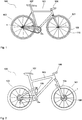
- FIG. 1 is shown as a touring or racing bike bike 100, which is equipped with hubs 1 according to the invention.
- the bike 100 in FIG. 1 has a front wheel 101 and a rear wheel 102, which are held on a frame 103. Furthermore, a handlebar 106 and a saddle 107 is provided. On the front wheel 101 and the rear wheel 102, a rim 110 is provided in each case, which is connected via spokes 109 to the hub 1.
- a radial lock is provided, while at the rear wheel the spokes are at least partially tangentially disposed on the hub to allow the transmission of torque.
- FIG. 2 is a schematic representation of a mountain bike as a bicycle 100 shown, which also has a front wheel 101 and a rear wheel 102 has.
- the Front wheel is held spring loaded on a fork 104, while for the damping of the rear wheel, a damper 105 is available.
- a disc brake 108 serves to effectively brake the bicycle 100.
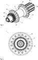
- FIG. 3 shows a perspective view of a designed as a rear hub according to the invention hub 1 for z. B. the bicycle 100 after Fig. 1 or Fig. 2 ,
- the hub 1 has a central part 5 as a hub shell, wherein the hub shell 5 is attached to two end units 3 and 4.
- the end units 3 and 4 have hub flanges 23 and 24, respectively, which are provided with spoke holes 27 for connecting the hub 1 via spokes 109 to a rim 110.
- adapters 33 and 34 are provided at the axial ends of the hub 1, with which the hub 1 is attached to the dropouts of the frame 103.
- the disc brake receptacle 26 serves for fastening a disc brake 108.
- FIG. 4 shows a side view of the hub according to FIG. 3 wherein the hub flange 23 is recognizable on the end unit 3 with the spoke holes 27.
- FIG. 5 is a cross section through the hub 1 shown.
- the hub shell or the central part 5 consists here of a fiber composite material and forms a light yet high-strength connection between the end units 3 and 4 of the hub first
- the hub 1 is rotatably received via bearings 28 relative to the axis 30 designed as a hollow axis.
- the hollow shaft 30 may consist of a metallic alloy and in particular a light metal, but may also consist of at least one or more fiber composite materials.
- the end units 3 and 4 are preferably at least in Essentially of a light metal alloy, but may also be partially or entirely made of fiber composite material.
- the rotor 25 is arranged, which serves to receive one or more pinions.
- the structure of the hub 1 according to the invention is here such that the components used for storage are provided on the end units 3 and 4, so that the hub shell serves as a middle part 5 as a light but firm spacer.
- overlapping areas 8 are provided at both axial ends of the central part 5, at which Einsteckabête 6 of the end units 3 and 4 cooperate with Aufsteckabroughen 7 of the hub shell 5.
- the insertion section 6 of an end unit 3, 4 is inserted into the slip-on section 7 of the hub shell, after a one-component, two-component or multi-component adhesive has been introduced onto the insertion section or into the slip-on section in order to permanently secure connection of the hub shell 5 to the respective one To ensure end unit 3 or 4.
- a toothed disk freewheel 29 is provided as a freewheel, which ensures safe operation via two toothed disks provided with serrations.
- FIG. 6 is an enlarged view of the detail "X" off FIG. 5 shown, wherein a part of the overlap region 8 is shown with the central part 5 and the end unit 3 in cross section.
- a guide section 9 and an adhesive section 10 are provided on the overlapping area 8, wherein the accuracy of fit of the insertion section 6 and the attachment section 7 in the guide section 9 is considerably greater than in the adhesive section 10.
- the adhesive section 10 is a defined radial gap between the insertion portion 6 and the Aufsteckabêt 7 is provided. The gap ensures the defined application of an adhesive layer, so that a permanently secure fit of the middle part 5 can be ensured at the end unit 3.
- a considerable advantage of the construction is that the adhesive area 10 provided axially further inside ensures a reliable adhesive bond between the middle part 5 and the end units 3 and 4, while the guide section 9 or the guide sections 9 provided at both ends 35, 36 of the middle part 5 ensure a defined fit during installation, so that a complex adjustment when gluing the individual housing parts can be omitted.
- FIG. 7 shows a front hub as inventive hub 1 in a cross section.
- the hub 1 has end units 3 and 4 and a middle part 5 arranged therebetween.
- the hub flange 23 is provided on the end unit 3 and the hub flange 24 on the end unit 4.
- Adapters 33 and 34 close to the two ends of the end units 3 and 4, to ensure the inclusion of the front hub 1 on a fork or spring fork 104.
- Overlap areas 8 are provided at the two axial ends 35, 36 of the middle part 5, on which respective insertion sections 6 protrude into the slip-on sections 7 of the hub shell 5.
- the overlapping region 8 extends over an axial width 32, which is composed of the axial width 37 of the guide section 9 and the axial width 38 of the adhesive section 10.
- FIG. 8 shows the detail "X" FIG. 7 greatly enlarged.
- the guide portion 9 extends over an axial width 37 and the adhesive portion 10 extends over an axial Width 38, which together give the axial width 32.
- the axial width 37 of the guide portion 9 here is about 2 mm, the axial width of the adhesive portion 10 in the illustrated embodiment may be between about 5 and 10 mm. This ensures a secure adhesive connection.
- FIGS. 9 to 12 Different variants are shown how an end unit 3 or 4 can be connected to a middle part 5.
- Fig. 9 is a schematic representation of the basic connection according to the FIGS. 6 and 8 shown. It can be clearly seen that two different diameter regions 13 and 14 are provided on the insertion section 6 of the end unit 3. At the guide portion 9, the insertion portion 6 has a larger outer diameter 13 than the smaller outer diameter 14 of the Einsteckabitess 6.
- the inner diameter 15 of the middle part 5 is constant here over the overlap region 8.
- the inner diameter 15 of the central part 5 is constant over its entire length here. Is marked in FIG. 9
- Fig. 10 shows a variant in which also two diameter sections with different outer diameters 13 and 14 are provided on the insertion portion 6 of the end unit 3 and 4, respectively.
- the enlarged outer diameter portion 13 is not provided at the axially outer end of the overlapping portion 8 but at the axially inner end of the overlapping portion 8.
- FIG. 9 has compared to the variant Fig. 10 the advantage that the distances of the guide portions 9 are larger at both ends of the central part 5, so that the same accuracy can be achieved with less effort, as in the embodiment according to Fig. 10 ,
- Fig. 11 another variant is shown in which the insertion portion 6 of the end unit 3 has a constant outside diameter 18.
- the Aufsteckabêt 7 of the middle part 5 has here a reduced inner diameter 17 on the guide portion 9.
- the reduced inner diameter 17 is realized here by a sleeve 20, which may be embodied for example as a metallic sleeve.
- the sleeve 20 may be glued into the interior of the central part 5, but may also be incorporated directly in the manufacture of the central part 5.
- the sleeve 20 is disposed at the axially outer end, as shown in FIG Fig. 11 is shown. But it is also possible to arrange the sleeve 20 axially inside, so that a structure as in Fig. 10 results.
- Fig. 12 shows a variant in which the Aufsteckabites has two diameter portions 15 and 16.
- the area with reduced inner diameter 17 is made in one piece with the hub shell 5.
- the diameter difference 19 which is also present in the embodiments according to the other figures.
- the diameter difference is about 0.1 to 0.3, and preferably about 0.2 mm.
- a hub in which the middle part is inserted on at least one side in an end piece and not attached to it.
- two plug sections are provided.
- An insertion portion has an end of the central portion and on the hub shell and the end unit is formed a Aufsteckabêt.
- Both axial ends of the central part can be identical or different in all embodiments.
- two plug-in sections cooperate, one of which is designed as a plug-in section and one as a slip-on section.
- a guide section and an adhesive section are provided.
- the invention provides an advantageous hub that combines high stability with a low weight.
- the production is simple and due to the overlap region of the male and the slip-on and by the guide portion a particularly high level of ease of assembly and accuracy can be achieved.
Landscapes
- Engineering & Computer Science (AREA)
- Mechanical Engineering (AREA)
- Axle Suspensions And Sidecars For Cycles (AREA)
- Braking Arrangements (AREA)
- Standing Axle, Rod, Or Tube Structures Coupled By Welding, Adhesion, Or Deposition (AREA)
Applications Claiming Priority (1)
| Application Number | Priority Date | Filing Date | Title |
|---|---|---|---|
| DE102011013536A DE102011013536A1 (de) | 2011-03-10 | 2011-03-10 | Nabe für ein Fahrrad |
Publications (2)
| Publication Number | Publication Date |
|---|---|
| EP2497652A1 true EP2497652A1 (fr) | 2012-09-12 |
| EP2497652B1 EP2497652B1 (fr) | 2015-05-06 |
Family
ID=45851367
Family Applications (1)
| Application Number | Title | Priority Date | Filing Date |
|---|---|---|---|
| EP20120001555 Active EP2497652B1 (fr) | 2011-03-10 | 2012-03-07 | Moyeu pour un vélo |
Country Status (3)
| Country | Link |
|---|---|
| US (1) | US9010875B2 (fr) |
| EP (1) | EP2497652B1 (fr) |
| DE (1) | DE102011013536A1 (fr) |
Families Citing this family (15)
| Publication number | Priority date | Publication date | Assignee | Title |
|---|---|---|---|---|
| EP2777945A2 (fr) * | 2013-03-14 | 2014-09-17 | Chosen Co., Ltd. | Ensemble de moyeu de bicyclette |
| DE102013013819A1 (de) * | 2013-08-22 | 2015-02-26 | Dt Swiss Ag | Schnellspanner |
| DE102014117145A1 (de) * | 2014-11-24 | 2016-05-25 | Dt Swiss Ag | Fahrradkomponente mit einem Endanschlag und Endanschlag |
| US11400754B2 (en) * | 2016-07-26 | 2022-08-02 | Dt Swiss Inc. | Hub, in particular for bicycles |
| US10933691B2 (en) | 2017-07-26 | 2021-03-02 | Dt Swiss Inc. | Hub, in particular for bicycles |
| US10442245B2 (en) * | 2016-07-26 | 2019-10-15 | Dt Swiss Inc. | Hub, in particular for bicycles |
| DE102017116948A1 (de) * | 2016-07-26 | 2018-02-01 | Dt Swiss Ag | Nabe insbesondere für Fahrräder |
| US10995806B2 (en) | 2017-07-26 | 2021-05-04 | Dt Swiss Inc. | Hub, in particular for bicycles |
| US10625540B2 (en) | 2017-07-26 | 2020-04-21 | Dt Swiss Inc. | Hub, in particular for bicycles |
| TWI868953B (zh) * | 2017-05-30 | 2025-01-01 | 日商島野股份有限公司 | 自行車後輪轂總成及鏈輪支撐主體 |
| US10752320B2 (en) | 2017-09-22 | 2020-08-25 | Shimano Inc. | Bicycle rear hub assembly |
| US11059541B2 (en) | 2017-05-30 | 2021-07-13 | Shimano Inc. | Bicycle hub assembly |
| US10946931B2 (en) | 2017-09-22 | 2021-03-16 | Shimano Inc. | Bicycle rear sprocket assembly and bicycle drive train |
| US11332213B2 (en) | 2017-05-30 | 2022-05-17 | Shimano Inc. | Bicycle rear sprocket assembly and bicycle drive train |
| US12138958B2 (en) | 2021-12-22 | 2024-11-12 | Giant Manufacturing Co., Ltd. | Hub structure and hub for a bicycle |
Citations (5)
| Publication number | Priority date | Publication date | Assignee | Title |
|---|---|---|---|---|
| DE4430565A1 (de) * | 1994-08-30 | 1996-03-07 | Anton Link | Radlager für die Räder eines Fahrzeugs, insbesondere eines Fahrrads |
| US20010005098A1 (en) * | 1999-12-23 | 2001-06-28 | Mavic S.A. | Hub for a spoked wheel, such as a bicycle wheel |
| CN201538196U (zh) * | 2009-12-08 | 2010-08-04 | 胡伟 | 防震式自行车轮毂总成 |
| DE202010000533U1 (de) * | 2009-08-26 | 2010-08-12 | Talon Engineering Ltd., Yeovil | Radnabe |
| CN201646249U (zh) * | 2010-03-19 | 2010-11-24 | 胡伟 | 防震整体式自行车轮毂总成 |
Family Cites Families (5)
| Publication number | Priority date | Publication date | Assignee | Title |
|---|---|---|---|---|
| US3170549A (en) * | 1961-06-23 | 1965-02-23 | Gregory Ind | Bicycle coaster brake |
| DE2927138A1 (de) * | 1979-07-05 | 1981-01-08 | Union Sils Van De Loo & Co | Radnabengehaeuse, insbesondere fuer fahrraeder |
| US5433306A (en) * | 1993-03-11 | 1995-07-18 | Yang; Shu-Chiung C. | Hub assembly for a bicycle |
| DE9403506U1 (de) * | 1994-03-02 | 1994-04-28 | Friedrich, Peter, 35435 Wettenberg | Fahrradnabe |
| US7562755B2 (en) * | 2006-07-07 | 2009-07-21 | Dt Swiss, Inc. | Rear wheel hub, in particular for bicycles |
-
2011
- 2011-03-10 DE DE102011013536A patent/DE102011013536A1/de not_active Withdrawn
-
2012
- 2012-03-07 EP EP20120001555 patent/EP2497652B1/fr active Active
- 2012-03-09 US US13/416,059 patent/US9010875B2/en active Active
Patent Citations (5)
| Publication number | Priority date | Publication date | Assignee | Title |
|---|---|---|---|---|
| DE4430565A1 (de) * | 1994-08-30 | 1996-03-07 | Anton Link | Radlager für die Räder eines Fahrzeugs, insbesondere eines Fahrrads |
| US20010005098A1 (en) * | 1999-12-23 | 2001-06-28 | Mavic S.A. | Hub for a spoked wheel, such as a bicycle wheel |
| DE202010000533U1 (de) * | 2009-08-26 | 2010-08-12 | Talon Engineering Ltd., Yeovil | Radnabe |
| CN201538196U (zh) * | 2009-12-08 | 2010-08-04 | 胡伟 | 防震式自行车轮毂总成 |
| CN201646249U (zh) * | 2010-03-19 | 2010-11-24 | 胡伟 | 防震整体式自行车轮毂总成 |
Also Published As
| Publication number | Publication date |
|---|---|
| US20120228922A1 (en) | 2012-09-13 |
| EP2497652B1 (fr) | 2015-05-06 |
| US9010875B2 (en) | 2015-04-21 |
| DE102011013536A1 (de) | 2012-09-13 |
Similar Documents
| Publication | Publication Date | Title |
|---|---|---|
| EP2497652B1 (fr) | Moyeu pour un vélo | |
| DE102012017115B4 (de) | Fahrradvorderradnabe mit Torsionsrohr | |
| EP2221192B1 (fr) | Composant de moyeu de vélo doté d'un rotor comportant une dentelure frontale | |
| DE102017116945A1 (de) | Nabe insbesondere für Fahrräder | |
| DE102012016608A1 (de) | Antriebsnabe | |
| EP2559567A2 (fr) | Composant de vélo et procédé de montage d'un composant de vélo | |
| DE102011015962B4 (de) | Nabe für ein Fahrrad | |
| DE102011110199A1 (de) | Nabe | |
| EP2100806A1 (fr) | Composant de bicyclette | |
| EP3275693B1 (fr) | Moyeu, en particulier pour vélos | |
| EP3023325A1 (fr) | Composant de vélo comprenant une butée et butée | |
| DE102018101725A1 (de) | Nabe | |
| EP3862194A1 (fr) | Moyeu, en particulier pour bicyclettes | |
| DE102018101720A1 (de) | Nabe insbesondere für Fahrräder | |
| DE102014105049A1 (de) | Gabelkomponente für ein wenigstens teilweise muskelbetriebenes Fahrrad | |
| DE102011111487A1 (de) | Nabe | |
| DE102007026821B4 (de) | Nabe, insbesondere für Fahrräder und dergleichen | |
| EP3238951B1 (fr) | Moyeu et roue | |
| EP4368411B1 (fr) | Moyeu, en particulier pour bicyclettes | |
| EP4368850B1 (fr) | Moyeu, en particulier pour bicyclettes | |
| EP4379228B1 (fr) | Moyeu, en particulier pour bicyclettes | |
| DE102024107443A1 (de) | Nabe insbesondere für Fahrräder | |
| DE102022129568A1 (de) | Nabe und Rotor insbesondere für Fahrräder | |
| EP4707148A1 (fr) | Composant de bicyclette |
Legal Events
| Date | Code | Title | Description |
|---|---|---|---|
| PUAI | Public reference made under article 153(3) epc to a published international application that has entered the european phase |
Free format text: ORIGINAL CODE: 0009012 |
|
| AK | Designated contracting states |
Kind code of ref document: A1 Designated state(s): AL AT BE BG CH CY CZ DE DK EE ES FI FR GB GR HR HU IE IS IT LI LT LU LV MC MK MT NL NO PL PT RO RS SE SI SK SM TR |
|
| AX | Request for extension of the european patent |
Extension state: BA ME |
|
| 17P | Request for examination filed |
Effective date: 20130221 |
|
| REG | Reference to a national code |
Ref country code: DE Ref legal event code: R079 Ref document number: 502012003021 Country of ref document: DE Free format text: PREVIOUS MAIN CLASS: B60B0027020000 Ipc: B60B0027040000 |
|
| GRAP | Despatch of communication of intention to grant a patent |
Free format text: ORIGINAL CODE: EPIDOSNIGR1 |
|
| RIC1 | Information provided on ipc code assigned before grant |
Ipc: B60B 27/04 20060101AFI20141030BHEP |
|
| INTG | Intention to grant announced |
Effective date: 20141121 |
|
| GRAS | Grant fee paid |
Free format text: ORIGINAL CODE: EPIDOSNIGR3 |
|
| GRAA | (expected) grant |
Free format text: ORIGINAL CODE: 0009210 |
|
| AK | Designated contracting states |
Kind code of ref document: B1 Designated state(s): AL AT BE BG CH CY CZ DE DK EE ES FI FR GB GR HR HU IE IS IT LI LT LU LV MC MK MT NL NO PL PT RO RS SE SI SK SM TR |
|
| REG | Reference to a national code |
Ref country code: GB Ref legal event code: FG4D Free format text: NOT ENGLISH |
|
| REG | Reference to a national code |
Ref country code: CH Ref legal event code: EP |
|
| REG | Reference to a national code |
Ref country code: IE Ref legal event code: FG4D Free format text: LANGUAGE OF EP DOCUMENT: GERMAN |
|
| REG | Reference to a national code |
Ref country code: AT Ref legal event code: REF Ref document number: 725426 Country of ref document: AT Kind code of ref document: T Effective date: 20150615 |
|
| REG | Reference to a national code |
Ref country code: DE Ref legal event code: R096 Ref document number: 502012003021 Country of ref document: DE Effective date: 20150618 |
|
| REG | Reference to a national code |
Ref country code: NL Ref legal event code: MP Effective date: 20150506 |
|
| REG | Reference to a national code |
Ref country code: LT Ref legal event code: MG4D |
|
| PG25 | Lapsed in a contracting state [announced via postgrant information from national office to epo] |
Ref country code: NO Free format text: LAPSE BECAUSE OF FAILURE TO SUBMIT A TRANSLATION OF THE DESCRIPTION OR TO PAY THE FEE WITHIN THE PRESCRIBED TIME-LIMIT Effective date: 20150806 Ref country code: PT Free format text: LAPSE BECAUSE OF FAILURE TO SUBMIT A TRANSLATION OF THE DESCRIPTION OR TO PAY THE FEE WITHIN THE PRESCRIBED TIME-LIMIT Effective date: 20150907 Ref country code: HR Free format text: LAPSE BECAUSE OF FAILURE TO SUBMIT A TRANSLATION OF THE DESCRIPTION OR TO PAY THE FEE WITHIN THE PRESCRIBED TIME-LIMIT Effective date: 20150506 Ref country code: FI Free format text: LAPSE BECAUSE OF FAILURE TO SUBMIT A TRANSLATION OF THE DESCRIPTION OR TO PAY THE FEE WITHIN THE PRESCRIBED TIME-LIMIT Effective date: 20150506 Ref country code: ES Free format text: LAPSE BECAUSE OF FAILURE TO SUBMIT A TRANSLATION OF THE DESCRIPTION OR TO PAY THE FEE WITHIN THE PRESCRIBED TIME-LIMIT Effective date: 20150506 Ref country code: LT Free format text: LAPSE BECAUSE OF FAILURE TO SUBMIT A TRANSLATION OF THE DESCRIPTION OR TO PAY THE FEE WITHIN THE PRESCRIBED TIME-LIMIT Effective date: 20150506 |
|
| PG25 | Lapsed in a contracting state [announced via postgrant information from national office to epo] |
Ref country code: GR Free format text: LAPSE BECAUSE OF FAILURE TO SUBMIT A TRANSLATION OF THE DESCRIPTION OR TO PAY THE FEE WITHIN THE PRESCRIBED TIME-LIMIT Effective date: 20150807 Ref country code: BG Free format text: LAPSE BECAUSE OF FAILURE TO SUBMIT A TRANSLATION OF THE DESCRIPTION OR TO PAY THE FEE WITHIN THE PRESCRIBED TIME-LIMIT Effective date: 20150806 Ref country code: RS Free format text: LAPSE BECAUSE OF FAILURE TO SUBMIT A TRANSLATION OF THE DESCRIPTION OR TO PAY THE FEE WITHIN THE PRESCRIBED TIME-LIMIT Effective date: 20150506 Ref country code: LV Free format text: LAPSE BECAUSE OF FAILURE TO SUBMIT A TRANSLATION OF THE DESCRIPTION OR TO PAY THE FEE WITHIN THE PRESCRIBED TIME-LIMIT Effective date: 20150506 Ref country code: IS Free format text: LAPSE BECAUSE OF FAILURE TO SUBMIT A TRANSLATION OF THE DESCRIPTION OR TO PAY THE FEE WITHIN THE PRESCRIBED TIME-LIMIT Effective date: 20150906 |
|
| PG25 | Lapsed in a contracting state [announced via postgrant information from national office to epo] |
Ref country code: EE Free format text: LAPSE BECAUSE OF FAILURE TO SUBMIT A TRANSLATION OF THE DESCRIPTION OR TO PAY THE FEE WITHIN THE PRESCRIBED TIME-LIMIT Effective date: 20150506 Ref country code: DK Free format text: LAPSE BECAUSE OF FAILURE TO SUBMIT A TRANSLATION OF THE DESCRIPTION OR TO PAY THE FEE WITHIN THE PRESCRIBED TIME-LIMIT Effective date: 20150506 |
|
| REG | Reference to a national code |
Ref country code: DE Ref legal event code: R097 Ref document number: 502012003021 Country of ref document: DE |
|
| PG25 | Lapsed in a contracting state [announced via postgrant information from national office to epo] |
Ref country code: RO Free format text: LAPSE BECAUSE OF NON-PAYMENT OF DUE FEES Effective date: 20150506 Ref country code: CZ Free format text: LAPSE BECAUSE OF FAILURE TO SUBMIT A TRANSLATION OF THE DESCRIPTION OR TO PAY THE FEE WITHIN THE PRESCRIBED TIME-LIMIT Effective date: 20150506 Ref country code: PL Free format text: LAPSE BECAUSE OF FAILURE TO SUBMIT A TRANSLATION OF THE DESCRIPTION OR TO PAY THE FEE WITHIN THE PRESCRIBED TIME-LIMIT Effective date: 20150506 Ref country code: SK Free format text: LAPSE BECAUSE OF FAILURE TO SUBMIT A TRANSLATION OF THE DESCRIPTION OR TO PAY THE FEE WITHIN THE PRESCRIBED TIME-LIMIT Effective date: 20150506 |
|
| PLBE | No opposition filed within time limit |
Free format text: ORIGINAL CODE: 0009261 |
|
| STAA | Information on the status of an ep patent application or granted ep patent |
Free format text: STATUS: NO OPPOSITION FILED WITHIN TIME LIMIT |
|
| 26N | No opposition filed |
Effective date: 20160209 |
|
| PG25 | Lapsed in a contracting state [announced via postgrant information from national office to epo] |
Ref country code: IT Free format text: LAPSE BECAUSE OF FAILURE TO SUBMIT A TRANSLATION OF THE DESCRIPTION OR TO PAY THE FEE WITHIN THE PRESCRIBED TIME-LIMIT Effective date: 20150506 |
|
| PG25 | Lapsed in a contracting state [announced via postgrant information from national office to epo] |
Ref country code: SI Free format text: LAPSE BECAUSE OF FAILURE TO SUBMIT A TRANSLATION OF THE DESCRIPTION OR TO PAY THE FEE WITHIN THE PRESCRIBED TIME-LIMIT Effective date: 20150506 |
|
| PG25 | Lapsed in a contracting state [announced via postgrant information from national office to epo] |
Ref country code: BE Free format text: LAPSE BECAUSE OF NON-PAYMENT OF DUE FEES Effective date: 20160331 |
|
| PG25 | Lapsed in a contracting state [announced via postgrant information from national office to epo] |
Ref country code: MC Free format text: LAPSE BECAUSE OF FAILURE TO SUBMIT A TRANSLATION OF THE DESCRIPTION OR TO PAY THE FEE WITHIN THE PRESCRIBED TIME-LIMIT Effective date: 20150506 Ref country code: LU Free format text: LAPSE BECAUSE OF FAILURE TO SUBMIT A TRANSLATION OF THE DESCRIPTION OR TO PAY THE FEE WITHIN THE PRESCRIBED TIME-LIMIT Effective date: 20160307 |
|
| REG | Reference to a national code |
Ref country code: CH Ref legal event code: PL |
|
| GBPC | Gb: european patent ceased through non-payment of renewal fee |
Effective date: 20160307 |
|
| REG | Reference to a national code |
Ref country code: IE Ref legal event code: MM4A |
|
| REG | Reference to a national code |
Ref country code: FR Ref legal event code: ST Effective date: 20161130 |
|
| PG25 | Lapsed in a contracting state [announced via postgrant information from national office to epo] |
Ref country code: LI Free format text: LAPSE BECAUSE OF NON-PAYMENT OF DUE FEES Effective date: 20160331 Ref country code: GB Free format text: LAPSE BECAUSE OF NON-PAYMENT OF DUE FEES Effective date: 20160307 Ref country code: CH Free format text: LAPSE BECAUSE OF NON-PAYMENT OF DUE FEES Effective date: 20160331 Ref country code: IE Free format text: LAPSE BECAUSE OF NON-PAYMENT OF DUE FEES Effective date: 20160307 Ref country code: FR Free format text: LAPSE BECAUSE OF NON-PAYMENT OF DUE FEES Effective date: 20160331 |
|
| PG25 | Lapsed in a contracting state [announced via postgrant information from national office to epo] |
Ref country code: SE Free format text: LAPSE BECAUSE OF FAILURE TO SUBMIT A TRANSLATION OF THE DESCRIPTION OR TO PAY THE FEE WITHIN THE PRESCRIBED TIME-LIMIT Effective date: 20150506 Ref country code: NL Free format text: LAPSE BECAUSE OF FAILURE TO SUBMIT A TRANSLATION OF THE DESCRIPTION OR TO PAY THE FEE WITHIN THE PRESCRIBED TIME-LIMIT Effective date: 20150506 |
|
| PG25 | Lapsed in a contracting state [announced via postgrant information from national office to epo] |
Ref country code: MT Free format text: LAPSE BECAUSE OF FAILURE TO SUBMIT A TRANSLATION OF THE DESCRIPTION OR TO PAY THE FEE WITHIN THE PRESCRIBED TIME-LIMIT Effective date: 20150506 |
|
| REG | Reference to a national code |
Ref country code: AT Ref legal event code: MM01 Ref document number: 725426 Country of ref document: AT Kind code of ref document: T Effective date: 20170307 |
|
| PG25 | Lapsed in a contracting state [announced via postgrant information from national office to epo] |
Ref country code: CY Free format text: LAPSE BECAUSE OF FAILURE TO SUBMIT A TRANSLATION OF THE DESCRIPTION OR TO PAY THE FEE WITHIN THE PRESCRIBED TIME-LIMIT Effective date: 20150506 Ref country code: HU Free format text: LAPSE BECAUSE OF FAILURE TO SUBMIT A TRANSLATION OF THE DESCRIPTION OR TO PAY THE FEE WITHIN THE PRESCRIBED TIME-LIMIT; INVALID AB INITIO Effective date: 20120307 Ref country code: SM Free format text: LAPSE BECAUSE OF FAILURE TO SUBMIT A TRANSLATION OF THE DESCRIPTION OR TO PAY THE FEE WITHIN THE PRESCRIBED TIME-LIMIT Effective date: 20150506 |
|
| PG25 | Lapsed in a contracting state [announced via postgrant information from national office to epo] |
Ref country code: MK Free format text: LAPSE BECAUSE OF FAILURE TO SUBMIT A TRANSLATION OF THE DESCRIPTION OR TO PAY THE FEE WITHIN THE PRESCRIBED TIME-LIMIT Effective date: 20150506 Ref country code: TR Free format text: LAPSE BECAUSE OF FAILURE TO SUBMIT A TRANSLATION OF THE DESCRIPTION OR TO PAY THE FEE WITHIN THE PRESCRIBED TIME-LIMIT Effective date: 20150506 |
|
| PG25 | Lapsed in a contracting state [announced via postgrant information from national office to epo] |
Ref country code: AT Free format text: LAPSE BECAUSE OF NON-PAYMENT OF DUE FEES Effective date: 20170307 |
|
| PG25 | Lapsed in a contracting state [announced via postgrant information from national office to epo] |
Ref country code: AL Free format text: LAPSE BECAUSE OF FAILURE TO SUBMIT A TRANSLATION OF THE DESCRIPTION OR TO PAY THE FEE WITHIN THE PRESCRIBED TIME-LIMIT Effective date: 20150506 |
|
| P01 | Opt-out of the competence of the unified patent court (upc) registered |
Effective date: 20230517 |
|
| PGFP | Annual fee paid to national office [announced via postgrant information from national office to epo] |
Ref country code: DE Payment date: 20260326 Year of fee payment: 15 |