EP2500500A2 - Système d'entraînement et de guidage pour portes, notamment pour portes de véhicule d'un véhicule de transport de personnes, ouverture d'entrée et de sortie d'un véhicule de transport de personnes et véhicule de transport de personnes - Google Patents
Système d'entraînement et de guidage pour portes, notamment pour portes de véhicule d'un véhicule de transport de personnes, ouverture d'entrée et de sortie d'un véhicule de transport de personnes et véhicule de transport de personnes Download PDFInfo
- Publication number
- EP2500500A2 EP2500500A2 EP12160186A EP12160186A EP2500500A2 EP 2500500 A2 EP2500500 A2 EP 2500500A2 EP 12160186 A EP12160186 A EP 12160186A EP 12160186 A EP12160186 A EP 12160186A EP 2500500 A2 EP2500500 A2 EP 2500500A2
- Authority
- EP
- European Patent Office
- Prior art keywords
- drive
- guide
- carriage
- guide rail
- driver
- Prior art date
- Legal status (The legal status is an assumption and is not a legal conclusion. Google has not performed a legal analysis and makes no representation as to the accuracy of the status listed.)
- Withdrawn
Links
- 230000005540 biological transmission Effects 0.000 claims description 5
- 230000001419 dependent effect Effects 0.000 description 2
- 238000011161 development Methods 0.000 description 2
- 230000018109 developmental process Effects 0.000 description 2
- 230000000694 effects Effects 0.000 description 2
- 230000002411 adverse Effects 0.000 description 1
- 238000006073 displacement reaction Methods 0.000 description 1
- 238000000034 method Methods 0.000 description 1
Images

Classifications
-
- E—FIXED CONSTRUCTIONS
- E05—LOCKS; KEYS; WINDOW OR DOOR FITTINGS; SAFES
- E05D—HINGES OR SUSPENSION DEVICES FOR DOORS, WINDOWS OR WINGS
- E05D15/00—Suspension arrangements for wings
- E05D15/06—Suspension arrangements for wings for wings sliding horizontally more or less in their own plane
- E05D15/10—Suspension arrangements for wings for wings sliding horizontally more or less in their own plane movable out of one plane into a second parallel plane
- E05D15/1065—Suspension arrangements for wings for wings sliding horizontally more or less in their own plane movable out of one plane into a second parallel plane with transversely moving track
- E05D15/1068—Suspension arrangements for wings for wings sliding horizontally more or less in their own plane movable out of one plane into a second parallel plane with transversely moving track specially adapted for use in railway-cars or mass transit vehicles
-
- E—FIXED CONSTRUCTIONS
- E05—LOCKS; KEYS; WINDOW OR DOOR FITTINGS; SAFES
- E05F—DEVICES FOR MOVING WINGS INTO OPEN OR CLOSED POSITION; CHECKS FOR WINGS; WING FITTINGS NOT OTHERWISE PROVIDED FOR, CONCERNED WITH THE FUNCTIONING OF THE WING
- E05F15/00—Power-operated mechanisms for wings
- E05F15/60—Power-operated mechanisms for wings using electrical actuators
- E05F15/603—Power-operated mechanisms for wings using electrical actuators using rotary electromotors
- E05F15/632—Power-operated mechanisms for wings using electrical actuators using rotary electromotors for horizontally-sliding wings
- E05F15/635—Power-operated mechanisms for wings using electrical actuators using rotary electromotors for horizontally-sliding wings operated by push-pull mechanisms, e.g. flexible or rigid rack-and-pinion arrangements
-
- E—FIXED CONSTRUCTIONS
- E05—LOCKS; KEYS; WINDOW OR DOOR FITTINGS; SAFES
- E05F—DEVICES FOR MOVING WINGS INTO OPEN OR CLOSED POSITION; CHECKS FOR WINGS; WING FITTINGS NOT OTHERWISE PROVIDED FOR, CONCERNED WITH THE FUNCTIONING OF THE WING
- E05F15/00—Power-operated mechanisms for wings
- E05F15/60—Power-operated mechanisms for wings using electrical actuators
- E05F15/603—Power-operated mechanisms for wings using electrical actuators using rotary electromotors
- E05F15/632—Power-operated mechanisms for wings using electrical actuators using rotary electromotors for horizontally-sliding wings
- E05F15/635—Power-operated mechanisms for wings using electrical actuators using rotary electromotors for horizontally-sliding wings operated by push-pull mechanisms, e.g. flexible or rigid rack-and-pinion arrangements
- E05F15/638—Power-operated mechanisms for wings using electrical actuators using rotary electromotors for horizontally-sliding wings operated by push-pull mechanisms, e.g. flexible or rigid rack-and-pinion arrangements allowing or involving a secondary movement of the wing, e.g. rotational or transversal
-
- E—FIXED CONSTRUCTIONS
- E05—LOCKS; KEYS; WINDOW OR DOOR FITTINGS; SAFES
- E05F—DEVICES FOR MOVING WINGS INTO OPEN OR CLOSED POSITION; CHECKS FOR WINGS; WING FITTINGS NOT OTHERWISE PROVIDED FOR, CONCERNED WITH THE FUNCTIONING OF THE WING
- E05F15/00—Power-operated mechanisms for wings
- E05F15/60—Power-operated mechanisms for wings using electrical actuators
- E05F15/603—Power-operated mechanisms for wings using electrical actuators using rotary electromotors
- E05F15/632—Power-operated mechanisms for wings using electrical actuators using rotary electromotors for horizontally-sliding wings
- E05F15/655—Power-operated mechanisms for wings using electrical actuators using rotary electromotors for horizontally-sliding wings specially adapted for vehicle wings
-
- E—FIXED CONSTRUCTIONS
- E05—LOCKS; KEYS; WINDOW OR DOOR FITTINGS; SAFES
- E05Y—INDEXING SCHEME ASSOCIATED WITH SUBCLASSES E05D AND E05F, RELATING TO CONSTRUCTION ELEMENTS, ELECTRIC CONTROL, POWER SUPPLY, POWER SIGNAL OR TRANSMISSION, USER INTERFACES, MOUNTING OR COUPLING, DETAILS, ACCESSORIES, AUXILIARY OPERATIONS NOT OTHERWISE PROVIDED FOR, APPLICATION THEREOF
- E05Y2900/00—Application of doors, windows, wings or fittings thereof
- E05Y2900/50—Application of doors, windows, wings or fittings thereof for vehicles
- E05Y2900/51—Application of doors, windows, wings or fittings thereof for vehicles for railway cars or mass transit vehicles
Definitions
- the invention relates to a drive and guide system for doors, in particular for vehicle doors of a passenger transport vehicle. Furthermore, the invention relates to an entry and exit opening with such a drive and guide system and an associated passenger transport vehicle.
- pivot sliding doors which have a guide system based on the telescopic principle.
- the utility model publication DE 20 2009 010 695 U1 a door in which the maximum displacement of the door leaf is increased by the fact that between the door leaf and a rail on the portal, a carriage is provided with a gear which comprises a gear and two racks.
- a first runner of the carriage is motorized along the rail movable, and the door is slidably mounted relative to the first runner.
- the fulcrum between the drive and the door for tolerance compensation is often close to the door leaf in this or similar solutions, so that a high torque (M) is created by the door weight around the longitudinal axis of the guide rails, which may require a complex guide system.
- the object of the invention in the reduction of the torque to guide systems for door leaf drive devices with telescopic door.
- this object is achieved by a drive and guide system according to the independent claim 1.
- Advantageous developments of this drive and guide system will become apparent from the dependent claims 2-13.
- the object is further achieved by an entry and exit opening for passenger transport vehicles according to claim 14 and an associated passenger transport vehicle according to claim 15.
- the drive and guide system according to the invention for doors comprises at least one door leaf and a carriage, which is guided between two parallel guide rails, wherein a first guide rail along the second guide rail is movable and the door leaf at the first Guide rail is attached.
- the two guide rails and the carriage are coupled to each other via a gear that a motor-driven movement of the carriage along the second guide rail causes a relative movement of the first guide rail along the second guide rail.
- the second guide rail is articulated by a main hinge on the vehicle, wherein the axis of rotation of the main hinge extends parallel to the longitudinal axes of the guide rails.
- the problem is solved by a main hinge, which reduces the torque M about the longitudinal axes of the guide rails.
- the door leaf can be rotated via the main hinge and all guide components remain torque-free around the longitudinal axis of the drive.
- different contours of the door panel can be displayed without any problem, without having to take into account any torque load of the guide components.
- the transmission used may be formed by at least one gear and two racks, one rack being fixedly connected to each guide rail, while the gear is non-rotatably mounted on the carriage and is meshingly engaged with the two racks. This makes it easy to form a gear, with which the relative movement of the first guide rail can be effected in relation to the second guide rail.
- the carriage is in one embodiment of the invention via a driver motor along the second guide rail movable, wherein the driver is pivotally connected to the carriage to accommodate vertical movements of the door without burdening the drive or guide components with a torque.
- the driver is preferably connected via a hinge to the carriage, wherein the axis of rotation of the hinge extends parallel to the guide rails.
- the main hinge is attached to a drive carrier along which the driver is moved by a motor.
- the driver can then be connected to a carriage, which is movable by motor along the drive carrier.
- the main hinge is preferably mounted directly on this drive carrier, whereby The guide rails are torque-free about their longitudinal axes, since the pivot point between the door drive and door is not as close to the door as other systems, but as close as possible to the drive carrier.
- the driver is coupled via a joint receptacle with a drive.
- the driver may be pivotally connected to the carriage via a spherical bearing, so that the drive or guide components are not burdened by the weight and the movements of the door.
- the guide carriage is movable within a guide along the drive carrier, wherein the guide is firmly connected to the vehicle.
- the carriage is further guided on the drive carrier. This can be represented by rollers on guide rods or any linear guides.
- the motor drive of the driver or the door leaf on the carriage and the first guide rail can be done in various ways. In one embodiment of the invention, it takes place via a drive spindle and a spindle nut. The carriage is then preferably fixedly connected to the spindle nut, whereby it is guided and can not tilt on the spindle.
- a toothed belt may also be provided as drive means.
- the door is designed not only displaceable, but also pivotable.
- the drive carrier is for example rotatably mounted on at least one pivot arm, wherein it is preferably rotatably mounted on two lateral pivot arms.
- the invention further comprises an entry and exit opening for a passenger transport vehicle, comprising at least one door, wherein the entry and exit opening has a described drive and guide system.
- the invention comprises a passenger transport vehicle with at least one such entry and exit opening.
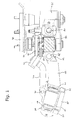
- Fig. 1 is a side view of an embodiment of the drive and guide system according to the invention, while Fig. 2 displays this system in a three-dimensional view.
- the side view corresponds to the Fig. 1 a view from the right to the system according to Fig. 2 , and in both figures, the door to be moved is not explicitly shown.
- An essential component of the drive and guide system is a carriage 10 which has runners 11 and 12 on two opposite sides. These runners 11, 12 are designed so that the carriage 10 can be moved in two parallel guide rails 30 and 31.
- the runners 11, 12 are rollers which are rotatably mounted on the carriage 10 and so can roll within the guide rails 30 and 31.
- the outer contour of the runners 11, 12 and the inner contour of the guide rails 30, 31 are selected so that the runners 11, 12 are held axially in the guide rails 30, 31. This can be done as in the illustrated embodiment by grooves formed in the guide rails 30, 31.
- a door is mounted (not shown) and this guide rail 30 is movable along its longitudinal axis relative to the vehicle, whereby the door can also be moved.
- the other guide rail 31, however, is not movable relative to the vehicle, but is fixed in the direction of its longitudinal axis.
- the inner guide rail 31 via a hinge connection 33 and a main hinge 32 attached to a drive carrier 50.
- the axis of rotation of the main hinge 32 extends substantially parallel to the two guide rails 30, 31, so that the main hinge 32 can receive vertical movements articulated.
- the inner guide rail 31 is fixed in the direction of its longitudinal axis.
- the main hinge 32 is attached directly to the drive carrier 50 and the distance between the drive carrier 50 and the inner guide rail 31 is bridged by the hinge connection 33.
- the bearing via the main hinge 32 is spring-assisted.
- at least one spring between the hinge connection 33 and the drive carrier 31 is mounted, wherein the spring preferably extends below the main hinge 32 so that it is compressed in downward movements of the door leaf in the vertical direction.
- the spring is designed for the forces occurring and thus prevents vibrations directly on the drive carrier 31.
- the bias of the spring can be adjusted by additional nuts to the corresponding door weight.
- the door is not only movable relative to the vehicle, but also pivotable, so that it is a sliding door. Therefore, the drive carrier 50 is rotatably mounted on at least one pivot arm 52, via which the drive carrier 50 is pivotable. From the Fig. 2 It can be seen that the drive carrier 50 is non-rotatably mounted on two lateral pivot arms 52 and 52 '. Thus, when you open the door first swung and then move along the longitudinal axis of the vehicle done.
- the two guide rails 30, 31 are connected to each other via a gear, that a motor-driven movement of the carriage 10 along the first, inner guide rail 31 causes a movement of the second, outer guide rail 30 parallel to the first guide rail 31.
- This transmission can be realized in various ways. However, it has proved to be advantageous to attach to each guide rail 30, 31 in each case a rack 21, 22, wherein the teeth of the two racks 21, 22 are directed inwardly to the carriage 10 out.
- a gear 20 is then mounted rotationally fixed, that meshing with the two racks 21, 22 stands, so that the racks 21, 22 and the gear 20 form the transmission.
- the carriage 10 is movable via a motor-driven driver 40 along the inner guide rail 31.
- the gear 20 meshes with both racks 21, 22 and thus simultaneously causes a relative movement of the outer guide rail 30 with respect to the inner guide rail 31.
- a movement of the door leaf along the vehicle is effected.
- the driver 40 is pivotally connected via a further hinge 41 to the carriage 10 and is connected via a joint receptacle 42 in conjunction with a carriage 60.
- a joint receptacle 42 in conjunction with a carriage 60.
- the joint receptacle 42 is preferably designed as a spherical bearing, so that movements in other directions can be recorded.
- the guide carriage 60 is movably mounted on the drive carrier 50, which can be done for example via rotatable guide elements 63 such as rollers, which roll on two sides of a rail 53 on the drive carrier 50.
- the carriage is also guided via a further guide element 62 in a U-shaped guide 61.
- This guide element 62 may also be a roller.
- the guide can then be attached, for example, to a mounting plate 70, with which the drive and guide system can be mounted on the vehicle.
- the mounting plate 70 may already represent a part of the vehicle body.
- the main hinge 32 may for example consist of several juxtaposed bushes through which a bolt 32 'is guided to form over the entire length of the drive carrier 50, a pivot bearing whose axis of rotation parallel to the drive carrier 50 and the guide rails 30 and 31 runs.
- the hinge connection 33 between the inner guide rail 31 and the main hinge 32 may be made in two parts, so that in Fig. 2 a first hinge connection 33 connects the right-hand region of the guide rail 31 with the drive carrier 50, while a second hinge connection 33 'connects the left-hand region of the guide rail 31 with the drive carrier 50.
- Fig. 2 shows that the outer guide rail 30 may be shorter than the inner guide rail 31. While the length of the inner guide rail 31 corresponds approximately to the length of the drive carrier 50, the outer guide rail 30 must be made only half as long to a telescopic effect unfold. It is in Fig. 2 a closed position of the door shown.
- the two pivot arms 52 and 52 'pivot the drive carrier 50 forwards and the carrier 40 moves the carriage 10 (not shown) driven by a motor to the left, so that a total of one pivoting and shifting operation takes place.
- the carriage 10 can be moved together with the gear 20 only a maximum of the left end of the inner guide rail 31.
- a relative movement of the outer- ⁇ eren guide rail 30 is effected, which can be moved by the gear via this end of the inner guide rail 31 addition.
Landscapes
- Engineering & Computer Science (AREA)
- Mechanical Engineering (AREA)
- Power-Operated Mechanisms For Wings (AREA)
Applications Claiming Priority (1)
| Application Number | Priority Date | Filing Date | Title |
|---|---|---|---|
| DE102011001414 | 2011-03-18 |
Publications (2)
| Publication Number | Publication Date |
|---|---|
| EP2500500A2 true EP2500500A2 (fr) | 2012-09-19 |
| EP2500500A3 EP2500500A3 (fr) | 2014-12-17 |
Family
ID=45888003
Family Applications (1)
| Application Number | Title | Priority Date | Filing Date |
|---|---|---|---|
| EP12160186.8A Withdrawn EP2500500A3 (fr) | 2011-03-18 | 2012-03-19 | Système d'entraînement et de guidage pour portes, notamment pour portes de véhicule d'un véhicule de transport de personnes, ouverture d'entrée et de sortie d'un véhicule de transport de personnes et véhicule de transport de personnes |
Country Status (1)
| Country | Link |
|---|---|
| EP (1) | EP2500500A3 (fr) |
Citations (3)
| Publication number | Priority date | Publication date | Assignee | Title |
|---|---|---|---|---|
| DE10158094A1 (de) | 2001-11-27 | 2003-07-24 | Bode Gmbh & Co Kg | Schwenkschiebetür für Fahrzeuge, insbesondere Fahrgasttür für Fahrzeuge des öffentlichen Personennahverkehrs |
| DE202006015735U1 (de) | 2006-10-13 | 2008-02-21 | Gebr. Bode Gmbh & Co. Kg | Als Schiebetür oder Schwenkschiebetür ausgebildete Fahrgasttür für Fahrzeuge des öffentlichen Personenverkehrs |
| DE202009010695U1 (de) | 2009-08-07 | 2010-12-23 | Gebr. Bode Gmbh & Co. Kg | Türflügelantriebsvorrichtung mit teleskopierendem Türflügel |
Family Cites Families (2)
| Publication number | Priority date | Publication date | Assignee | Title |
|---|---|---|---|---|
| FR2050854A5 (fr) * | 1969-06-26 | 1971-04-02 | Faiveley Ets | |
| DE19638741C2 (de) * | 1996-05-23 | 2003-04-10 | Apprich Secur 2000 Gmbh | Elektromechanischer Antrieb für eine Schiebetür |
-
2012
- 2012-03-19 EP EP12160186.8A patent/EP2500500A3/fr not_active Withdrawn
Patent Citations (3)
| Publication number | Priority date | Publication date | Assignee | Title |
|---|---|---|---|---|
| DE10158094A1 (de) | 2001-11-27 | 2003-07-24 | Bode Gmbh & Co Kg | Schwenkschiebetür für Fahrzeuge, insbesondere Fahrgasttür für Fahrzeuge des öffentlichen Personennahverkehrs |
| DE202006015735U1 (de) | 2006-10-13 | 2008-02-21 | Gebr. Bode Gmbh & Co. Kg | Als Schiebetür oder Schwenkschiebetür ausgebildete Fahrgasttür für Fahrzeuge des öffentlichen Personenverkehrs |
| DE202009010695U1 (de) | 2009-08-07 | 2010-12-23 | Gebr. Bode Gmbh & Co. Kg | Türflügelantriebsvorrichtung mit teleskopierendem Türflügel |
Also Published As
| Publication number | Publication date |
|---|---|
| EP2500500A3 (fr) | 2014-12-17 |
Similar Documents
| Publication | Publication Date | Title |
|---|---|---|
| EP1587701B1 (fr) | Portière coulissante pivotante pour véhicules | |
| EP3052728B1 (fr) | Système de porte coulissante pour une ouverture de porte latérale d'une voiture particulière ; voiture particulière comprenant un système de porte coulissante | |
| EP1767388B1 (fr) | Porte pivotante-coulissante pour véhicules de transport de personnes | |
| DE29905681U1 (de) | Schwenkschiebetür für Fahrzeuge, insbesondere Fahrzeuge des öffentlichen Personennahverkehrs | |
| DE3027835A1 (de) | Wahlweise kipp- oder parallel abstellbarer fluegel eines fensters, einer tuer o.dgl. | |
| EP2143862A1 (fr) | Vitre orientable parallèle | |
| EP0808753B2 (fr) | Brosse de lavage verticale | |
| EP3656960B1 (fr) | Cinématique pour volet de véhicule | |
| DE19946501A1 (de) | Schwenkschiebetür | |
| EP1767389B1 (fr) | Porte pivotante-coulissante pour véhicules de transport de personnes | |
| EP3960974A1 (fr) | Porte pivotante coulissante pour un véhicule, ainsi que colonne pivotante pour une porte pivotante coulissante | |
| AT501549B1 (de) | Trittstufenantrieb | |
| EP3957538A1 (fr) | Dispositif de porte coulissante et véhicule pourvu de dispositif de porte coulissante | |
| EP2802723A1 (fr) | Charnière pour arrangement caché entre battant et cadre | |
| EP2500500A2 (fr) | Système d'entraînement et de guidage pour portes, notamment pour portes de véhicule d'un véhicule de transport de personnes, ouverture d'entrée et de sortie d'un véhicule de transport de personnes et véhicule de transport de personnes | |
| DE102008045900A1 (de) | Kraftfahrzeug mit Mechanismus zum Bewegen einer Klappe mittels eines Motors | |
| DE8715917U1 (de) | Schwingtor, insbesondere für Garagen | |
| DE102007024570B4 (de) | Scharnier für eine Kraftfahrzeugtür | |
| DE202005007984U1 (de) | Schiebetür oder Schwenkschiebetür für Fahrzeuge des öffentlichen Personennah- und -fernverkehrs | |
| EP3572056B1 (fr) | Dispositif de support de brancard | |
| DE1605887B2 (de) | Gelenkanordnung für Fahrzeughauben | |
| EP2039549B1 (fr) | Système de porte coulissante pivotante | |
| DE102009006847B4 (de) | Verkaufswagen | |
| DE102013009921A1 (de) | Türantrieb für eine Schwenkschiebetür eines Fahrzeugs | |
| EP4019364B1 (fr) | Porte coulissante pivotante |
Legal Events
| Date | Code | Title | Description |
|---|---|---|---|
| PUAI | Public reference made under article 153(3) epc to a published international application that has entered the european phase |
Free format text: ORIGINAL CODE: 0009012 |
|
| AK | Designated contracting states |
Kind code of ref document: A2 Designated state(s): AL AT BE BG CH CY CZ DE DK EE ES FI FR GB GR HR HU IE IS IT LI LT LU LV MC MK MT NL NO PL PT RO RS SE SI SK SM TR |
|
| AX | Request for extension of the european patent |
Extension state: BA ME |
|
| PUAL | Search report despatched |
Free format text: ORIGINAL CODE: 0009013 |
|
| AK | Designated contracting states |
Kind code of ref document: A3 Designated state(s): AL AT BE BG CH CY CZ DE DK EE ES FI FR GB GR HR HU IE IS IT LI LT LU LV MC MK MT NL NO PL PT RO RS SE SI SK SM TR |
|
| AX | Request for extension of the european patent |
Extension state: BA ME |
|
| RIC1 | Information provided on ipc code assigned before grant |
Ipc: E05F 15/14 20060101AFI20141107BHEP Ipc: E05D 15/10 20060101ALI20141107BHEP |
|
| 17P | Request for examination filed |
Effective date: 20150616 |
|
| RBV | Designated contracting states (corrected) |
Designated state(s): AL AT BE BG CH CY CZ DE DK EE ES FI FR GB GR HR HU IE IS IT LI LT LU LV MC MK MT NL NO PL PT RO RS SE SI SK SM TR |
|
| STAA | Information on the status of an ep patent application or granted ep patent |
Free format text: STATUS: THE APPLICATION IS DEEMED TO BE WITHDRAWN |
|
| 18D | Application deemed to be withdrawn |
Effective date: 20181002 |