EP2503252A2 - Système de préparation d'eau chaude non potable dans un système de conduites - Google Patents
Système de préparation d'eau chaude non potable dans un système de conduites Download PDFInfo
- Publication number
- EP2503252A2 EP2503252A2 EP12159873A EP12159873A EP2503252A2 EP 2503252 A2 EP2503252 A2 EP 2503252A2 EP 12159873 A EP12159873 A EP 12159873A EP 12159873 A EP12159873 A EP 12159873A EP 2503252 A2 EP2503252 A2 EP 2503252A2
- Authority
- EP
- European Patent Office
- Prior art keywords
- hot water
- water
- line section
- warm
- cold
- Prior art date
- Legal status (The legal status is an assumption and is not a legal conclusion. Google has not performed a legal analysis and makes no representation as to the accuracy of the status listed.)
- Granted
Links
Images




Classifications
-
- F—MECHANICAL ENGINEERING; LIGHTING; HEATING; WEAPONS; BLASTING
- F24—HEATING; RANGES; VENTILATING
- F24D—DOMESTIC- OR SPACE-HEATING SYSTEMS, e.g. CENTRAL HEATING SYSTEMS; DOMESTIC HOT-WATER SUPPLY SYSTEMS; ELEMENTS OR COMPONENTS THEREFOR
- F24D17/00—Domestic hot-water supply systems
- F24D17/0078—Recirculation systems
-
- F—MECHANICAL ENGINEERING; LIGHTING; HEATING; WEAPONS; BLASTING
- F24—HEATING; RANGES; VENTILATING
- F24D—DOMESTIC- OR SPACE-HEATING SYSTEMS, e.g. CENTRAL HEATING SYSTEMS; DOMESTIC HOT-WATER SUPPLY SYSTEMS; ELEMENTS OR COMPONENTS THEREFOR
- F24D17/00—Domestic hot-water supply systems
- F24D17/0026—Domestic hot-water supply systems with conventional heating means
- F24D17/0031—Domestic hot-water supply systems with conventional heating means with accumulation of the heated water
-
- F—MECHANICAL ENGINEERING; LIGHTING; HEATING; WEAPONS; BLASTING
- F24—HEATING; RANGES; VENTILATING
- F24D—DOMESTIC- OR SPACE-HEATING SYSTEMS, e.g. CENTRAL HEATING SYSTEMS; DOMESTIC HOT-WATER SUPPLY SYSTEMS; ELEMENTS OR COMPONENTS THEREFOR
- F24D17/00—Domestic hot-water supply systems
- F24D17/0089—Additional heating means, e.g. electric heated buffer tanks or electric continuous flow heaters, located close to the consumer, e.g. directly before the water taps in bathrooms, in domestic hot water lines
-
- F—MECHANICAL ENGINEERING; LIGHTING; HEATING; WEAPONS; BLASTING
- F24—HEATING; RANGES; VENTILATING
- F24D—DOMESTIC- OR SPACE-HEATING SYSTEMS, e.g. CENTRAL HEATING SYSTEMS; DOMESTIC HOT-WATER SUPPLY SYSTEMS; ELEMENTS OR COMPONENTS THEREFOR
- F24D19/00—Details
- F24D19/10—Arrangement or mounting of control or safety devices
- F24D19/1006—Arrangement or mounting of control or safety devices for water heating systems
- F24D19/1051—Arrangement or mounting of control or safety devices for water heating systems for domestic hot water
Definitions
- the invention relates to a system for rapidly providing water heated by a central water heating device or hot water storage system to a container having a hot water reservoir, a first line section connecting the same, a second line section between the container and water heater or hot water storage, at least one pump and at least one demand sensor.
- domestic hot water supply is usually provided by a centralized water heater or hot water storage system or by decentralized electric heaters.
- the supply by electric heaters is a very expensive way of heating water.
- only devices that are powered by heavy current are strong enough to cope with a permanent and sufficiently warm water withdrawal.
- the central water heating devices or hot water storage systems are conventional oil and gas heaters, but increasingly modern heat pumps, solar systems with hot water storage or combinations of these systems. These systems can heat the water much cheaper and, if necessary, more environmentally friendly. However, these plants have a problem in providing the warm water at the remote tapping points. With simple hot water pipes you have to wait a long time for warm water and the until then cold water, which is actually cooled hot water, is not used. Then it's warm again Water in the pipes and cools until the next water extraction at this sampling point.
- a more comfortable hot water supply from central systems is possible via circulation systems.
- permanently warm water circulates from a central water heating device or hot water storage system by means of a pump.
- These circulation lines then extend as far as possible to the vicinity of the hot water tapping points.
- these cables have the disadvantage of a huge loss of energy, regardless of whether warm water is needed or not.
- About temperature decreases of the circulating water use the circulation only when hot water withdrawal or interim switching off the circulation. All of these measures either contribute only insignificantly to energy savings or bring back strong comfort restrictions. You also have to wait here for warm water or do not know when warm water arrives.
- the circulation line is additionally filled with warm water in addition to the hot water line.
- Circulation plants also consume enormous amounts of electricity due to the long-term use of circulation pumps.
- circulation systems are particularly disadvantageous.
- water is heated and stored in storage tanks. Permanently withdraws the circulation system for drinking water this reservoir undesirably large amounts of heat energy.
- Both the solar components, as well as the reservoir must be designed significantly larger and more expensive and yet can not save the amount of drinking water for several days. This would often be easily possible without a connected circulation system.
- a system which is able to provide heated water at the sampling point quickly, permanently and particularly energy-saving, without interrupting the flow of hot water or lowering the temperature during hot water withdrawal.
- the water temperatures are also in a temperature range that particularly prevents Legionella. Accordingly, water hygiene is given in particular. Since no warm water has to flow back to the central water heater or hot water storage system, the cold water pipe can be used for water backflow. This is particularly advantageous for retrofitting into existing buildings with simple water pipes, but also saves the installation of a circulation pipe in a new building.
- the system can operate several tanks with a hot water reservoir, also with extraction points with a simple hot water supply through, if necessary also branching, branch lines, combined. Also, an arrangement of the containers in series is possible, whereby the more distant containers are supplied before the closer arranged and thus can turn out smaller. Furthermore, to a heated Hot water reservoir to be connected to a small decentralized circulation system. Also possible are subsystems that use parts of the main system.
- the system is simple and easy to maintain. It can be prefabricated as a partial or complete system and therefore very easy to connect.
- the system consists of a water heater or hot water storage system, a container with preferably heat insulated hot water reservoir in hot water tap site, a first line section between water heater or hot water storage and hot water reservoir, also arranged between these second line section for conducting cold water, at least one pump and at least one demand sensor.
- the hot water chamber which should be arranged in the vicinity of a sampling point, a desired amount of warm water are removed before warm water flows from the central water heater or hot water storage system in the first line section after.
- Warm water now flows through the first line section, which was previously filled with cold water, in the direction of hot water reservoir in the container.
- the at least one demand sensor detects this again.
- the cold water which flows up in front of the warm water, flows either via a cold water chamber into the second line section or directly into the second line section.
- a portion of the high flow of cold water from a thermal mixer is provided properly tempered water, either directly from a line section or via the cold water chamber of the container.
- thermo valve which is located at the end of the first line section, in front of the container with hot water reservoir is switched by appropriate (to) switch only warm water from the first line section in the hot water reservoir.
- cold water enters the second line section or the cold water reservoir and from there thereafter into the second line section.
- the thermo valve can be a sensor that also switches itself directly. Likewise, however, a sensor can control a valve. All this is preferably done via a temperature detection; however, quantity controls or time sequences are also conceivable. Through these processes, hot water is available at the extraction point throughout.
- the system according to the invention on the one hand, the possibility of accelerating the flow of hot water through the first line section right at the beginning of insertion for a short time. Then the warm water reaches the warm water reservoir faster enough. The excess cold water flows directly via the second line section, or via a cold water chamber in this, back to the inlet of the water heater or hot water storage system.
- the cold water chamber can be cooled and the hot water chamber to be heated. If low-voltage alternating current is used, which is rectified only immediately before the Peltier element is isolated, then this alternating current can even come into contact with the water in an uninsulated manner without triggering electrolysis.
- the container in which the thermal insulation between hot and cold water chamber is deliberately minimized. This allows the cold water to heat up faster, because of the higher waste heat from the hot water chamber. When it is warm enough, it can be used as warm water. Or through an appropriately high temperature actively fight possible Legionella in it.
- a transitional water storage tank or a heat exchanger is used as a temporary storage tank, it is possible to compensate for the heat loss of the transitional water without additional hot water volume. With the aid of these reservoirs, the loss of heat energy of the transitional water of the first surge can be minimized by recovery at the second surge.
- a larger hot water reservoir which includes more than the simple line content of the first line section and a correspondingly adapted additional hot water supply. This can also be used to bridge the cooling of the warm water flowing after it. Before after the removal end, the warm water from the first line section in the hot water reservoir is pumped, this an additional amount of warm water must be pumped into the first line section and thus towards hot water reservoir. As a result, after the remaining warm water from the first line section in the hot water reservoir, the hot water reservoir is filled suitable for the next removal.
- the pump pumps cold water into the first line section near the water heater or hot water storage system.
- the warm water is pushed by this cold water completely towards the hot water reservoir.
- a particular embodiment of a buffer is a heat exchanger, such as in FIG. 12 explained. Either this half-warm water at the cold water inlet of a thermostat is used, or heated by means of a heating element to the desired hot water temperature. Possibly. stands alone thereafter and thereby a larger amount of hot water on the container available, as the simple line content of the first line section.
- the energy loss can be extremely minimized by cooling the first surge of warm water.
- the remaining in the water, along with The recovered during the second wave, heat energy can be almost completely used with the help of the system according to the invention.
- the system according to the invention offers the possibility that warm water from the water heating device or hot water storage installation flows via the first line section in the direction of the container with hot water reservoir only after the removal of a specific, preset amount of warm water from the hot water reservoir.
- This delayed afterflow of warm water into the first line section can be achieved by various measures.
- a cold water chamber can be fed with cold water from a cold water line, or even from a modified circulation line, to a desired, pre-selected amount in the system, whereby a corresponding amount of hot water can be taken from the hot water chamber without activating the actual working cycle. Only a further removal beyond this amount of water then triggers after flowing warm water in the first line section and thus a duty cycle.
- a buffer e.g. an expansion vessel. Either cold water is kept here in the desired amount, or directly warm water. This is e.g. possible if the hot water chamber itself is part of an expansion tank.
- cold water is provided in a buffer memory, it may possibly be arranged in a decentralized manner.
- a buffer amount must then be compensated by the operation of the system according to the invention then as well as the deficit described above by cooling the first surge warm water in the first line section.
- the amount of buffer is also compensated by the same measures described above, or combinations thereof. If an expansion vessel has been used as a buffer store, this can, if a suitable system structure, to fill a pressure balance again optionally fill with water and thereby transport the previously provided buffer amount of warm water over the first line section in the direction of hot water reservoir.
- the containers with hot water reservoir, possibly cold water reservoir, the sensors, the valves, possibly thermostats and the heating elements can be prefabricated in each of various possible designs each as a decentralized unit and thus connected to the water pipes with little effort.
- Particularly maintenance-friendly would be a design in which the water pipes are connected to a standard base element and a decentralized unit later only needs to be plugged. This decentralized unit could then easily be replaced again. Troubleshooting or repair is then particularly easy.
- embodiments are shown with electronic connection between decentralized, near the extraction points, and central components, in the vicinity of the water heater or hot water storage system, but also without such an electronic connection.
- all types of hot water storage ensuring a continuous hot water withdrawal through the hot water reservoir, Auskühlungskompensation and heat recovery of the first surge of warm water in the first line section, buffer flow provision, various sensor and valve arrangements, with or without transitional water storage, electronically connected or disconnected decentralized and central components, almost arbitrary and numerous combined.
- Electronic signals can be transmitted with the help of specially laid cables, but also via signals from the household power network, via radio and even by means of acoustic, not audible to humans audible tones via the water supply network.
- An electronic connection between decentralized and central components can be dispensed with using suitable valves and sensors and matching line arrangement in many embodiments.
- suitable valves and sensors and matching line arrangement in many embodiments.
- under and overpressure valves, as in EP1517097 are particularly suitable in some arrangements.
- thermostatic mixer which can use the residual heat of half-warm water at its cold water inlet, can be combined with all types.
- Legionella protection should be used for all tanks storing warm water. With the help of connected heating elements this is easily possible in all embodiments in a thermal way. Furthermore, disinfection by means of UV light is particularly suitable. With a suitable arrangement, these measures not only prevent Legionella propagation of the individual components of the system according to the invention, or existing Legionella be rendered harmless, but the system of the invention can be designed with a suitable disinfection device as the last component before the sampling point as a disinfection unit for the entire upstream hot water system and be used. Also, all components between, and inclusive, sampling point and hot water reservoir with the help of particularly hot water of the hot water reservoir regularly thermally or, with the help of other devices on the container, are also chemically disinfected. In modified version, it is also possible for container 7, the cold water of the cold water pipe by appropriate arrangement to disinfect before it is removed at the cold water tap.
- Valves in the first line section near the water heater or hot water storage system can often be dispensed with using suitable sensors and check valves. This may be important if other parties are also connected to this water heater.
- the container and the control of the systems according to the invention can also be designed and controlled for the special case that runs a total of only one line to the sampling point that flow as required warm or cold water via the line to the containers.
- On the container can be determined by means of sensors, whether cold water for the cold water chamber or hot water for the hot water chamber is needed.
- the regulations are carried out in good time so that enough water of the required type, cold or hot, is kept in stock. For example, can be replaced by cold when using expansion vessels as a container so possibly standing in the first line section warm water.
- the containers can be constructed modular, so that the individual components, such as Thermoweiche, thermal mixers, the hot and cold water chambers or the ports each to components with different size, higher throughput, etc. fit. This makes production more cost effective and flexible.
- the container also provides a uniform connection: So, the different lines, first line section, second line section, cold water line to a single base station, a kind of docking station, could be permanently connected. The containers then need only be pushed and secured with their connections in this uniform recording, for example. O-rings and leakage protection ensure tightness during operation and / or dry and easy replacement.
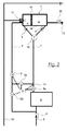
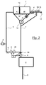
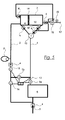
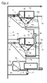
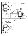
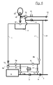
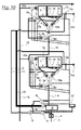
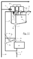
- Fig.1 to Fig.12 schematic representations of each different embodiments of the system according to the invention.
- FIG.1 a schematic representation of a first system according to the invention is shown.
- the system comprises a feed 3 having a central hot water storage / water heater 6, the central hot water storage / water heater 6 with the container 7 connecting first line section 1 and the cold water reservoir K, or the inlet between Thermoweiche 10 and cold water reservoir K, the container 7 with the The second line section 2 should be connectable both with the inlet, as well as with the first line section 1 near the hot water storage / water heater 6.
- the hot water withdrawal takes place via a hot water tapping point 12.
- Cold water chamber K and hot water chamber W are not pressure-insulated by a piston 14, but thermally insulated from each other.
- an expansion vessel 9 stores a buffer amount of cold water, which freely toward the cold water chamber can flow. With the onset of hot water extraction thus warm water is removed from the hot water reservoir W. At the same time, water now flows from the expansion vessel 9 to the cold water chamber K and the piston 14 is moved in the direction of the hot water chamber W.
- the sampling sensor 13 detects the beginning or desired removal of hot water from the hot water storage / water heater 6.
- a valve 5a between the extraction sensor 13 and the hot water storage / water heater 6 opens, leaving the unhindered afterflow of hot water into the first pipe section 1 to.
- the Thermoweiche 10 now directs the water flowing depending on the temperature in the cold water chamber K or the hot water chamber W.
- the expansion vessel 9 now takes the previously removed amount of water again.
- the pump 8 pumps water from the second line section 2, through the now open valve 5b in the second line section 2, in the water heater 6.
- additional warm water flows through the first line section 1 in the direction of hot water chamber W.
- the set pressure should be close to the lowest occurring pressure.
- the heating element 16 on the hot water chamber W compensates for the low heat loss of the hot water chamber W even in the resting phases.
- the pump 8 can also be arranged in the first line section 1. Then, if this is sufficiently strong, with the valve 5a open and the valves 5b and 5c closed, the pressure and the amount of water in the buffer memory 9 can still be increased.
- Fig.2 a schematic representation of a second system according to the invention is shown.
- This system is different from the one in FIG. 1 shown essentially only by the provision of the buffer amount. So the amount that can be removed from the hot water chamber W, before the valve 5a between hot water storage / water heater 6 and sampling sensor 13, controlled by this, opens.
- the buffer quantity valve 17 Up to a volume / path set at the buffer quantity valve 17, the required amount of water is taken from the cold water line 18. When this set volume has been removed, the buffer quantity valve 17 closes and the removal sensor 13 again determines a hot water withdrawal.
- the valve 5a opens in the first line section 1 and hot water can enter the hot water chamber W from the hot water storage / water heater 6 via the first line section 1 and the thermal barrier 10.
- the leadership of the warm water through the hot water chamber to the sampling point 12 leads by mixing with the remaining warm water in the hot water chamber W to a more uniform temperature of the removed warm water, as well as in FIG. 1 ,
- the previously high-flowed cold water of the first line section 1 was passed through the thermowork 10 in the cold water chamber K. Again, starts a set period of time after removal end the pump 8 and pumps via the simultaneously open valve 5 b in the second line section 2 water from the cold water chamber K via the second line section 2 in the hot water storage / water heater 6.
- additional warm water passes through the first Line section 1 in the hot water chamber W. This additional amount should correspond to the amount of buffer plus the amount of the first wave of cooled warm water.
- valve 5c opens in the connecting line between the first line section 1 and the second line section 2 and the other two valves 5 close.
- the warm water present in the first line section 1 is thereby conveyed via the thermal barrier 10 into the hot water chamber W.
- the starting position is reached again:
- the cold water chamber K is preferably empty and the hot water chamber W filled. There is only cold water in the pipes.
- Pressure reducer 15 and heating element 16 have the same function as in FIG. 1 ,
- On valve 5a can be completely dispensed with if the check valves 4 between thermo chamber 10 and both the cold water chamber K, and the hot water chamber W open heavier than buffer flow valve 17, the pressure in the cold water pipe 18 is at least as high as in the first line section 1 and the Sensor 13 is designed for this purpose.
- FIG 3 a schematic representation of a third system according to the invention is shown.
- This system comprises a feed 3 having hot water storage / water heater 6, a this first line section 1 connecting to the container 7 and the second line section 2 connecting the cold water reservoir K, or the inlet between thermowire 10 and cold water reservoir K, of the container 7 to the first line section 1, as close as possible to the water storage / water heating device 6.
- the separation device 14 which also here as possible thermally, but does not act isolated pressure is moved from the cold water chamber K in the direction of hot water chamber W.
- the water thus required to fill the cold water chamber K is initially taken back to the buffer memory 9.
- the water in the hot water chamber W is warmer than the warm water of the hot water storage / water heater 6.
- the heating element 16 provides the necessary temperature maintenance / increase.
- the thermal mixer 19 provides for the achievement of the desired temperature by the admixture of water from the first line section 1, which is connected to its cold water inlet. Since the valve 20 is opened, the water from the buffer memory 9 can also flow via the first line section 1 to the thermal mixer 19. If the amount of buffer is consumed, then the removal sensor 13 determines the further removal.
- the valve 5 opens and the valve 20 closes.
- Warm water can now flow from the hot water storage / water heater 6 through the first line section 1 high.
- the cold water previously located in the first line section 1 is conducted to the thermo body 10 in the cold water chamber K and also used by the thermal mixer 19 for temperature reduction. Now, if the warm water passes through the actual cold water inlet of the thermal mixer 19 to this, this can close its hot water inlet, which is supplied by the hot water chamber W, completely. It ensures a constant hot water flow at the hot water tap 12.
- the buffer memory 9 is sometime, while the valve 5 is opened in the first line section 1, again filled with cold water.
- an expansion vessel is used as the buffer 9, it automatically fills on occasion to establish a pressure balance.
- a set period of time after the removal end starts the pump 8, while the valve 20 opens and closes the valve 5 in the first line section 1 at the same time.
- the warm water present in the first line section 1 is conducted via the thermal barrier 10 into the hot water chamber W.
- the starting position is reached again:
- the cold water chamber K is empty, the hot water chamber W filled, the buffer tank 9 is again filled with cold water and in the lines is only cold water.
- the hot water chamber W Due to the higher hot water temperature in the hot water chamber W, in relation only withdrawal temperature at the hot water outlet 12, which should correspond to the set desired temperature of the thermal mixer 19, the hot water chamber W less hot water is removed as the hot water tapping point 12. With this additional hot water amount in the hot water chamber W can the cooling of the first surge of the high water flowing in the first line section 1 can be compensated for. An additional amount of hot water is not necessary. A temperature increase corresponding to the local conditions must be carried out.
- the heating element 16 should be so strong that this temperature increase can be completed quickly.
- the use of a pressure reducer 15 is also here, as in the FIGS. 1 and 2 described, advantageous to damp pressure fluctuations. Due to the higher temperature in the hot water chamber W, the Thermoweiche 10 can be set to a lower switching temperature, so that not much heat energy that is still present in the not very cold water when circulating, is lost. Due to the previously existing large amount of hotter water in the hot water chamber W, the temperature still does not drop the desired temperature at the extraction point 12.
- the heating element 16 should be designed strong enough to quickly ensure a higher water temperature again.
- FIG. 4 a schematic representation of a fourth system according to the invention is shown.
- the amount of buffer as in FIG. 2 , not taken from a buffer storage, but controlled by the buffer flow valve 17 of the connected to the cold water chamber K cold water pipe 18.
- the thermal mixer 19 is supplied at the cold water inlet of two terminals.
- the cold water of the cold water chamber K is first used to lower the temperature of the warm water from the hot water chamber W somewhat to the desired temperature. This has the advantage that an evt. Over a long time caused by waste heat of the hot water chamber W in the cold water chamber K in energy transfer in the form of water heating in the cold water chamber K can still be used.
- the sensor 13 and valve 5a opens. If the hot water column via the first line section 1 arrived at the Thermoweiche 10 so that it switches, the warm water from the central hot water storage / water heater 6 can go directly to the hot water tapping point 12 over the cold water inlet of the thermal mixer 19 in the further course of removal, as this hot water temperature should correspond to the set temperature of the mixer 19.
- the pump 8 After the removal end, the pump 8, with the valve 5a open, starts for a set time and pumps additional hot water into the first line section 1 in order to compensate for the buffer quantity and the previously warm water cooled in the first wave. Also this system can be adjusted so that with only small removal over the amount of buffer addition, more additional warm water is pumped into the first line section 1, since the cooling of the first surge warm water at very low removal may need to be almost doubled. It may be necessary to add both, the "chilling noise" plus its compensation amount. This compensation depends inter alia on the temperature in the hot water chamber W, the cable length, the ambient temperature and the setting of the thermowitch 10.
- this system can also be adjusted so that even during the removal of the additional warm water is pumped into the first line section.
- the hot water column is thus faster to Thermoweiche 10 and it is less hot water from the hot water chamber W needed. Possibly.
- the amount of buffer may be higher, or the hot water chamber may be smaller or the hot water temperature may be lower.
- valve 5a closes before and valve 5b opens, and the pump 8 pumps the cold contained in the second line section 2 Water in the first line section 1, the warm water of the first line section 1 on the thermowar 10 into the hot water chamber W, and the cold water of the cold water chamber K in the second line section second
- On valve 5a can be completely dispensed with if the check valves 4 between thermo chamber 10 and both the cold water chamber K, and the hot water chamber W open heavier than buffer flow valve 17, the pressure in the cold water pipe 18 is at least as high as in the first line section 1 and the Sensor 13 is designed for this purpose.
- FIG. 5 a schematic representation of a fifth system according to the invention is shown.
- the structure corresponds essentially to the structure in FIG. 4 but the amount of buffer is like in the FIGS. 1 and 3 taken from a buffer memory 9.
- the temperature in the hot water chamber W should again be higher than the desired hot water temperature at the hot water tapping point 12, which is to correspond to the set temperature at the central hot water storage / water heater 6 and the thermal mixer 19.
- By supplying the thermal mixer 19 with water from the cold water chamber K is also how to FIG. 4 described, possibly an actually unintentional increase in temperature of the water of the cold water chamber K, caused by energy transfer from the hot water chamber W to the cold water chamber K, with used. This reduces the total energy loss.
- the temperature increase in the hot water chamber W must again be selected only so high that the cooling of the first wave of high-flowing in the first line section 1 warm water can be compensated can.
- the size of the hot water chamber W must also be chosen to match the amount of buffer and the size of the first line section 1, taking into account the hot water temperatures and the extent of cooling of the above-mentioned first surge warm water.
- the replenishment with additional warm water to compensate for the cooling of the first surge of warm water is, as described in other figures, performed by opening valve 5c and 5a and the pump 8; the filling of the first line section 1 by the pump 8 and the valves 5a and 5b.
- FIG 6 a schematic representation of a sixth system according to the invention is shown.
- two containers 7a, 7b with the associated hot water tapping points 12 are arranged in series.
- more containers are arranged in series.
- sampling sensors 13 are here also sampling sensors 13, electric valves 5 and possibly also temperature sensor 24 in the respective containers 7a, 7b arranged.
- the corresponding signals can also be transmitted, for example, via the normal mains supply of the house, so that subsequent installation in an existing building is possible without any problems. This in particular by the property that the anyway existing cold water pipe 18 is used simultaneously as a second line section 2, or can be.
- a signal transmission is also possible by inaudible, non-irritating tones over the water supply network.
- the buffer quantities are taken over buffer quantity valves 17 of the cold water line 18.
- the check valves 4 between the Thermoweiche 10 and the containers 7a, 7b should be heavier than the buffer quantity valve 17, so that the cold water chamber K is actually supplied only with cold water from the cold water pipe 18 until reaching the buffer amount. After reaching the respective amount of buffer then, initially cold, water is removed from the first line section 1.
- Per container 7a, 7b, two sensors 13 are arranged in this embodiment, one at the inlet of the first line section 1 and one at the output to the hot water tapping point 12.
- a valve known which opens only at negative pressure on the output side, but not at overpressure on the input side.
- Such a negative pressure valve 21 is arranged at the outlet of the first line section 1 of the hot water chamber W of the container 7a. If water is withdrawn from the first line section 1b via container 7b, it is in turn supplied with warm water from the hot water chamber W of the container 7a.
- container 7b can be made smaller, since only cold water from the part 1 b of the first Line section 1 flows into the cold water chamber, ie the first line section 1 between the two containers 7a, 7b. Due to the arrangement of the sensors 13, the electronic controller 22 can determine whether hot water is removed from which of the containers 7a, 7b beyond the buffer quantities and when the removal is completed.
- the hot water chambers W of the containers 7 a, 7 b can be filled again with warm water from the first line section 1. If, for example, the sensors 13c and 13d were activated in the case of container 7b, but no sensor in the case of container 7a, a desired time after the removal end would activate the pump 8 and open the valves 5a, 5e and 5d. A required additional amount of warm water would be conveyed from the central hot water storage / water heater 6 via the first line section 1 towards the hot water chamber of the container 7b.
- the Thermoweiche 10 passes incoming cold water into the cold water chamber K and possibly incoming warm water in the hot water chamber W.
- the thermal separator 14, which separates the cold water chamber K and the hot water chamber W not isolated pressure migrates towards cold water chamber K when warm water in the Hot water chamber W flows.
- Cold water from the cold water chamber K flows through valve 5d, the second line section 2, through the pump 8, closing the circuit, in the central hot water storage / water heater 6. This amount should be large enough, the amount of buffer at the sampling start and the cooling of the first surge of high through the first line section 1 flowing warm water.
- the valves 5 then close all again and the pump 8 stops. A desired time after this operation and the end of the removal, the pump 8 starts again and the valves 5b, 5e and 5d are opened.
- Hot water contained therein is passed through the thermal barrier 10 of the container 7b in its hot water chamber W.
- Cold water passes, as before, into the cold water chamber K, or from this into the second line section 2.
- the pump 8 stops and the valves 5 close.
- the hot water chamber W of the container 7b is filled again and is in the first line section 1, as in the starting position, only cold water.
- tank 7a is first filled with warm water into the hot water chamber W by starting the pump 8 and opening the valves 5a and 5c.
- the valve 5c closes and the valve 5d and 5e open.
- container 7b is filled with warm water, or additional warm water is conveyed into the first line section 1 in the direction of container 7b.
- the total amount of additional hot water is controlled by the circuit, adapted to the increased demand of two buffer quantities and the cooling of the first surge of warm water for the entire first line section 1.
- the warm water is conveyed from the first pipe section 1 into the hot water chamber W.
- Container 7a was previously completely filled with warm water.
- the pump 8 remains activated and the valves 5b, 5e and 5d open.
- Cold water from the first line section 1 is possibly again on the thermal well 10 and the cold water chamber K of the container 7b is conveyed into the second conduit section 2; warm water according to the hot water chamber W, which then again conveys the cold water from the cold water chamber K in the second line section 2.
- warm water according to the hot water chamber W which then again conveys the cold water from the cold water chamber K in the second line section 2.
- a cold water removal via the cold water pipe 18 while the pump 8 operates only has an influence on the flow direction and speed of cold water in the cold water pipe 18, if this is also used as the second line section 2, but does not affect the operation principle and the mode of operation of the system.
- FIG 7 a schematic representation of a seventh system according to the invention is shown.
- two containers 7 with the associated hot water tapping points 12 and a hot water tapping point 12 arranged close to the central hot water supply / hot water heating device 6 without a container 7 are distinguished from the others Figures 1-5 and 8th
- sampling sensors 13 electric valves 5 and possibly also temperature sensor 24 are arranged at the respective containers 7.
- the corresponding signals can also be transmitted, for example, via the normal mains supply of the house, so that subsequent installation in an already existing house is possible without any problems.
- the buffer amounts are again taken over buffer quantity valves 17 of the cold water line 18.
- the check valves 4 between Thermoweiche 10 and container 7 should be heavier than the buffer quantity valve 17, so that the cold water chamber K is actually supplied only with cold water from the cold water pipe 18 until reaching the buffer amount.
- cold water is removed from the first line section 1.
- the corresponding sensors will respond. For example, if warm water has been taken from tank 7a beyond the amount of buffer, sensors 13a and 13c will respond. For container 7b sensors 13b and 13c. If only sensor 13c is activated, then the controller recognizes a removal of water from a hot water tapping point 12 without containers 7a, 7b. For example, if hot water has been removed from tank 7a beyond the amount of the buffer, it will be supplied with additional warm water necessary to replace the amount of buffer and first swirl of cooled warm water by opening valves 5a and 5c and activating the pump ,
- the controller can already do this during hot water extraction, or after its end.
- a set time after the end of the hot water withdrawal from container 7a, the controller activates the pump 8 again, this time together with the valves 5b and 5c.
- the warm water in the first line section 1 is conveyed by the thermal barrier 10 into the hot water chamber W of the container 7 a and replaced by cold water from the second line section 2.
- This circulation phase which also lasts only a short time, can be subdivided by the control into a plurality of even shorter phases, in order to prevent any removal at the removal point 12 without containers 7 and not disturb.
- the controller would interrupt this phase and continue a little later. Also, it would interrupt this phase, for example, if during this time sensor 13b would respond. If both containers 7a, 7b were activated in rapid succession, the controller should first carry out the circulation phase of the container whose buffer quantity was first exceeded. Namely, the other container 7b had to compensate only parts of the first line section 1, from the branch of the first line section 1 to the container 7b.
- this system can according to the Fig. 3 . 4 . 5 and 8th changed, the temperature in the hot water chambers W are selected higher and mixed by a mixer back to the desired temperature level. According to the FIGS. 4 and 5 It would thus be possible to minimize any energy loss that may be present due to energy transfer from the hot water chamber W into the cold water chamber K.
- the desired temperatures of the hot water chambers W can be set and changed by the control unit 22. Regardless of whether it is centrally or decentrally controlled, the heating elements 16 can operate active legionella protection by deliberately heating up the water in the hot water chamber W.
- This system can be operated in almost all houses, whether in new buildings or as retrofitting into existing buildings. It does not rely on separate circulation lines and is compatible with hot water taps 12 on arranged container 7. Even the signals for the valves and sensors could without separate electrical line through the building's power network or even as inaudible sound wave signals via the water lines to and from the control unit 22 be transmitted.
- FIG 8 is a schematic representation of an eighth system according to the invention shown.
- the container 23 which should be thermally insulated, but no cold water chamber, but has a hot water chamber W and a gas chamber, which are not isolated from each other pressure.
- the pressure in the system is not constant, so a pressure reducer 15 should be used. This should be set to about the lowest occurring system pressure.
- the thermal mixer 19 with connection to the cold water pipe 18 is not necessary, but supports a use of heat energy in transition phases from cold to warm at the first surge of high-flow water.
- the temperature of the heated by the heating element 16 and kept warm warm water in the container 23 can be set higher and thus this container can be made smaller or allow a correspondingly higher amount of buffer.
- the thermal mixer 19 initially uses the hot water chamber W and possibly from the cold water pipe 18 to produce the desired water temperature. If a certain amount of warm water has been removed from the hot water chamber W and thus a correspondingly lower pressure has been reached, which should also be below the pressure of the cold water line 18, a pressure sensor 13 detects this.
- the valves 5b, 5c, 5d and 5e open and at the same time the pump 8 starts. Thereby, cold water is conveyed from the first line section 1 into the second line section 2, the water from the second line section 2 into the central hot water storage / water heater 6 and from there warm water in the first line section 1.
- the pump covers additional water demand with water from the supply line 3 via valve 5d Since it should be a strong pump, the warm water is transported quickly and with high pressure to Thermoweiche 10. Due to the higher pressure in the first line section 1 than in the cold water line 18, the thermal mixer 19 is supplied at its cold water inlet with water from the first line section 1. This further speeds up the flow of warm water to the thermal mixer 19.
- the pump 8 stops and the valves 5b, 5c and 5d close. It can continue to be removed hot water, but which flows through the cold water inlet of the thermal mixer 19 and thus prevents further removal of possibly even warmer water from the hot water chamber W. This at least when the flowing after warm water reaches the set temperature of the thermal mixer 19.
- the container 23 may also take on warm water until a pressure equilibrium prevails. A set time after removal, even before the standing in the first line section 1 warm water is cooled too much, the pump starts again.
- thermo-mixer 19 can be operated with thermo-mixer 19, even without thermo-fuse 10, with a correspondingly accurate setting or possibly lower requirements for accuracy.
- FIG. 9 a schematic representation of a ninth system according to the invention is shown.
- the size of the containers 7a, 7b is oriented only according to the line contents of the line section 1 in front of the respective container 7a, 7b to the next active container 7a, 7b and the desired amount of buffer.
- the containers 7a, 7b are not all connected to the second line section 2, but only the last container of the series.
- the second line section 2 does not simultaneously serve as a cold water line 18. It is therefore particularly advantageous that the second line section does not have to be guided / routed everywhere where containers 7a, 7b are arranged.
- a separate line section 2, referred to in practice circulation line, in particular, if applicable, meets existing strict regulations on the arrangement and use of cold water pipes. This is especially true for public or large facilities, such as hotels.
- the heating elements 16 of individual containers 7a, 7b are deactivated when the container size of the subsequent container in the row 7a, 7b is sufficiently large and is controlled accordingly. For example, with longer vacancies of hotel rooms even more energy can be saved, since the affected heating elements 16 consume no electricity.
- the heating element 16 starts to heat again, so that immediately hot water at the sampling point 12 is available. Alternatively, you can just run away the now chilled water.
- the hot water chamber is then filled with warm water again. In another arrangement, it is also possible to have this process take place automatically when the container 7a, 7b is reactivated.
- the hot water chamber W would only have to be connected to a water drain and then let a valve through an appropriate amount of water in the drain.
- FIG. 9 The operation of an arrangement gem.
- FIG. 9 is as follows: If hot water is withdrawn via extraction point 12b from the filled hot water chamber W of container 7b, the piston travels 14. The cold water chamber takes cold water from the cold water line 18, since the valve 20b is opened. As soon as the level sensor 31 responds because the amount of buffer has been used up, valve 20b closes and valve 5d opens.
- the level sensors 31 may be, for example, magnetic field sensors or reed switches, which detect the position of the piston via a built-in this magnet.
- the level can be changed and adapted at any time by means of the electronic connection of the control unit 22. This can also be done automatically, for example, if the upstream container 7a is deactivated. In addition, the system itself can be designed to be learning.
- valve 5d opens because of hot water demand in container 7b, so also opens the same time valve 5e.
- warm water can flow from the hot water chamber W from the tank 7a via the first pipe section 1b to the tank 7b.
- the initially cold water from the first line section 1 b is passed from the thermowork 10 b in the cold water chamber K of container 7 b.
- the workflow in container 7a is corresponding.
- the cold water from the cold water chamber K is brought from container 7b in the second line section and the warm water in the first line section 1 b on the Thermoweiche 10b in the hot water chamber W of the container 7b. Possibly. cold water still flowing out of the line section 1 also flows via the cold water chamber K of the container 7b into the second line section 2. After this short pumping operation the pump 8 stops and all the valves return to their idle state.
- the valve 20a closes here and the valve 5c opens.
- the buffer limit must be designed and adjusted for all containers 7a, 7b so that warm water reaches the container via line section 1 before its hot water chamber W is empty. Since the tank 7a is the first of the tanks 7a, 7b arranged in series, it is supplied with warm water via the first pipe section 1a directly from the central hot water tank. This phase of the workflow now offers the possibility to completely fill the hot water chamber W of the container 7a again with warm water. After a set waiting time after removal end from the sampling point 12a, the pump 8 starts again and the valves 5i, 5f and 5b open. Valve 5c is still open.
- the hot water chamber W of the tank 7a is filled with warm water
- the cold water of the cold water chamber K of the tank 7a flows through the valve 5f, the first pipe section 1b, the valve 5b and the second pipe section 2 toward the pump 8.
- Valve 5i is switched off and valve 5j is activated.
- the pump 8 now carries cold water from the second line section 2 in the first line section 1 a and thus pushes the remaining warm water in the container 7 a. If there is no longer any warm water in the first line section 1 a, the pump 8 stops and all valves return to their idle state.
- a special type of hot water replenishment is the following "refill circulation", especially for multi-tank installations 7a, 7b: With this type of replenishment, all of the tanks 7a, 7b in the row can be up to the farthest tank 7b, which is sufficiently deflated during filling again with warm water.
- the container 7b is the last container of the row to be filled.
- valve 5a can additionally be opened for this process as soon as warm water is still present in all affected parts of the first line section 1. This would reduce the flow resistance considerably, since the valve 5a should preferably be designed as a valve with full pipe passage.
- the valve 5a instead of 5c and 5e, immediately open when the container 7a is sufficiently emptied and on the container 7b no removal takes place. This process is carried out until the container 7b can receive only the simple amount of hot water from the first line section 1b. Its level sensor detects this. Now close the valve 5e and 5a and the valve 5f opens; Valve 5c is still open.
- the warm water from the first line section 1 b is replaced by cold water and the hot water chamber W of the container 7 b ideally filled completely with warm water.
- Container 7a is further filled with warm water until it has reached the appropriate level.
- valve 5i closes and valve 5j opens.
- the warm water flows from the first line section 1 a in the container 7 a and the line is filled with cold water.
- the pump stops 8 and all valves return to the idle state.
- the container 7a, 7b can be used quite normal and unnoticed for hot water supply.
- the system acc. Figure 9 is particularly suitable for systems that are used at times extremely strong and at times very little or not at all, and need many containers 7 arranged in series. Hotels are an example of this. If the system detects a very strong use, it can be switched to a hot water circulation system, in which then flows through both pipe sections 1 and 2 with warm water. This can prevent unnecessary frequent work and switching of the system.
- Such a circulation process can also be used to flush out the lines regularly for reasons of water hygiene. At the same time, this process can be used to fill the containers 7a, 7b as described above.
- this structure of a system according to the invention can be designed so that there is more than one connection between containers 7 and the second line section 2, analogous to FIG. 6 , This makes it even easier to disable large parts of the system and simplify the workflow if necessary.
- An inventive system acc. Figure 9 does not necessarily have to be arranged as a single row. Branching or even multi-branching arrangements are also no problem for such a system. The branches can even be merged again and thus use a common last container 7b or only at the respective last container 7b a common line section 2.
- pressure reducers at the tapping points 12 is advantageous, since thus strong pumps 8 can be used and the hot water pressure at the tapping points 12 is always uniform. Furthermore, the use of thermo mixers with simultaneously elevated temperature in the hot water chambers W of the container 7a, 7b is advantageous. Legionella can be particularly well avoided or even combated. And the filling of the first line section 1 following the container 7a is then particularly effective.
- FIG. 10 a schematic representation of a tenth system according to the invention is shown.
- a hot water pipe 30 is arranged. This also leads along there, where the containers 7 are arranged.
- this hot water pipe 30 is only used for hot water, if at times particularly high hot water demand at many tapping points 12. For example, at peak times and full occupancy in large hotel complexes.
- the hot water pipe 30 uses the second pipe section 2 as the circulation pipe 11.
- the remaining system which corresponds to the in FIG. 9 corresponds, then can also, how to FIG. 9 explained to be used as a circulation system. This again increases the maximum possible hot water flow at the sampling points. Alternatively, it can also be switched off during use of the hot water pipe 30.
- FIG. 10 The advantage of a plant gem.
- FIG. 10 is that the first line sections 1 need not be designed for a particularly strong hot water demand and thus can have a small diameter. As a result, the containers 7 can again be made smaller.
- the warm water after use of the hot water pipe 30 in this should also be replaced by cold water.
- a suitable device for catching and temporarily storing the warm water should be installed in case that warm water is not consumed by the normal use in a short time.
- the system can be modified by small changes so as to dispense with a separate circulation line 11. If the system according to the invention operates, then the hot water line is used as line section 2. Activated in times of very high hot water demand but the hot water pipe 30 as actually circulating hot water supply, the line section 1 of the hot water pipe 30 can serve as a circulation line.
- FIG. 11 a schematic representation of an eleventh system according to the invention is shown.
- the amount of buffer such as in FIG. 2
- the buffer quantity valve 17 leaves above the buffer limit no more water in the cold water chamber K.
- the cold water chamber K, the transitional water chamber ÜW and the hot water chamber W together form the container 7. Again, they are thermally insulated from each other, but are on the air / gas lines 32 in a pressure balance.
- Thermowood 10 has three outputs here, one for cold, one not quite warm and one for warm water.
- the removal sensor 13 here designed as a pressure sensor for example, determines the hot water supply.
- the electric control opens valve 5c.
- the water in the first line section 1 at this time is cold.
- this is passed to the Thermoweiche 10 in the cold water chamber K, the only slightly warm water in the transitional water chamber ÜW and the sufficiently warm water in the hot water chamber W.
- the water temperature in the hot water chamber W is heated by the heating element 16 to above the desired temperature at the extraction point 12.
- the thermal mixer 19 mixes it down to the desired temperature.
- thermowire 10 When the thermowire 10 transmits the sufficiently warm water in the direction of the hot water chamber, it is also preferably used at the thermal mixer 19, but at its cold water inlet. Since this after flowing warm water already set at the thermal mixer 19 and at the removal point 12 desired temperature, now only this warm water is used. The remaining transitional water in the transitional water chamber ÜW is now also heated by means of a heating element 16, but only to the desired temperature at the removal point 12. Thus, there is a lot of warm water available for the next extraction, the buffer limit is not reached so quickly and the system is activated later or less frequently.
- the heater 16 at the transitional water chamber ÜW its transitional water can be brought by appropriate arrangement of the hot water chamber W by the waste heat to the desired temperature. If no warm water is removed for a certain time, the pump 8 starts and additionally conveys some warm water through the opened valves 5a and 5b into the first line section 1. This is intended to ensure the buffer quantity for the next hot water withdrawal and to compensate for other possible losses. Thereafter, valve 5b is closed and valve 5c is opened. The still in the first line section 1 located warm water flows into the hot water chamber W, followed by a renewed transitional amount of water, which is passed into the transitional water chamber ÜW. All pipe sections are cold again and the hot water chamber W filled sufficiently for the next removal.
- container 7 are also all previously or elsewhere mentioned container 7 with membrane or piston.
- container 7 with membrane or piston are also all previously or elsewhere mentioned container 7 with membrane or piston.
- FIG 12 a schematic representation of a twelfth system according to the invention is shown.
- a heat exchanger 33 is mounted instead of a normal transitional water chamber.
- this heat exchanger 33 is not a countercurrent heat exchanger. Instead, both liquids move in the same direction next to each other in two different chambers. For example, in normal countercurrent heat exchanges, one can swap the connections for one of the two liquids. The output becomes the input and vice versa. The meaning of this arrangement is explained by the way the system works.
- the cold water from the first line section 1 is first passed into the cold water chamber K. As soon as a little warmer water reaches the thermowood, it switches over and directs this transitional water towards the thermal mixer 19 and the heat exchanger 33.
- the thermo mixer 19 now uses more and more of it with the transition water temperature to increase the hot water to be used through the heat exchanger from the Hot water chamber W after flows to bring to the desired temperature of the sampling point 12.
- thermomixer 19th This afterflow comes to a standstill and the warm water flows only through the cold water inlet of the thermo mixer 19 to the sampling point 12. This also gets no, cooled by the presence of transitional water in the heat exchanger, cooled water to the hot water inlet of the thermomixer 19th
- the heating element now has time to heat the two quantities of liquid, which are now in the heat exchanger 33, to the temperature level of the hot water chamber W.
- Heat exchanger 33 and heating element 16 may for example be mounted so that a heating element 16 both the heat exchanger 33 and the hot water chamber W is heated, or permanently maintained at the desired temperature of the hot water chamber.
- the size of the heat exchanger 33 is preferably chosen at least so large that each of the two chambers can accommodate at least the simple incoming transitional water quantity.
- valve 5a the pump 8 starts and in addition to valve 5a also opens valve 5b.
- cold water is drawn out of the cold water chamber K and warm water is conveyed in the direction of the hot water chamber W.
- This amount of hot water is especially the warm amount of buffer for the next removal and compensates possibly known smaller hot water losses of a working cycle.
- valve 5b closes and valve 5c opens. It is still drawn cold water from the cold water chamber K. This is now pumped directly into the first line section 1 and thus pushes the warm water contained therein further into the hot water chamber W.
- the transitional water following the warm water also flows in the direction of the heat exchanger or hot water chambers W. If the transitional water has also passed through the thermal barrier 10, it switches over and directs the now cold water into the cold water chamber K and from there into the second line section 2. Pump 8 now stops and all valves 5 close.
- the heater 16 heats the water in the heat exchanger and hot water chamber to the desired temperature of the hot water chamber W. The starting position is reached again.
- the cold water chamber K is (nearly) empty, the hot water chamber W and the heat exchanger 33 are filled with hot water and the line sections all with cold water.
- the check valves at the outputs of the cold water chamber K and the hot water chamber W to the thermal mixer 19 open slightly heavier, so that the hot water flowing directly from the first line section 1 is preferably used at the cold water inlet of the thermal mixer 19.
- the cold and hot water chamber also form the container 7 here.
- This embodiment of the hot and cold water chambers W and K as a container 7 in combination with the affiliated valves 4 and 17, the heat exchanger 33 and the thermal mixer 19 are also applicable to other listed embodiments of the system according to the invention, if necessary to include additional valves 5 incl. electrical connection to the control unit 22 supplements possible.
- the cold and hot water chamber K and W are thermally separated from each other by air or gas. But other designs such as piston or membrane containers can store cold and hot water separately.
- the system according to the invention is not limited in its execution to the above-mentioned preferred embodiments. Rather, a variety of design variations are possible, which make use of the solution shown even with fundamentally different type of execution. Also, the illustrated solution may also be used to economically provide cold water, or other cold or hot liquid. The components and the operation of the system must then be used mutatis mutandis and modified if necessary.
Landscapes
- Engineering & Computer Science (AREA)
- Physics & Mathematics (AREA)
- Thermal Sciences (AREA)
- Chemical & Material Sciences (AREA)
- Combustion & Propulsion (AREA)
- Mechanical Engineering (AREA)
- General Engineering & Computer Science (AREA)
- Heat-Pump Type And Storage Water Heaters (AREA)
- Domestic Hot-Water Supply Systems And Details Of Heating Systems (AREA)
Applications Claiming Priority (2)
| Application Number | Priority Date | Filing Date | Title |
|---|---|---|---|
| DE102011014527A DE102011014527A1 (de) | 2011-03-18 | 2011-03-18 | System zur Bereitstellung erwärmten Brauchwassers in einem Leitungssystem |
| DE102012101436 | 2012-02-23 |
Publications (3)
| Publication Number | Publication Date |
|---|---|
| EP2503252A2 true EP2503252A2 (fr) | 2012-09-26 |
| EP2503252A3 EP2503252A3 (fr) | 2016-08-10 |
| EP2503252B1 EP2503252B1 (fr) | 2020-04-29 |
Family
ID=45936792
Family Applications (1)
| Application Number | Title | Priority Date | Filing Date |
|---|---|---|---|
| EP12159873.4A Active EP2503252B1 (fr) | 2011-03-18 | 2012-03-16 | Système de préparation d'eau chaude non potable dans un système de conduites |
Country Status (1)
| Country | Link |
|---|---|
| EP (1) | EP2503252B1 (fr) |
Cited By (7)
| Publication number | Priority date | Publication date | Assignee | Title |
|---|---|---|---|---|
| FR3004791A1 (fr) * | 2013-04-19 | 2014-10-24 | Geocal | Procede de regulation d'eau chaude sanitaire |
| DE102014006539A1 (de) | 2014-05-05 | 2015-11-05 | Markus Keitsch | Ein besonders leicht nachrüstbares, besonders vielseitig einsetzbares, sehr energiesparendes und einfach steuerbares System zur Bereitstellung warmen Wassers, oder anderer Medien mit einer Temperaturdifferenz zur Umgebung in einem Leitungssystem |
| DE102015001450A1 (de) | 2014-07-02 | 2016-01-07 | Markus Keitsch | System zum energiesparenden Betrieb nicht permanent genutzter oder nicht permanent ausgelasteter Wärmetauscher in einem Leitungssystem, insbesondere zur Trinkwassererwärmung |
| DE102015006945A1 (de) | 2015-06-05 | 2016-12-08 | Markus Keitsch | System zur beschleunigten Beförderung warmer Flüssigkeit in einem kälteren Leitungssystem bei spontan einsetzendem Bedarf an warmer Flüssigkeit bei dezentralen Wärmetauschern oder dezentralen Zwischenspeichern |
| US20180180298A1 (en) * | 2015-07-02 | 2018-06-28 | 3Eflow Ab | A liquid distribution unit |
| WO2020108908A1 (fr) | 2018-11-29 | 2020-06-04 | Truma Gerätetechnik GmbH & Co. KG | Dispositif de chauffage d'un liquide ainsi que procédé correspondant |
| WO2025215309A1 (fr) | 2024-04-09 | 2025-10-16 | David Perrin | Procédé et dispositif de distribution d'eau chaude sanitaire |
Families Citing this family (1)
| Publication number | Priority date | Publication date | Assignee | Title |
|---|---|---|---|---|
| FR3166425A1 (fr) * | 2024-09-18 | 2026-03-20 | Commissariat A L' Energie Atomique Et Aux Energies Alternatives | Dispositif automatisé de distribution d’eau chaude |
Family Cites Families (2)
| Publication number | Priority date | Publication date | Assignee | Title |
|---|---|---|---|---|
| DE19619566C1 (de) * | 1996-05-15 | 1997-11-27 | Solvis Solarsysteme Gmbh | Anordnung und Verfahren zur Bereitstellung von warmem Brauchwasser |
| DE10343700A1 (de) * | 2003-09-18 | 2005-05-04 | Markus Keitsch | System zur Bereitstellung von erwärmtem Brauchwasser in einem Leitungssystem und Ventil zu dessen Steuerung |
-
2012
- 2012-03-16 EP EP12159873.4A patent/EP2503252B1/fr active Active
Cited By (9)
| Publication number | Priority date | Publication date | Assignee | Title |
|---|---|---|---|---|
| FR3004791A1 (fr) * | 2013-04-19 | 2014-10-24 | Geocal | Procede de regulation d'eau chaude sanitaire |
| DE102014006539A1 (de) | 2014-05-05 | 2015-11-05 | Markus Keitsch | Ein besonders leicht nachrüstbares, besonders vielseitig einsetzbares, sehr energiesparendes und einfach steuerbares System zur Bereitstellung warmen Wassers, oder anderer Medien mit einer Temperaturdifferenz zur Umgebung in einem Leitungssystem |
| DE102015001450A1 (de) | 2014-07-02 | 2016-01-07 | Markus Keitsch | System zum energiesparenden Betrieb nicht permanent genutzter oder nicht permanent ausgelasteter Wärmetauscher in einem Leitungssystem, insbesondere zur Trinkwassererwärmung |
| DE102015006945A1 (de) | 2015-06-05 | 2016-12-08 | Markus Keitsch | System zur beschleunigten Beförderung warmer Flüssigkeit in einem kälteren Leitungssystem bei spontan einsetzendem Bedarf an warmer Flüssigkeit bei dezentralen Wärmetauschern oder dezentralen Zwischenspeichern |
| US20180180298A1 (en) * | 2015-07-02 | 2018-06-28 | 3Eflow Ab | A liquid distribution unit |
| US10801736B2 (en) * | 2015-07-02 | 2020-10-13 | 3Eflow Ab | Liquid distribution unit |
| WO2020108908A1 (fr) | 2018-11-29 | 2020-06-04 | Truma Gerätetechnik GmbH & Co. KG | Dispositif de chauffage d'un liquide ainsi que procédé correspondant |
| DE102018009377A1 (de) | 2018-11-29 | 2020-06-04 | Truma Gerätetechnik GmbH & Co. KG | Vorrichtung zum Erwärmen einer Flüssigkeit sowie entsprechendes Verfahren |
| WO2025215309A1 (fr) | 2024-04-09 | 2025-10-16 | David Perrin | Procédé et dispositif de distribution d'eau chaude sanitaire |
Also Published As
| Publication number | Publication date |
|---|---|
| EP2503252A3 (fr) | 2016-08-10 |
| EP2503252B1 (fr) | 2020-04-29 |
Similar Documents
| Publication | Publication Date | Title |
|---|---|---|
| EP2503252B1 (fr) | Système de préparation d'eau chaude non potable dans un système de conduites | |
| EP2963350B1 (fr) | Systeme destine a un fonctionnement a economie d'energie d'un echangeur thermique utilise ou exploite par intermittence dans un systeme de conduites, en particulier destine au chauffage de l'eau potable | |
| EP2966384A1 (fr) | Dispositif de refroidissement d'un débit volumique d'eau potable | |
| EP1170554B1 (fr) | Ensemble et procédé pour préparer de l'eau chaude sanitaire | |
| DE102012011042A1 (de) | Verbessertes System zur Bereitstellung von erwärmtem Wasser in einem Leitungssystem | |
| EP3705789B1 (fr) | Système d'alimentation en eau et son procédé de fonctionnement | |
| CH708598A1 (de) | Anordnung und Verfahren zum Raumtemperieren und Warmwasserbereitstellen. | |
| DE102008033063A1 (de) | Verfahren und Vorrichtung zur zentralen Warmwasserversorgung | |
| DE102011014527A1 (de) | System zur Bereitstellung erwärmten Brauchwassers in einem Leitungssystem | |
| DE10226870B4 (de) | Hausanschlussstation für Fernwärme | |
| EP1517097B1 (fr) | système pour fournir de l'eau chaude sanitaire dans un système de canalisation et soupape pour dudit commander | |
| EP2226571B1 (fr) | Agencement et procédé de chauffage d'eau potable pour un site de consommation, respectivement, de distribution | |
| EP2413047B2 (fr) | Unité de chauffage d'eau potable | |
| DE3727442A1 (de) | Verfahren zur erzeugung von warmwasser und vorrichtung zur durchfuehrung dieses verfahrens | |
| DE102018100525A1 (de) | System zur Bereitstellung von Heizwärme und warmem Trinkwasser | |
| DE102013012724B4 (de) | Vorrichtung zur Erwärmung von Heizwasser für eine Warmwasserbereitung | |
| DE112013001269B4 (de) | Verfahren zum Betrieb einer Warmwasserversorgungsanlage sowie Warmwasserversorgungsanlage zur Durchführung des Verfahrens | |
| DE102013008991A1 (de) | Effizientes, vielseitig einsetzbares, einfach steuerbares und leicht nachrüstbares System zur Bereitstellung warmen Wassers, oder anderer Medien mit einer Temperaturdifferenz zur Umgebung, in einem Leitungssystem | |
| DE102014006539A1 (de) | Ein besonders leicht nachrüstbares, besonders vielseitig einsetzbares, sehr energiesparendes und einfach steuerbares System zur Bereitstellung warmen Wassers, oder anderer Medien mit einer Temperaturdifferenz zur Umgebung in einem Leitungssystem | |
| DE102015118826A1 (de) | Anordnung und Verfahren zur Bereitstellung von warmem Trinkwasser mit einem Wärmeübertrager | |
| EP2413044B1 (fr) | Unité de chauffage d'eau potable | |
| CH655376A5 (de) | Heizanlage zur warmwasserbereitung. | |
| CH708784A2 (de) | Warmwassersystem zur Bereitstellung von Trinkwasser. | |
| DE102005007452A1 (de) | Vorrichtung zur thermischen Desinfektion von Trinkwarmwasserversorgungsanlagen | |
| DE202013007901U1 (de) | Vorrichtung zur Erwärmung von Trinkwasser für ein Verteilnetz |
Legal Events
| Date | Code | Title | Description |
|---|---|---|---|
| PUAI | Public reference made under article 153(3) epc to a published international application that has entered the european phase |
Free format text: ORIGINAL CODE: 0009012 |
|
| AK | Designated contracting states |
Kind code of ref document: A2 Designated state(s): AL AT BE BG CH CY CZ DE DK EE ES FI FR GB GR HR HU IE IS IT LI LT LU LV MC MK MT NL NO PL PT RO RS SE SI SK SM TR |
|
| AX | Request for extension of the european patent |
Extension state: BA ME |
|
| PUAL | Search report despatched |
Free format text: ORIGINAL CODE: 0009013 |
|
| AK | Designated contracting states |
Kind code of ref document: A3 Designated state(s): AL AT BE BG CH CY CZ DE DK EE ES FI FR GB GR HR HU IE IS IT LI LT LU LV MC MK MT NL NO PL PT RO RS SE SI SK SM TR |
|
| AX | Request for extension of the european patent |
Extension state: BA ME |
|
| RIC1 | Information provided on ipc code assigned before grant |
Ipc: F24D 17/00 20060101AFI20160707BHEP Ipc: F24D 19/10 20060101ALI20160707BHEP |
|
| STAA | Information on the status of an ep patent application or granted ep patent |
Free format text: STATUS: REQUEST FOR EXAMINATION WAS MADE |
|
| 17P | Request for examination filed |
Effective date: 20170130 |
|
| RBV | Designated contracting states (corrected) |
Designated state(s): AL AT BE BG CH CY CZ DE DK EE ES FI FR GB GR HR HU IE IS IT LI LT LU LV MC MK MT NL NO PL PT RO RS SE SI SK SM TR |
|
| STAA | Information on the status of an ep patent application or granted ep patent |
Free format text: STATUS: EXAMINATION IS IN PROGRESS |
|
| 17Q | First examination report despatched |
Effective date: 20171214 |
|
| GRAP | Despatch of communication of intention to grant a patent |
Free format text: ORIGINAL CODE: EPIDOSNIGR1 |
|
| STAA | Information on the status of an ep patent application or granted ep patent |
Free format text: STATUS: GRANT OF PATENT IS INTENDED |
|
| INTG | Intention to grant announced |
Effective date: 20191126 |
|
| GRAS | Grant fee paid |
Free format text: ORIGINAL CODE: EPIDOSNIGR3 |
|
| GRAA | (expected) grant |
Free format text: ORIGINAL CODE: 0009210 |
|
| STAA | Information on the status of an ep patent application or granted ep patent |
Free format text: STATUS: THE PATENT HAS BEEN GRANTED |
|
| AK | Designated contracting states |
Kind code of ref document: B1 Designated state(s): AL AT BE BG CH CY CZ DE DK EE ES FI FR GB GR HR HU IE IS IT LI LT LU LV MC MK MT NL NO PL PT RO RS SE SI SK SM TR |
|
| REG | Reference to a national code |
Ref country code: GB Ref legal event code: FG4D Free format text: NOT ENGLISH |
|
| REG | Reference to a national code |
Ref country code: CH Ref legal event code: EP |
|
| REG | Reference to a national code |
Ref country code: DE Ref legal event code: R096 Ref document number: 502012016008 Country of ref document: DE |
|
| REG | Reference to a national code |
Ref country code: AT Ref legal event code: REF Ref document number: 1263908 Country of ref document: AT Kind code of ref document: T Effective date: 20200515 |
|
| REG | Reference to a national code |
Ref country code: IE Ref legal event code: FG4D Free format text: LANGUAGE OF EP DOCUMENT: GERMAN |
|
| REG | Reference to a national code |
Ref country code: NL Ref legal event code: MP Effective date: 20200429 |
|
| REG | Reference to a national code |
Ref country code: LT Ref legal event code: MG4D |
|
| PG25 | Lapsed in a contracting state [announced via postgrant information from national office to epo] |
Ref country code: PT Free format text: LAPSE BECAUSE OF FAILURE TO SUBMIT A TRANSLATION OF THE DESCRIPTION OR TO PAY THE FEE WITHIN THE PRESCRIBED TIME-LIMIT Effective date: 20200831 Ref country code: GR Free format text: LAPSE BECAUSE OF FAILURE TO SUBMIT A TRANSLATION OF THE DESCRIPTION OR TO PAY THE FEE WITHIN THE PRESCRIBED TIME-LIMIT Effective date: 20200730 Ref country code: FI Free format text: LAPSE BECAUSE OF FAILURE TO SUBMIT A TRANSLATION OF THE DESCRIPTION OR TO PAY THE FEE WITHIN THE PRESCRIBED TIME-LIMIT Effective date: 20200429 Ref country code: NO Free format text: LAPSE BECAUSE OF FAILURE TO SUBMIT A TRANSLATION OF THE DESCRIPTION OR TO PAY THE FEE WITHIN THE PRESCRIBED TIME-LIMIT Effective date: 20200729 Ref country code: SE Free format text: LAPSE BECAUSE OF FAILURE TO SUBMIT A TRANSLATION OF THE DESCRIPTION OR TO PAY THE FEE WITHIN THE PRESCRIBED TIME-LIMIT Effective date: 20200429 Ref country code: IS Free format text: LAPSE BECAUSE OF FAILURE TO SUBMIT A TRANSLATION OF THE DESCRIPTION OR TO PAY THE FEE WITHIN THE PRESCRIBED TIME-LIMIT Effective date: 20200829 Ref country code: LT Free format text: LAPSE BECAUSE OF FAILURE TO SUBMIT A TRANSLATION OF THE DESCRIPTION OR TO PAY THE FEE WITHIN THE PRESCRIBED TIME-LIMIT Effective date: 20200429 |
|
| PG25 | Lapsed in a contracting state [announced via postgrant information from national office to epo] |
Ref country code: BG Free format text: LAPSE BECAUSE OF FAILURE TO SUBMIT A TRANSLATION OF THE DESCRIPTION OR TO PAY THE FEE WITHIN THE PRESCRIBED TIME-LIMIT Effective date: 20200729 Ref country code: LV Free format text: LAPSE BECAUSE OF FAILURE TO SUBMIT A TRANSLATION OF THE DESCRIPTION OR TO PAY THE FEE WITHIN THE PRESCRIBED TIME-LIMIT Effective date: 20200429 Ref country code: RS Free format text: LAPSE BECAUSE OF FAILURE TO SUBMIT A TRANSLATION OF THE DESCRIPTION OR TO PAY THE FEE WITHIN THE PRESCRIBED TIME-LIMIT Effective date: 20200429 Ref country code: HR Free format text: LAPSE BECAUSE OF FAILURE TO SUBMIT A TRANSLATION OF THE DESCRIPTION OR TO PAY THE FEE WITHIN THE PRESCRIBED TIME-LIMIT Effective date: 20200429 |
|
| PG25 | Lapsed in a contracting state [announced via postgrant information from national office to epo] |
Ref country code: NL Free format text: LAPSE BECAUSE OF FAILURE TO SUBMIT A TRANSLATION OF THE DESCRIPTION OR TO PAY THE FEE WITHIN THE PRESCRIBED TIME-LIMIT Effective date: 20200429 Ref country code: AL Free format text: LAPSE BECAUSE OF FAILURE TO SUBMIT A TRANSLATION OF THE DESCRIPTION OR TO PAY THE FEE WITHIN THE PRESCRIBED TIME-LIMIT Effective date: 20200429 |
|
| PG25 | Lapsed in a contracting state [announced via postgrant information from national office to epo] |
Ref country code: DK Free format text: LAPSE BECAUSE OF FAILURE TO SUBMIT A TRANSLATION OF THE DESCRIPTION OR TO PAY THE FEE WITHIN THE PRESCRIBED TIME-LIMIT Effective date: 20200429 Ref country code: SM Free format text: LAPSE BECAUSE OF FAILURE TO SUBMIT A TRANSLATION OF THE DESCRIPTION OR TO PAY THE FEE WITHIN THE PRESCRIBED TIME-LIMIT Effective date: 20200429 Ref country code: EE Free format text: LAPSE BECAUSE OF FAILURE TO SUBMIT A TRANSLATION OF THE DESCRIPTION OR TO PAY THE FEE WITHIN THE PRESCRIBED TIME-LIMIT Effective date: 20200429 Ref country code: IT Free format text: LAPSE BECAUSE OF FAILURE TO SUBMIT A TRANSLATION OF THE DESCRIPTION OR TO PAY THE FEE WITHIN THE PRESCRIBED TIME-LIMIT Effective date: 20200429 Ref country code: ES Free format text: LAPSE BECAUSE OF FAILURE TO SUBMIT A TRANSLATION OF THE DESCRIPTION OR TO PAY THE FEE WITHIN THE PRESCRIBED TIME-LIMIT Effective date: 20200429 Ref country code: RO Free format text: LAPSE BECAUSE OF FAILURE TO SUBMIT A TRANSLATION OF THE DESCRIPTION OR TO PAY THE FEE WITHIN THE PRESCRIBED TIME-LIMIT Effective date: 20200429 Ref country code: CZ Free format text: LAPSE BECAUSE OF FAILURE TO SUBMIT A TRANSLATION OF THE DESCRIPTION OR TO PAY THE FEE WITHIN THE PRESCRIBED TIME-LIMIT Effective date: 20200429 |
|
| REG | Reference to a national code |
Ref country code: DE Ref legal event code: R097 Ref document number: 502012016008 Country of ref document: DE |
|
| PG25 | Lapsed in a contracting state [announced via postgrant information from national office to epo] |
Ref country code: PL Free format text: LAPSE BECAUSE OF FAILURE TO SUBMIT A TRANSLATION OF THE DESCRIPTION OR TO PAY THE FEE WITHIN THE PRESCRIBED TIME-LIMIT Effective date: 20200429 Ref country code: SK Free format text: LAPSE BECAUSE OF FAILURE TO SUBMIT A TRANSLATION OF THE DESCRIPTION OR TO PAY THE FEE WITHIN THE PRESCRIBED TIME-LIMIT Effective date: 20200429 |
|
| PLBE | No opposition filed within time limit |
Free format text: ORIGINAL CODE: 0009261 |
|
| STAA | Information on the status of an ep patent application or granted ep patent |
Free format text: STATUS: NO OPPOSITION FILED WITHIN TIME LIMIT |
|
| 26N | No opposition filed |
Effective date: 20210201 |
|
| PG25 | Lapsed in a contracting state [announced via postgrant information from national office to epo] |
Ref country code: SI Free format text: LAPSE BECAUSE OF FAILURE TO SUBMIT A TRANSLATION OF THE DESCRIPTION OR TO PAY THE FEE WITHIN THE PRESCRIBED TIME-LIMIT Effective date: 20200429 |
|
| PG25 | Lapsed in a contracting state [announced via postgrant information from national office to epo] |
Ref country code: MC Free format text: LAPSE BECAUSE OF FAILURE TO SUBMIT A TRANSLATION OF THE DESCRIPTION OR TO PAY THE FEE WITHIN THE PRESCRIBED TIME-LIMIT Effective date: 20200429 |
|
| REG | Reference to a national code |
Ref country code: CH Ref legal event code: PL |
|
| GBPC | Gb: european patent ceased through non-payment of renewal fee |
Effective date: 20210316 |
|
| REG | Reference to a national code |
Ref country code: BE Ref legal event code: MM Effective date: 20210331 |
|
| PG25 | Lapsed in a contracting state [announced via postgrant information from national office to epo] |
Ref country code: CH Free format text: LAPSE BECAUSE OF NON-PAYMENT OF DUE FEES Effective date: 20210331 Ref country code: LI Free format text: LAPSE BECAUSE OF NON-PAYMENT OF DUE FEES Effective date: 20210331 Ref country code: LU Free format text: LAPSE BECAUSE OF NON-PAYMENT OF DUE FEES Effective date: 20210316 Ref country code: FR Free format text: LAPSE BECAUSE OF NON-PAYMENT OF DUE FEES Effective date: 20210331 Ref country code: IE Free format text: LAPSE BECAUSE OF NON-PAYMENT OF DUE FEES Effective date: 20210316 Ref country code: GB Free format text: LAPSE BECAUSE OF NON-PAYMENT OF DUE FEES Effective date: 20210316 |
|
| REG | Reference to a national code |
Ref country code: AT Ref legal event code: MM01 Ref document number: 1263908 Country of ref document: AT Kind code of ref document: T Effective date: 20210316 |
|
| PG25 | Lapsed in a contracting state [announced via postgrant information from national office to epo] |
Ref country code: BE Free format text: LAPSE BECAUSE OF NON-PAYMENT OF DUE FEES Effective date: 20210331 |
|
| PG25 | Lapsed in a contracting state [announced via postgrant information from national office to epo] |
Ref country code: AT Free format text: LAPSE BECAUSE OF NON-PAYMENT OF DUE FEES Effective date: 20210316 |
|
| PG25 | Lapsed in a contracting state [announced via postgrant information from national office to epo] |
Ref country code: HU Free format text: LAPSE BECAUSE OF FAILURE TO SUBMIT A TRANSLATION OF THE DESCRIPTION OR TO PAY THE FEE WITHIN THE PRESCRIBED TIME-LIMIT; INVALID AB INITIO Effective date: 20120316 Ref country code: CY Free format text: LAPSE BECAUSE OF FAILURE TO SUBMIT A TRANSLATION OF THE DESCRIPTION OR TO PAY THE FEE WITHIN THE PRESCRIBED TIME-LIMIT Effective date: 20200429 |
|
| PG25 | Lapsed in a contracting state [announced via postgrant information from national office to epo] |
Ref country code: MK Free format text: LAPSE BECAUSE OF FAILURE TO SUBMIT A TRANSLATION OF THE DESCRIPTION OR TO PAY THE FEE WITHIN THE PRESCRIBED TIME-LIMIT Effective date: 20200429 |
|
| PG25 | Lapsed in a contracting state [announced via postgrant information from national office to epo] |
Ref country code: MT Free format text: LAPSE BECAUSE OF FAILURE TO SUBMIT A TRANSLATION OF THE DESCRIPTION OR TO PAY THE FEE WITHIN THE PRESCRIBED TIME-LIMIT Effective date: 20200429 |
|
| PG25 | Lapsed in a contracting state [announced via postgrant information from national office to epo] |
Ref country code: TR Free format text: LAPSE BECAUSE OF FAILURE TO SUBMIT A TRANSLATION OF THE DESCRIPTION OR TO PAY THE FEE WITHIN THE PRESCRIBED TIME-LIMIT Effective date: 20200429 |
|
| PGFP | Annual fee paid to national office [announced via postgrant information from national office to epo] |
Ref country code: DE Payment date: 20260331 Year of fee payment: 15 |