EP2503267A2 - Vanne d'expansion - Google Patents
Vanne d'expansion Download PDFInfo
- Publication number
- EP2503267A2 EP2503267A2 EP12150529A EP12150529A EP2503267A2 EP 2503267 A2 EP2503267 A2 EP 2503267A2 EP 12150529 A EP12150529 A EP 12150529A EP 12150529 A EP12150529 A EP 12150529A EP 2503267 A2 EP2503267 A2 EP 2503267A2
- Authority
- EP
- European Patent Office
- Prior art keywords
- valve
- power element
- diaphragm
- welding
- upper cover
- Prior art date
- Legal status (The legal status is an assumption and is not a legal conclusion. Google has not performed a legal analysis and makes no representation as to the accuracy of the status listed.)
- Granted
Links
Images


Classifications
-
- F—MECHANICAL ENGINEERING; LIGHTING; HEATING; WEAPONS; BLASTING
- F25—REFRIGERATION OR COOLING; COMBINED HEATING AND REFRIGERATION SYSTEMS; HEAT PUMP SYSTEMS; MANUFACTURE OR STORAGE OF ICE; LIQUEFACTION SOLIDIFICATION OF GASES
- F25B—REFRIGERATION MACHINES, PLANTS OR SYSTEMS; COMBINED HEATING AND REFRIGERATION SYSTEMS; HEAT PUMP SYSTEMS
- F25B41/00—Fluid-circulation arrangements
- F25B41/30—Expansion means; Dispositions thereof
- F25B41/31—Expansion valves
- F25B41/33—Expansion valves with the valve member being actuated by the fluid pressure, e.g. by the pressure of the refrigerant
- F25B41/335—Expansion valves with the valve member being actuated by the fluid pressure, e.g. by the pressure of the refrigerant via diaphragms
-
- F—MECHANICAL ENGINEERING; LIGHTING; HEATING; WEAPONS; BLASTING
- F25—REFRIGERATION OR COOLING; COMBINED HEATING AND REFRIGERATION SYSTEMS; HEAT PUMP SYSTEMS; MANUFACTURE OR STORAGE OF ICE; LIQUEFACTION SOLIDIFICATION OF GASES
- F25B—REFRIGERATION MACHINES, PLANTS OR SYSTEMS; COMBINED HEATING AND REFRIGERATION SYSTEMS; HEAT PUMP SYSTEMS
- F25B2341/00—Details of ejectors not being used as compression device; Details of flow restrictors or expansion valves
- F25B2341/06—Details of flow restrictors or expansion valves
- F25B2341/068—Expansion valves combined with a sensor
- F25B2341/0683—Expansion valves combined with a sensor the sensor is disposed in the suction line and influenced by the temperature or the pressure of the suction gas
-
- F—MECHANICAL ENGINEERING; LIGHTING; HEATING; WEAPONS; BLASTING
- F25—REFRIGERATION OR COOLING; COMBINED HEATING AND REFRIGERATION SYSTEMS; HEAT PUMP SYSTEMS; MANUFACTURE OR STORAGE OF ICE; LIQUEFACTION SOLIDIFICATION OF GASES
- F25B—REFRIGERATION MACHINES, PLANTS OR SYSTEMS; COMBINED HEATING AND REFRIGERATION SYSTEMS; HEAT PUMP SYSTEMS
- F25B2500/00—Problems to be solved
- F25B2500/01—Geometry problems, e.g. for reducing size
Definitions
- the present invention relates to an expansion valve with a built-in thermo-sensitive mechanism used for a refrigerating cycle.
- thermo expansion valve For a refrigerating cycle used for an air conditioner or the like mounted on automobiles, a thermal expansion valve with a built-in thermo-sensitive mechanism has been conventionally used for saving an installation space and wiring.
- the thermal expansion valve can adjust the amount of refrigerant flow in response to a temperature.
- Japanese Unexamined Patent Publication No. 2008-180475 discloses such a kind of expansion valve proposed by the present applicant.
- a valve main body of the expansion valve includes an inlet port for introducing a high-pressure refrigerant, and a valve chamber communicating with the inlet port.
- a spherical valve member is disposed in the valve chamber opposing to a valve seat formed at a valve hole which opens to the valve chamber, and operated by a valve rod which is driven by a power element to control an opening degree of a throttle passage between the valve member and the valve seat.
- the refrigerant passing through the valve hole is sent to the evaporator side from an outlet port.
- the refrigerant returning from the evaporator to the compressor side passes through a return passage provided at the valve main body.
- the valve main body includes a driving mechanism of a valve member, which is called as a power element, at a top part thereof.
- the conventional power element includes an upper cover member forming a pressure operation chamber, a thin plate-like diaphragm elastically deformed by received pressure, and a disc-like receiving member.
- the power element is formed by overlapping the three members and joining circumference parts thereof by means of TIG welding or the like.
- the pressure operation chamber formed with the upper cover member and the diaphragm encloses an heat-sensitive gas.
- a hole is formed at a top part of the upper cover member, and after the heat-sensitive gas is enclosed from the hole, the hole is closed with a steel ball or the like to seal the pressure operation chamber by means of projection welding or the like.
- the aforementioned conventional thermal expansion valve provided with a built-in thermo-sensitive mechanism has an advantage that an external dimension can be reduced.
- further downsizing is required for the expansion valve.
- the expansion valve can also have an advantage that a production cost can be decreased.
- the present invention is made in view of such circumstances, and an objective of the present invention is to provide an expansion valve aiming the downsizing by reducing the diameter of a power element.
- an expansion valve includes a valve main body, a valve member, and a power element.
- the valve main body has an inlet port for introducing a high-pressure refrigerant, a valve chamber communicating with the inlet port, a valve hole which opens to the valve chamber, a valve seat formed at an inlet of the valve hole, and an outlet port for discharging the refrigerant passed through the valve hole.
- the valve member is disposed to be opposed to the valve seat.
- the power element has a pressure operation chamber enclosing an heat-sensitive gas for driving a valve rod operating the valve member.
- the power element includes an upper cover member in which the pressure operation chamber is formed, a receiving member, and a diaphragm sandwiched between the upper cover member and the receiving member. Outer peripheral parts of the upper cover member, the diaphragm, and the receiving member are joined with a welding part formed by laser welding.
- the distance from a fulcrum position of the diaphragm, which is sandwiched between the upper cover member and the receiving member, to an outer periphery of the power element is set to be a distance obtained by adding 0.2 mm to 1.0 mm to the length of the welding part formed by laser welding.
- the valve main body has a cylindrical part in which the power element is inserted, and the power element is fixed by caulking an upper part of the cylindrical part.
- the expansion valve of the present invention includes the aforementioned structures, the downsizing of the expansion valve can be attained by reducing the diameter of the power element.
- Fig. 1A is a cross-sectional view illustrating an expansion valve according to one embodiment of the present invention
- Fig. 1B is a right-side face view of the expansion valve shown in Fig. 1A .
- a valve main body 10 of an expansion valve of the present invention is produced by machining a material that is produced by an extrusion molding of an aluminum alloy, and has an inlet port 20 for introducing a high-pressure refrigerant.
- a small diameter hole 22 is provided on a depth wall of the inlet port 20, and communicates with a valve chamber 24 having a center axis in the longitudinal direction of the valve main body 10.
- the valve chamber 24 communicates with a refrigerant outlet port 28 via a valve hole 26 formed coaxially with the valve chamber 24.
- a valve seat 25 is formed between the valve chamber 24 and the valve hole 26, and a spherical valve member 40 disposed in the valve chamber 24 is opposed to the valve seat 25.
- the valve member 40 is supported by a supporting member 42, and the supporting member 42 is supported by a plug 50 for sealing an opening part of the valve chamber 24 via a coil spring 44.
- the plug 50 is screwed to the opening part of the valve chamber 24 of the valve main body 10 with a screw part 52. Since the plug 50 can be rotated by inserting a wrench into a bottomed hexagonal hole 53, the spring force of the coil spring 44, which supports the valve member 40, can be adjusted by adjusting a screw-in amount of the plug 50.
- a seal member 54 is provided at an outer peripheral part of the plug 50, and seals the valve chamber 24.
- a refrigerant sent from the outlet port 28 is sent to an evaporator, performs heat-exchange with outside air, and evaporates.
- a refrigerant returning from the evaporator to the compressor side passes through a return passage 30 provided at the valve main body 10.
- a power element 100 is attached to a top part of the valve main body 10 with a caulking part 12a formed by caulking an upper part of a cylindrical part 12 formed at an upper part of the valve main body 10.
- a seal member 64 is disposed between the power element 100 and the valve main body 10.
- the power element 100 is produced by an aspect described below.
- the power element 100 includes an upper cover member 110, a ring-like receiving member 120, and a diaphragm 130 sandwiched between the upper cover member 110 and the receiving member 120.
- a stopper member 62 is disposed on a lower face of the diaphragm 130, and a movement of the stopper member 62 is transmitted to the valve member 40 via a valve rod 60.
- a spring member 66 is disposed at an outer peripheral part of the valve rod 60 and adds sliding resistance to the valve rod 60, so that the vibration of the valve member 40 is prevented.
- the valve main body 10 has two through holes 70 penetrating the valve main body 10, and the through holes 70 are used as an insertion hole for a bolt for attaching the valve main body 10 to another member. Further, one bottomed screw hole 80 is formed at a central part of the valve main body 10.
- Fig. 2 is an enlarged view of the power element 100.
- the power element 100 is obtained by overlapping the upper cover member 110, the diaphragm 130, and the receiving member 120, forming a welding part W on an outer peripheral part by welding, and integrating them into a unit.
- the upper cover member 110 has a convex part formed at a central part thereof, and has a hole 116 provided at a top part of the convex part.
- the heat-sensitive gas is injected from the hole 116 into the pressure operation chamber 112 partitioned by the diaphragm 130, and the hole 116 is sealed by closing the hole 116 with the plug 114 and welding.
- Fig. 3A illustrates a conventional welding structure in which a welding part W 1 is formed by TIG welding.
- a thermal affection area H 1 is generated at a portion, in which the upper cover member 110, the diaphragm 130, and the receiving member 120 are overlapped, in a length dimension L 1 of the welded portion of the welding part W 1 which is formed by TIG welding.
- the TIG welding generates much quantity of heat input when the welding part W 1 is formed, so that the thermal affection area H 1 also comes to be large.
- the diaphragm 130 is also annealed, so that the characteristic as a diaphragm is lowered.
- the outer diameter dimension D 1 of the power element 100 needs to be large for securing the effective diameter D 5 of the diaphragm 130.
- Fig. 3B illustrates a welding structure according to one embodiment of the present invention in which welding part W 2 is formed by laser welding.
- the welding part W 2 is formed inside the end faces of the upper cover member 110 and the receiving member 120, as having a length dimension L 2 .
- the outer diameter dimension D 2 of the power element 100 can be reduced while securing the effective diameter D 5 of the diaphragm 130.
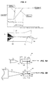
- Fig. 4 is an explanatory diagram illustrating thermal affecting areas to the diaphragm 130 when the outer peripheral part of the power element 100 is subjected to TIG welding or laser welding.
- TIG welding gave the annealing effect to the diaphragm 130 within a range up to about 1.0 mm from the length dimension due to melting of the welding part W.
- the area was 1.0 mm or less and could be small up to about 0.2 mm according to laser welding.
- a distance dimension S 1 from the fulcrum position P1 of the diaphragm 130 to the outer periphery of the power element 100 is set to be a distance obtained by adding from 0.2 mm to 1.0 mm to the length dimension L 2 of the welding part W 2 formed by laser welding.
- the distance S 1 is a half of the difference between the outer diameter dimension D 2 of the power element 100 and the effective diameter dimension D 5 of the diaphragm 130.
- a distance added to the L 2 is preferably about 0.5 ⁇ 0.2 mm, in order to make the outer diameter dimension of the power element 100 as small as possible while avoiding the thermal affection.
- the outer diameter dimension of the power element 100 can be reduced, while securing the effective diameter dimension of the diaphragm 130.
- Fig. 5A illustrates a conventional welding structure in which the welding part W 1 is formed by a torch T 1 in TIG welding.
- the outer diameter dimension D 1 of the power element 100 required for securing the effective diameter D 5 of the diaphragm 130 comes to be large.
- Fig. 5B illustrates a welding structure according to one embodiment of the present invention in which the welding part W 2 is formed by laser beam B 1 irradiated from a laser torch T 2 .
- the outer diameter dimension D 2 of the power element 100 required for securing the effective diameter D 5 of the diaphragm 130 can be small.
- the expansion valve with a small size can be obtained by inserting the power element 100 into the cylindrical part 12 formed at the upper part of the valve main body 10 and fixing the power element 100 by the caulking part 12a.
- the outer diameter of the upper part of the expansion valve is a dimension obtained by adding the value of two times thickness of the caulking part 12a to the outer diameter of the power element 100.
- the outer diameter dimension is large, there is a problem that such a caulking structure is hardly used.
- the caulking structure can be used. Therefore, screw-processing for screwing the valve main body 10 to the power element 100 is not necessary, so that a production cost can be reduced.
- valve rod 60 contacts the diaphragm 130 via the stopper member 62, and the receiving member 120 has a ring shape.
- the receiving member 120 has a ring shape.
- the stopper member 62 contacts the valve main body 10, so that the movement in the valve opening direction is restricted.
- the stopper member 62 contacts the receiving member 120, so that the movement in the valve opening direction is restricted. Therefore, in the above described embodiment, a dimension in the height direction of the expansion valve can be shortened, comparing with the conventional expansion valve.
- the receiving member 120 is not interposed between the stopper member 62 and the valve main body 10, a position in the vertical direction of the stopper member 62 is not affected by the thickness of the receiving member 120.
- the position of the diaphragm 120 can be stable, and fluctuation of each performance can be reduced.
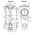
- the present invention can be applied to an expansion valve according to another embodiment having a structure illustrated in Figs. 6A and 6B , in which the power element 100 is screwed to the valve main body 10 by a screw part 120a formed at the receiving member 120 and a screw part 10a formed at the valve main body 10.
Landscapes
- Physics & Mathematics (AREA)
- Engineering & Computer Science (AREA)
- Fluid Mechanics (AREA)
- Mechanical Engineering (AREA)
- Thermal Sciences (AREA)
- General Engineering & Computer Science (AREA)
- Temperature-Responsive Valves (AREA)
- Sealing Battery Cases Or Jackets (AREA)
- Valve Housings (AREA)
Applications Claiming Priority (1)
| Application Number | Priority Date | Filing Date | Title |
|---|---|---|---|
| JP2011063003A JP5730630B2 (ja) | 2011-03-22 | 2011-03-22 | 膨張弁 |
Publications (3)
| Publication Number | Publication Date |
|---|---|
| EP2503267A2 true EP2503267A2 (fr) | 2012-09-26 |
| EP2503267A3 EP2503267A3 (fr) | 2014-03-12 |
| EP2503267B1 EP2503267B1 (fr) | 2020-02-19 |
Family
ID=45445945
Family Applications (1)
| Application Number | Title | Priority Date | Filing Date |
|---|---|---|---|
| EP12150529.1A Active EP2503267B1 (fr) | 2011-03-22 | 2012-01-10 | Vanne d'expansion |
Country Status (3)
| Country | Link |
|---|---|
| EP (1) | EP2503267B1 (fr) |
| JP (1) | JP5730630B2 (fr) |
| CN (1) | CN102692105B (fr) |
Cited By (2)
| Publication number | Priority date | Publication date | Assignee | Title |
|---|---|---|---|---|
| EP3076104A1 (fr) * | 2015-04-03 | 2016-10-05 | Fujikoki Corporation | Élément de puissance de type à fixation de calfeutrage et soupape de détente l'utilisant |
| US11326816B2 (en) | 2017-04-13 | 2022-05-10 | Zhejiang Sanhua Automotive Components Co., Ltd. | Thermal expansion valve |
Families Citing this family (7)
| Publication number | Priority date | Publication date | Assignee | Title |
|---|---|---|---|---|
| CN105402960B (zh) * | 2014-09-09 | 2020-04-10 | 株式会社不二工机 | 膨胀阀 |
| JP6569061B2 (ja) | 2015-08-19 | 2019-09-04 | 株式会社テージーケー | 制御弁 |
| JP6578171B2 (ja) * | 2015-09-17 | 2019-09-18 | 株式会社不二工機 | 膨張弁の製造方法 |
| CN105485982B (zh) * | 2015-12-30 | 2018-04-06 | 浙江新劲空调设备有限公司 | 减振降噪膨胀阀 |
| JP6667753B2 (ja) * | 2016-03-23 | 2020-03-18 | 株式会社テージーケー | 膨張弁 |
| JP6846875B2 (ja) * | 2016-04-26 | 2021-03-24 | 株式会社不二工機 | 膨張弁 |
| CN111720559B (zh) * | 2019-03-20 | 2022-09-23 | 浙江三花汽车零部件有限公司 | 控制阀及空调系统 |
Citations (1)
| Publication number | Priority date | Publication date | Assignee | Title |
|---|---|---|---|---|
| JP2008180475A (ja) | 2007-01-26 | 2008-08-07 | Fuji Koki Corp | 膨張弁 |
Family Cites Families (13)
| Publication number | Priority date | Publication date | Assignee | Title |
|---|---|---|---|---|
| JP3321713B2 (ja) * | 1991-10-17 | 2002-09-09 | イートン コーポレーション | 熱応答形膨張弁 |
| JPH0632973U (ja) * | 1992-10-01 | 1994-04-28 | 株式会社ゼクセル | 膨張弁のパワーエレメント |
| JPH0979703A (ja) * | 1995-09-08 | 1997-03-28 | Denso Corp | 温度式膨張弁 |
| JP3785229B2 (ja) * | 1996-09-12 | 2006-06-14 | 株式会社不二工機 | 膨張弁 |
| JP3392319B2 (ja) * | 1997-05-16 | 2003-03-31 | 太平洋工業株式会社 | 温度式膨張弁の製造方法 |
| JP2002267291A (ja) * | 2001-03-13 | 2002-09-18 | Fuji Koki Corp | 温度膨張弁 |
| AU2003286479A1 (en) * | 2002-10-18 | 2004-05-04 | Parker-Hannifin Corporation | Refrigeration expansion valve with thermal mass power element |
| JP4303637B2 (ja) * | 2004-03-12 | 2009-07-29 | 株式会社テージーケー | 可変容量圧縮機用制御弁 |
| JP2006105474A (ja) * | 2004-10-05 | 2006-04-20 | Tgk Co Ltd | 温度式膨張弁 |
| JP2007032862A (ja) * | 2005-07-22 | 2007-02-08 | Tgk Co Ltd | 膨張弁 |
| JP2007315727A (ja) * | 2006-05-29 | 2007-12-06 | Tgk Co Ltd | 膨張弁 |
| JP2008215797A (ja) * | 2007-02-07 | 2008-09-18 | Tgk Co Ltd | 膨張弁 |
| JP5231073B2 (ja) * | 2008-04-11 | 2013-07-10 | 三菱電機株式会社 | 溶接継手及びその製造方法 |
-
2011
- 2011-03-22 JP JP2011063003A patent/JP5730630B2/ja active Active
- 2011-12-08 CN CN201110406877.7A patent/CN102692105B/zh active Active
-
2012
- 2012-01-10 EP EP12150529.1A patent/EP2503267B1/fr active Active
Patent Citations (1)
| Publication number | Priority date | Publication date | Assignee | Title |
|---|---|---|---|---|
| JP2008180475A (ja) | 2007-01-26 | 2008-08-07 | Fuji Koki Corp | 膨張弁 |
Cited By (4)
| Publication number | Priority date | Publication date | Assignee | Title |
|---|---|---|---|---|
| EP3076104A1 (fr) * | 2015-04-03 | 2016-10-05 | Fujikoki Corporation | Élément de puissance de type à fixation de calfeutrage et soupape de détente l'utilisant |
| CN106051282A (zh) * | 2015-04-03 | 2016-10-26 | 株式会社不二工机 | 铆接固定型动力元件以及使用其的膨胀阀 |
| US10436484B2 (en) | 2015-04-03 | 2019-10-08 | Fujikoki Corporation | Caulking fixation type power element and expansion valve using the same |
| US11326816B2 (en) | 2017-04-13 | 2022-05-10 | Zhejiang Sanhua Automotive Components Co., Ltd. | Thermal expansion valve |
Also Published As
| Publication number | Publication date |
|---|---|
| JP2012197990A (ja) | 2012-10-18 |
| EP2503267A3 (fr) | 2014-03-12 |
| EP2503267B1 (fr) | 2020-02-19 |
| CN102692105B (zh) | 2016-06-22 |
| CN102692105A (zh) | 2012-09-26 |
| JP5730630B2 (ja) | 2015-06-10 |
Similar Documents
| Publication | Publication Date | Title |
|---|---|---|
| EP2503267B1 (fr) | Vanne d'expansion | |
| CN102762935B (zh) | 膨胀阀 | |
| JP6596217B2 (ja) | カシメ固定型パワーエレメント及びこれを用いた膨張弁 | |
| KR20060041893A (ko) | 팽창밸브 | |
| US7185826B2 (en) | Expansion valve | |
| US20020162896A1 (en) | Thermal expansion valve | |
| JP6961232B2 (ja) | パワーエレメントおよびそれを有する膨張弁 | |
| JP5730629B2 (ja) | 膨張弁 | |
| EP1598581B1 (fr) | Vanne d'expansion | |
| US6896190B2 (en) | Expansion valve | |
| JP6523746B2 (ja) | 膨張弁 | |
| JP2018004234A (ja) | 膨張弁 | |
| CN104976834B (zh) | 膨胀阀 | |
| JP6611533B2 (ja) | 膨張弁 | |
| JP2007322058A (ja) | 圧力制御弁 | |
| JP2005249273A (ja) | 温度式膨張弁 | |
| JP2009227027A (ja) | 車両用防水構造 | |
| JP7051091B2 (ja) | 膨張弁 | |
| JP6566715B2 (ja) | 膨張弁 | |
| JP2006322689A (ja) | 温度式膨張弁 | |
| JP2017198373A (ja) | 膨張弁 | |
| JP2004003868A (ja) | 温度式膨張弁 | |
| JP2009109040A (ja) | 温度式膨張弁 | |
| JP2005226941A (ja) | 膨張弁 |
Legal Events
| Date | Code | Title | Description |
|---|---|---|---|
| PUAI | Public reference made under article 153(3) epc to a published international application that has entered the european phase |
Free format text: ORIGINAL CODE: 0009012 |
|
| AK | Designated contracting states |
Kind code of ref document: A2 Designated state(s): AL AT BE BG CH CY CZ DE DK EE ES FI FR GB GR HR HU IE IS IT LI LT LU LV MC MK MT NL NO PL PT RO RS SE SI SK SM TR |
|
| AX | Request for extension of the european patent |
Extension state: BA ME |
|
| PUAL | Search report despatched |
Free format text: ORIGINAL CODE: 0009013 |
|
| AK | Designated contracting states |
Kind code of ref document: A3 Designated state(s): AL AT BE BG CH CY CZ DE DK EE ES FI FR GB GR HR HU IE IS IT LI LT LU LV MC MK MT NL NO PL PT RO RS SE SI SK SM TR |
|
| AX | Request for extension of the european patent |
Extension state: BA ME |
|
| RIC1 | Information provided on ipc code assigned before grant |
Ipc: F25B 41/06 20060101AFI20140205BHEP |
|
| 17P | Request for examination filed |
Effective date: 20140724 |
|
| RBV | Designated contracting states (corrected) |
Designated state(s): AL AT BE BG CH CY CZ DE DK EE ES FI FR GB GR HR HU IE IS IT LI LT LU LV MC MK MT NL NO PL PT RO RS SE SI SK SM TR |
|
| STAA | Information on the status of an ep patent application or granted ep patent |
Free format text: STATUS: EXAMINATION IS IN PROGRESS |
|
| 17Q | First examination report despatched |
Effective date: 20170302 |
|
| GRAP | Despatch of communication of intention to grant a patent |
Free format text: ORIGINAL CODE: EPIDOSNIGR1 |
|
| STAA | Information on the status of an ep patent application or granted ep patent |
Free format text: STATUS: GRANT OF PATENT IS INTENDED |
|
| INTG | Intention to grant announced |
Effective date: 20190718 |
|
| GRAS | Grant fee paid |
Free format text: ORIGINAL CODE: EPIDOSNIGR3 |
|
| GRAA | (expected) grant |
Free format text: ORIGINAL CODE: 0009210 |
|
| STAA | Information on the status of an ep patent application or granted ep patent |
Free format text: STATUS: THE PATENT HAS BEEN GRANTED |
|
| AK | Designated contracting states |
Kind code of ref document: B1 Designated state(s): AL AT BE BG CH CY CZ DE DK EE ES FI FR GB GR HR HU IE IS IT LI LT LU LV MC MK MT NL NO PL PT RO RS SE SI SK SM TR |
|
| REG | Reference to a national code |
Ref country code: GB Ref legal event code: FG4D |
|
| REG | Reference to a national code |
Ref country code: CH Ref legal event code: EP |
|
| REG | Reference to a national code |
Ref country code: DE Ref legal event code: R096 Ref document number: 602012067829 Country of ref document: DE |
|
| REG | Reference to a national code |
Ref country code: AT Ref legal event code: REF Ref document number: 1235430 Country of ref document: AT Kind code of ref document: T Effective date: 20200315 |
|
| REG | Reference to a national code |
Ref country code: IE Ref legal event code: FG4D |
|
| REG | Reference to a national code |
Ref country code: NL Ref legal event code: MP Effective date: 20200219 |
|
| PG25 | Lapsed in a contracting state [announced via postgrant information from national office to epo] |
Ref country code: NO Free format text: LAPSE BECAUSE OF FAILURE TO SUBMIT A TRANSLATION OF THE DESCRIPTION OR TO PAY THE FEE WITHIN THE PRESCRIBED TIME-LIMIT Effective date: 20200519 Ref country code: FI Free format text: LAPSE BECAUSE OF FAILURE TO SUBMIT A TRANSLATION OF THE DESCRIPTION OR TO PAY THE FEE WITHIN THE PRESCRIBED TIME-LIMIT Effective date: 20200219 Ref country code: RS Free format text: LAPSE BECAUSE OF FAILURE TO SUBMIT A TRANSLATION OF THE DESCRIPTION OR TO PAY THE FEE WITHIN THE PRESCRIBED TIME-LIMIT Effective date: 20200219 |
|
| REG | Reference to a national code |
Ref country code: LT Ref legal event code: MG4D |
|
| PG25 | Lapsed in a contracting state [announced via postgrant information from national office to epo] |
Ref country code: HR Free format text: LAPSE BECAUSE OF FAILURE TO SUBMIT A TRANSLATION OF THE DESCRIPTION OR TO PAY THE FEE WITHIN THE PRESCRIBED TIME-LIMIT Effective date: 20200219 Ref country code: IS Free format text: LAPSE BECAUSE OF FAILURE TO SUBMIT A TRANSLATION OF THE DESCRIPTION OR TO PAY THE FEE WITHIN THE PRESCRIBED TIME-LIMIT Effective date: 20200619 Ref country code: BG Free format text: LAPSE BECAUSE OF FAILURE TO SUBMIT A TRANSLATION OF THE DESCRIPTION OR TO PAY THE FEE WITHIN THE PRESCRIBED TIME-LIMIT Effective date: 20200519 Ref country code: GR Free format text: LAPSE BECAUSE OF FAILURE TO SUBMIT A TRANSLATION OF THE DESCRIPTION OR TO PAY THE FEE WITHIN THE PRESCRIBED TIME-LIMIT Effective date: 20200520 Ref country code: SE Free format text: LAPSE BECAUSE OF FAILURE TO SUBMIT A TRANSLATION OF THE DESCRIPTION OR TO PAY THE FEE WITHIN THE PRESCRIBED TIME-LIMIT Effective date: 20200219 Ref country code: LV Free format text: LAPSE BECAUSE OF FAILURE TO SUBMIT A TRANSLATION OF THE DESCRIPTION OR TO PAY THE FEE WITHIN THE PRESCRIBED TIME-LIMIT Effective date: 20200219 |
|
| PG25 | Lapsed in a contracting state [announced via postgrant information from national office to epo] |
Ref country code: NL Free format text: LAPSE BECAUSE OF FAILURE TO SUBMIT A TRANSLATION OF THE DESCRIPTION OR TO PAY THE FEE WITHIN THE PRESCRIBED TIME-LIMIT Effective date: 20200219 |
|
| PG25 | Lapsed in a contracting state [announced via postgrant information from national office to epo] |
Ref country code: RO Free format text: LAPSE BECAUSE OF FAILURE TO SUBMIT A TRANSLATION OF THE DESCRIPTION OR TO PAY THE FEE WITHIN THE PRESCRIBED TIME-LIMIT Effective date: 20200219 Ref country code: LT Free format text: LAPSE BECAUSE OF FAILURE TO SUBMIT A TRANSLATION OF THE DESCRIPTION OR TO PAY THE FEE WITHIN THE PRESCRIBED TIME-LIMIT Effective date: 20200219 Ref country code: CZ Free format text: LAPSE BECAUSE OF FAILURE TO SUBMIT A TRANSLATION OF THE DESCRIPTION OR TO PAY THE FEE WITHIN THE PRESCRIBED TIME-LIMIT Effective date: 20200219 Ref country code: ES Free format text: LAPSE BECAUSE OF FAILURE TO SUBMIT A TRANSLATION OF THE DESCRIPTION OR TO PAY THE FEE WITHIN THE PRESCRIBED TIME-LIMIT Effective date: 20200219 Ref country code: SK Free format text: LAPSE BECAUSE OF FAILURE TO SUBMIT A TRANSLATION OF THE DESCRIPTION OR TO PAY THE FEE WITHIN THE PRESCRIBED TIME-LIMIT Effective date: 20200219 Ref country code: DK Free format text: LAPSE BECAUSE OF FAILURE TO SUBMIT A TRANSLATION OF THE DESCRIPTION OR TO PAY THE FEE WITHIN THE PRESCRIBED TIME-LIMIT Effective date: 20200219 Ref country code: SM Free format text: LAPSE BECAUSE OF FAILURE TO SUBMIT A TRANSLATION OF THE DESCRIPTION OR TO PAY THE FEE WITHIN THE PRESCRIBED TIME-LIMIT Effective date: 20200219 Ref country code: EE Free format text: LAPSE BECAUSE OF FAILURE TO SUBMIT A TRANSLATION OF THE DESCRIPTION OR TO PAY THE FEE WITHIN THE PRESCRIBED TIME-LIMIT Effective date: 20200219 Ref country code: PT Free format text: LAPSE BECAUSE OF FAILURE TO SUBMIT A TRANSLATION OF THE DESCRIPTION OR TO PAY THE FEE WITHIN THE PRESCRIBED TIME-LIMIT Effective date: 20200712 |
|
| REG | Reference to a national code |
Ref country code: AT Ref legal event code: MK05 Ref document number: 1235430 Country of ref document: AT Kind code of ref document: T Effective date: 20200219 |
|
| REG | Reference to a national code |
Ref country code: DE Ref legal event code: R097 Ref document number: 602012067829 Country of ref document: DE |
|
| REG | Reference to a national code |
Ref country code: DE Ref legal event code: R079 Ref document number: 602012067829 Country of ref document: DE Free format text: PREVIOUS MAIN CLASS: F25B0041060000 Ipc: F25B0041300000 |
|
| PLBE | No opposition filed within time limit |
Free format text: ORIGINAL CODE: 0009261 |
|
| STAA | Information on the status of an ep patent application or granted ep patent |
Free format text: STATUS: NO OPPOSITION FILED WITHIN TIME LIMIT |
|
| 26N | No opposition filed |
Effective date: 20201120 |
|
| PG25 | Lapsed in a contracting state [announced via postgrant information from national office to epo] |
Ref country code: AT Free format text: LAPSE BECAUSE OF FAILURE TO SUBMIT A TRANSLATION OF THE DESCRIPTION OR TO PAY THE FEE WITHIN THE PRESCRIBED TIME-LIMIT Effective date: 20200219 |
|
| PG25 | Lapsed in a contracting state [announced via postgrant information from national office to epo] |
Ref country code: PL Free format text: LAPSE BECAUSE OF FAILURE TO SUBMIT A TRANSLATION OF THE DESCRIPTION OR TO PAY THE FEE WITHIN THE PRESCRIBED TIME-LIMIT Effective date: 20200219 Ref country code: SI Free format text: LAPSE BECAUSE OF FAILURE TO SUBMIT A TRANSLATION OF THE DESCRIPTION OR TO PAY THE FEE WITHIN THE PRESCRIBED TIME-LIMIT Effective date: 20200219 |
|
| PG25 | Lapsed in a contracting state [announced via postgrant information from national office to epo] |
Ref country code: MC Free format text: LAPSE BECAUSE OF FAILURE TO SUBMIT A TRANSLATION OF THE DESCRIPTION OR TO PAY THE FEE WITHIN THE PRESCRIBED TIME-LIMIT Effective date: 20200219 |
|
| REG | Reference to a national code |
Ref country code: CH Ref legal event code: PL |
|
| PG25 | Lapsed in a contracting state [announced via postgrant information from national office to epo] |
Ref country code: LU Free format text: LAPSE BECAUSE OF NON-PAYMENT OF DUE FEES Effective date: 20210110 |
|
| REG | Reference to a national code |
Ref country code: BE Ref legal event code: MM Effective date: 20210131 |
|
| PG25 | Lapsed in a contracting state [announced via postgrant information from national office to epo] |
Ref country code: LI Free format text: LAPSE BECAUSE OF NON-PAYMENT OF DUE FEES Effective date: 20210131 Ref country code: CH Free format text: LAPSE BECAUSE OF NON-PAYMENT OF DUE FEES Effective date: 20210131 |
|
| PG25 | Lapsed in a contracting state [announced via postgrant information from national office to epo] |
Ref country code: IE Free format text: LAPSE BECAUSE OF NON-PAYMENT OF DUE FEES Effective date: 20210110 |
|
| PG25 | Lapsed in a contracting state [announced via postgrant information from national office to epo] |
Ref country code: BE Free format text: LAPSE BECAUSE OF NON-PAYMENT OF DUE FEES Effective date: 20210131 |
|
| REG | Reference to a national code |
Ref country code: DE Ref legal event code: R082 Ref document number: 602012067829 Country of ref document: DE Representative=s name: SCHWEIGER, MARTIN, DIPL.-ING. UNIV., DE Ref country code: DE Ref legal event code: R082 Ref document number: 602012067829 Country of ref document: DE Representative=s name: WUNDERLICH & HEIM PATENTANWAELTE PARTNERSCHAFT, DE |
|
| PG25 | Lapsed in a contracting state [announced via postgrant information from national office to epo] |
Ref country code: HU Free format text: LAPSE BECAUSE OF FAILURE TO SUBMIT A TRANSLATION OF THE DESCRIPTION OR TO PAY THE FEE WITHIN THE PRESCRIBED TIME-LIMIT; INVALID AB INITIO Effective date: 20120110 Ref country code: CY Free format text: LAPSE BECAUSE OF FAILURE TO SUBMIT A TRANSLATION OF THE DESCRIPTION OR TO PAY THE FEE WITHIN THE PRESCRIBED TIME-LIMIT Effective date: 20200219 |
|
| PG25 | Lapsed in a contracting state [announced via postgrant information from national office to epo] |
Ref country code: MK Free format text: LAPSE BECAUSE OF FAILURE TO SUBMIT A TRANSLATION OF THE DESCRIPTION OR TO PAY THE FEE WITHIN THE PRESCRIBED TIME-LIMIT Effective date: 20200219 |
|
| PG25 | Lapsed in a contracting state [announced via postgrant information from national office to epo] |
Ref country code: TR Free format text: LAPSE BECAUSE OF FAILURE TO SUBMIT A TRANSLATION OF THE DESCRIPTION OR TO PAY THE FEE WITHIN THE PRESCRIBED TIME-LIMIT Effective date: 20200219 |
|
| REG | Reference to a national code |
Ref country code: DE Ref legal event code: R082 Ref document number: 602012067829 Country of ref document: DE Representative=s name: WUNDERLICH & HEIM PATENTANWAELTE PARTNERSCHAFT, DE |
|
| PG25 | Lapsed in a contracting state [announced via postgrant information from national office to epo] |
Ref country code: MT Free format text: LAPSE BECAUSE OF FAILURE TO SUBMIT A TRANSLATION OF THE DESCRIPTION OR TO PAY THE FEE WITHIN THE PRESCRIBED TIME-LIMIT Effective date: 20200219 |
|
| PGFP | Annual fee paid to national office [announced via postgrant information from national office to epo] |
Ref country code: GB Payment date: 20251127 Year of fee payment: 15 |
|
| PGFP | Annual fee paid to national office [announced via postgrant information from national office to epo] |
Ref country code: FR Payment date: 20251128 Year of fee payment: 15 |
|
| PGFP | Annual fee paid to national office [announced via postgrant information from national office to epo] |
Ref country code: DE Payment date: 20251203 Year of fee payment: 15 |
|
| PGFP | Annual fee paid to national office [announced via postgrant information from national office to epo] |
Ref country code: IT Payment date: 20251219 Year of fee payment: 15 |