EP2507474B1 - Dispositif et procédé d'extraction, notamment d'extraction in-situ, d'une substance carbonée située dans un gisement souterrain - Google Patents
Dispositif et procédé d'extraction, notamment d'extraction in-situ, d'une substance carbonée située dans un gisement souterrain Download PDFInfo
- Publication number
- EP2507474B1 EP2507474B1 EP11701823.4A EP11701823A EP2507474B1 EP 2507474 B1 EP2507474 B1 EP 2507474B1 EP 11701823 A EP11701823 A EP 11701823A EP 2507474 B1 EP2507474 B1 EP 2507474B1
- Authority
- EP
- European Patent Office
- Prior art keywords
- liquid
- reservoir
- conductor
- carrying conduit
- pressure
- Prior art date
- Legal status (The legal status is an assumption and is not a legal conclusion. Google has not performed a legal analysis and makes no representation as to the accuracy of the status listed.)
- Not-in-force
Links
- 238000000034 method Methods 0.000 title claims description 24
- 238000011065 in-situ storage Methods 0.000 title description 7
- 239000003575 carbonaceous material Substances 0.000 title description 3
- 239000007788 liquid Substances 0.000 claims description 291
- 239000004020 conductor Substances 0.000 claims description 112
- 239000000126 substance Substances 0.000 claims description 27
- 230000001965 increasing effect Effects 0.000 claims description 26
- XLYOFNOQVPJJNP-UHFFFAOYSA-N water Substances O XLYOFNOQVPJJNP-UHFFFAOYSA-N 0.000 claims description 25
- 239000010426 asphalt Substances 0.000 claims description 19
- 239000000295 fuel oil Substances 0.000 claims description 12
- 239000000110 cooling liquid Substances 0.000 claims description 10
- 238000009826 distribution Methods 0.000 claims description 7
- 239000002904 solvent Substances 0.000 claims description 7
- ATUOYWHBWRKTHZ-UHFFFAOYSA-N Propane Chemical compound CCC ATUOYWHBWRKTHZ-UHFFFAOYSA-N 0.000 claims description 6
- VNWKTOKETHGBQD-UHFFFAOYSA-N methane Chemical compound C VNWKTOKETHGBQD-UHFFFAOYSA-N 0.000 claims description 6
- 229930195733 hydrocarbon Natural products 0.000 claims description 5
- 150000002430 hydrocarbons Chemical class 0.000 claims description 5
- 239000004576 sand Substances 0.000 claims description 4
- 239000002253 acid Substances 0.000 claims description 3
- 150000007513 acids Chemical class 0.000 claims description 3
- 239000001273 butane Substances 0.000 claims description 3
- 230000002706 hydrostatic effect Effects 0.000 claims description 3
- IJDNQMDRQITEOD-UHFFFAOYSA-N n-butane Chemical compound CCCC IJDNQMDRQITEOD-UHFFFAOYSA-N 0.000 claims description 3
- OFBQJSOFQDEBGM-UHFFFAOYSA-N n-pentane Natural products CCCCC OFBQJSOFQDEBGM-UHFFFAOYSA-N 0.000 claims description 3
- 239000001294 propane Substances 0.000 claims description 3
- 239000007787 solid Substances 0.000 claims description 3
- 150000001335 aliphatic alkanes Chemical class 0.000 claims description 2
- 238000000605 extraction Methods 0.000 claims description 2
- 238000001816 cooling Methods 0.000 description 38
- 238000010438 heat treatment Methods 0.000 description 23
- 239000003921 oil Substances 0.000 description 18
- 238000004519 manufacturing process Methods 0.000 description 17
- 239000002826 coolant Substances 0.000 description 12
- 239000012530 fluid Substances 0.000 description 12
- 230000000694 effects Effects 0.000 description 11
- 238000002347 injection Methods 0.000 description 10
- 239000007924 injection Substances 0.000 description 10
- 239000007789 gas Substances 0.000 description 9
- 230000001939 inductive effect Effects 0.000 description 8
- 239000000203 mixture Substances 0.000 description 8
- 238000009835 boiling Methods 0.000 description 7
- 238000006073 displacement reaction Methods 0.000 description 7
- 230000002829 reductive effect Effects 0.000 description 7
- 230000008901 benefit Effects 0.000 description 6
- 239000003792 electrolyte Substances 0.000 description 6
- 230000008569 process Effects 0.000 description 6
- 238000009413 insulation Methods 0.000 description 5
- 239000011148 porous material Substances 0.000 description 5
- 150000003839 salts Chemical class 0.000 description 5
- 238000011084 recovery Methods 0.000 description 4
- 238000009434 installation Methods 0.000 description 3
- 239000004058 oil shale Substances 0.000 description 3
- 238000013021 overheating Methods 0.000 description 3
- 230000036961 partial effect Effects 0.000 description 3
- 239000004033 plastic Substances 0.000 description 3
- 238000012545 processing Methods 0.000 description 3
- 239000000243 solution Substances 0.000 description 3
- 125000006850 spacer group Chemical group 0.000 description 3
- CURLTUGMZLYLDI-UHFFFAOYSA-N Carbon dioxide Chemical compound O=C=O CURLTUGMZLYLDI-UHFFFAOYSA-N 0.000 description 2
- LYCAIKOWRPUZTN-UHFFFAOYSA-N Ethylene glycol Chemical compound OCCO LYCAIKOWRPUZTN-UHFFFAOYSA-N 0.000 description 2
- 230000008859 change Effects 0.000 description 2
- 229910052729 chemical element Inorganic materials 0.000 description 2
- 230000001143 conditioned effect Effects 0.000 description 2
- 238000010276 construction Methods 0.000 description 2
- 230000001419 dependent effect Effects 0.000 description 2
- 238000010612 desalination reaction Methods 0.000 description 2
- 238000011033 desalting Methods 0.000 description 2
- 238000013461 design Methods 0.000 description 2
- 238000011161 development Methods 0.000 description 2
- 230000018109 developmental process Effects 0.000 description 2
- 239000012212 insulator Substances 0.000 description 2
- 239000000463 material Substances 0.000 description 2
- 239000003027 oil sand Substances 0.000 description 2
- 230000035515 penetration Effects 0.000 description 2
- 230000001681 protective effect Effects 0.000 description 2
- 239000011435 rock Substances 0.000 description 2
- 238000000926 separation method Methods 0.000 description 2
- 239000002689 soil Substances 0.000 description 2
- 238000003860 storage Methods 0.000 description 2
- 238000012546 transfer Methods 0.000 description 2
- 239000004215 Carbon black (E152) Substances 0.000 description 1
- 240000003517 Elaeocarpus dentatus Species 0.000 description 1
- 238000010793 Steam injection (oil industry) Methods 0.000 description 1
- 239000007798 antifreeze agent Substances 0.000 description 1
- 238000013459 approach Methods 0.000 description 1
- 239000007864 aqueous solution Substances 0.000 description 1
- 230000000712 assembly Effects 0.000 description 1
- 238000000429 assembly Methods 0.000 description 1
- 230000015572 biosynthetic process Effects 0.000 description 1
- 239000003795 chemical substances by application Substances 0.000 description 1
- 150000001875 compounds Chemical class 0.000 description 1
- 239000000470 constituent Substances 0.000 description 1
- 239000012809 cooling fluid Substances 0.000 description 1
- 230000003247 decreasing effect Effects 0.000 description 1
- 230000000593 degrading effect Effects 0.000 description 1
- 239000003085 diluting agent Substances 0.000 description 1
- 238000010292 electrical insulation Methods 0.000 description 1
- 230000005674 electromagnetic induction Effects 0.000 description 1
- 239000000839 emulsion Substances 0.000 description 1
- 230000007613 environmental effect Effects 0.000 description 1
- 238000001704 evaporation Methods 0.000 description 1
- 230000008020 evaporation Effects 0.000 description 1
- 238000009422 external insulation Methods 0.000 description 1
- 238000011010 flushing procedure Methods 0.000 description 1
- 238000005755 formation reaction Methods 0.000 description 1
- 230000020169 heat generation Effects 0.000 description 1
- WGCNASOHLSPBMP-UHFFFAOYSA-N hydroxyacetaldehyde Natural products OCC=O WGCNASOHLSPBMP-UHFFFAOYSA-N 0.000 description 1
- 230000006872 improvement Effects 0.000 description 1
- 230000006698 induction Effects 0.000 description 1
- 239000004615 ingredient Substances 0.000 description 1
- 230000000670 limiting effect Effects 0.000 description 1
- 230000007774 longterm Effects 0.000 description 1
- 238000007726 management method Methods 0.000 description 1
- 238000002844 melting Methods 0.000 description 1
- 230000008018 melting Effects 0.000 description 1
- 239000002184 metal Substances 0.000 description 1
- 239000002245 particle Substances 0.000 description 1
- 230000035699 permeability Effects 0.000 description 1
- 238000002360 preparation method Methods 0.000 description 1
- 230000009467 reduction Effects 0.000 description 1
- 230000002441 reversible effect Effects 0.000 description 1
- 210000002023 somite Anatomy 0.000 description 1
- 239000003381 stabilizer Substances 0.000 description 1
- 230000000087 stabilizing effect Effects 0.000 description 1
- 239000000758 substrate Substances 0.000 description 1
- 239000002918 waste heat Substances 0.000 description 1
- 239000002351 wastewater Substances 0.000 description 1
- 238000010626 work up procedure Methods 0.000 description 1
Images



Classifications
-
- E—FIXED CONSTRUCTIONS
- E21—EARTH OR ROCK DRILLING; MINING
- E21B—EARTH OR ROCK DRILLING; OBTAINING OIL, GAS, WATER, SOLUBLE OR MELTABLE MATERIALS OR A SLURRY OF MINERALS FROM WELLS
- E21B43/00—Methods or apparatus for obtaining oil, gas, water, soluble or meltable materials or a slurry of minerals from wells
- E21B43/16—Enhanced recovery methods for obtaining hydrocarbons
- E21B43/24—Enhanced recovery methods for obtaining hydrocarbons using heat, e.g. steam injection
- E21B43/2401—Enhanced recovery methods for obtaining hydrocarbons using heat, e.g. steam injection by means of electricity
-
- C—CHEMISTRY; METALLURGY
- C09—DYES; PAINTS; POLISHES; NATURAL RESINS; ADHESIVES; COMPOSITIONS NOT OTHERWISE PROVIDED FOR; APPLICATIONS OF MATERIALS NOT OTHERWISE PROVIDED FOR
- C09K—MATERIALS FOR MISCELLANEOUS APPLICATIONS, NOT PROVIDED FOR ELSEWHERE
- C09K8/00—Compositions for drilling of boreholes or wells; Compositions for treating boreholes or wells, e.g. for completion or for remedial operations
- C09K8/58—Compositions for enhanced recovery methods for obtaining hydrocarbons, i.e. for improving the mobility of the oil, e.g. displacing fluids
- C09K8/592—Compositions used in combination with generated heat, e.g. by steam injection
-
- E—FIXED CONSTRUCTIONS
- E21—EARTH OR ROCK DRILLING; MINING
- E21B—EARTH OR ROCK DRILLING; OBTAINING OIL, GAS, WATER, SOLUBLE OR MELTABLE MATERIALS OR A SLURRY OF MINERALS FROM WELLS
- E21B17/00—Drilling rods or pipes; Flexible drill strings; Kellies; Drill collars; Sucker rods; Cables; Casings; Tubings
- E21B17/18—Pipes provided with plural fluid passages
-
- E—FIXED CONSTRUCTIONS
- E21—EARTH OR ROCK DRILLING; MINING
- E21B—EARTH OR ROCK DRILLING; OBTAINING OIL, GAS, WATER, SOLUBLE OR MELTABLE MATERIALS OR A SLURRY OF MINERALS FROM WELLS
- E21B34/00—Valve arrangements for boreholes or wells
- E21B34/06—Valve arrangements for boreholes or wells in wells
-
- E—FIXED CONSTRUCTIONS
- E21—EARTH OR ROCK DRILLING; MINING
- E21B—EARTH OR ROCK DRILLING; OBTAINING OIL, GAS, WATER, SOLUBLE OR MELTABLE MATERIALS OR A SLURRY OF MINERALS FROM WELLS
- E21B43/00—Methods or apparatus for obtaining oil, gas, water, soluble or meltable materials or a slurry of minerals from wells
- E21B43/30—Specific pattern of wells, e.g. optimising the spacing of wells
- E21B43/305—Specific pattern of wells, e.g. optimising the spacing of wells comprising at least one inclined or horizontal well
Definitions
- the invention relates to an installation for the in situ recovery of a carbonaceous substance from an underground deposit with reduction of its viscosity.
- a device is used in particular for the production of bitumen or heavy oil from a reservoir under an overburden, as is the case with oil shale and / or oil sand deposits, for example in Canada.
- SAGD S team A ssisted G ravity D rainage
- water vapor which may be added to the solvent, is pressed under high pressure through a tube extending horizontally within the seam.
- the heated, molten bitumen or heavy oil removed from the sand or rock seeps to a second pipe located about 5 m lower, through which the liquefied bitumen or heavy oil is conveyed, the distance between injector and production pipe being dependent on reservoir geometry.
- the steam has to fulfill several tasks at the same time, namely the introduction of heating energy for liquefaction, the detachment of the sand and the pressure build-up in the reservoir, on the one hand to make the reservoir geomechanically permeable for bitumen transport (permeability) and on the other hand, the promotion of bitumen without additional pumps to enable.
- the SAGD process starts by introducing steam through both pipes, for example for three months, in order first to liquefy the bitumen in the space between the pipes as quickly as possible. Thereafter, the steam is introduced only through the upper tube and the promotion through the lower tube can begin.
- German patent application DE 10 2007 008 292 A1 It is already stated that the SAGD method commonly used for this purpose can be completed with an inductive heating device. Furthermore, in the German patent application DE 10 2007 036 832 A1 a device described in the parallel inductor or electrode assemblies are present, which are connected above ground to an oscillator or inverter.
- German patent applications DE 10 2007 008 292 A1 and DE 10 2007 036 832 A1 So it is proposed to superimpose the steam input with an inductive heating of the deposit.
- resistive heating between two electrodes may additionally be carried out.
- a variation of the heating power along the inductors can, as described in the earlier applications, be carried out specifically by sectionwise injection of electrolytes, whereby the impedance is changed. This requires corresponding electrolyte injection devices whose installation can be complicated or costly.
- a device for conveying a hydrocarbon-containing substance, in particular bitumen or heavy oil is provided from a reservoir, wherein the Reservoir with heat energy to reduce the viscosity of the substance is acted on, including at least one conductor loop for inductive energization of the reservoir is provided as electrical / electromagnetic heating of the reservoir, wherein a conductor - an inductor - the conductor loop is surrounded in at least a portion of a liquid guide and the liquid guide is perforated, so that when a liquid is supplied, the liquid penetrates via a perforation from the liquid guide into the reservoir.
- the invention is therefore an "in situ” promotion, ie the promotion of the hydrocarbonaceous substance directly from the reservoir in which this substance is enriched without degrading the reservoir in the open pit.
- a reservoir is preferably understood an oil sands deposit that can be found underground.
- no introduction of steam via the liquid guide is provided.
- a combination may additionally be advantageous with the SAGD method, for example cooling the inductor according to the device according to the invention and introducing steam via a further tube or a further tube.
- the section of the conductor means a section of the conductor. Assuming that the conductor is essentially a twisted cable encased in a tubular sheath, the portion of the conductor means a section along the length of the cable and sheath.
- a conductor in particular a serial resonant circuit or a part thereof is understood, which is brought in a cable-like structure with external insulation. This is according to the invention surrounded by a liquid guide.
- the liquid guide is an extended hollow body - for example, a tube or a tube - to understand, can be transported through the liquid.
- the electrical conductivity in the immediate vicinity of the conductor can be reduced, thus reducing the geometry-related high heating power density directly at the conductor. It is thus possible to achieve a more homogeneous heating power density in the reservoir.
- the cooling is particularly advantageous for larger storage depths - about greater than 130 m - advantageous because otherwise it could lead to overheating of the inductor, for example, at temperatures of about 200 ° C or more.
- a plastic insulation of the inductor could not permanently withstand such a high temperature. It should be noted here that the boiling point of water in the reservoir at a depth of 130 m or more can be around 200 ° C.
- the heat of the conductor comprises heat due to ohmic losses in the conductor, but more importantly, the heat from the reservoir, which the conductor would receive from the reservoir without corresponding cooling from the environment, can be more significant.
- the inventive idea is based essentially on a fluid guide with a closed fluid circuit in which cool liquid flows along the conductor within the fluid guide, is heated in the reservoir and is led out of the reservoir again.
- the additional inventive concept is explained, in which additionally or alternatively to the cooling, the liquid is fed via the liquid guide into the reservoir and is distributed there in the ground, in order to achieve further effects - for example the improvement of the conductivity in the reservoir.
- the liquid guide and the conductor may be arranged to each other such that a liquid in the liquid guide causes cooling of the conductor. It is irrelevant whether it is the conductor's own waste heat or whether it is heat acting on the conductor from the outside, from the reservoir heated by the current-carrying conductor.
- the cooling effect can be enhanced by movement of the liquid, in particular along the conductor and with circulation or exchange of the liquid, since warm liquid is thereby conducted away and cool liquid can flow.
- the liquid guide may be part of a substantially closed liquid circuit, in which a means for heat exchange - in particular on the surface and not within the reservoir - is provided to cool a liquid heated within the liquid guide again ,
- the re-cooling of the liquid can be effected by tubes which pass through colder region of the reservoir, i.
- the liquid is not brought to the surface, but circulates only in the depth.
- the liquid guide may be formed as a tube and / or tube, wherein the conductor is disposed within the tube or the tube, in particular so that when supplied with a liquid, the conductor is surrounded by the liquid.
- the conductor is disposed within the tube or the tube, in particular so that when supplied with a liquid, the conductor is surrounded by the liquid.
- the tube and / or the tube can be arranged approximately coaxially centered to the conductor, wherein in particular at least one web within the tube or the tube for fixing or positioning of the conductor or for stabilizing the position of the conductor inside the tube or of the pipe is provided.
- a web can also have an axial extent, which even extends in a particular embodiment over the entire length of the hose / tube.
- the conductor may also be freely movable within the tube or tube, i. the conductor is uncentered in the tube or in the tube and means for fixing is omitted.
- the liquid guide may be formed as a plurality of hoses and / or tubes.
- a plurality of capillaries and / or a porous material may be provided to transport the liquid in the liquid guide.
- These variants are preferably arranged such that the conductor is surrounded by the plurality of tubes and / or tubes and / or capillaries and / or the porous material, wherein preferably the plurality of tubes and / or tubes and / or capillaries and / or the porous material and the conductor are arranged within a common tubular outer shell.
- These mentioned means for guiding the liquid are in particular all parallel to each other or twisted.
- a conductor is composed of a multiplicity of partial conductors and these partial conductors can be arranged around the fluid guide.
- the liquid guide in the form of the plurality of hoses and / or tubes may be formed such that at least a first tube and / or tube is provided, in which the liquid in opposite directions to a flow direction of the liquid in at least one second hose and / or pipe flows.
- a closed circuit can be formed.
- two bodies above ground liquid in the liquid guide are pumped from each of the two places only a subset of the available tubes or tubes are filled.
- a more homogeneous temperature along the conductor is achieved with an opposite cooling liquid guide.
- thermally insulating means In an extension can be arranged between the liquid guide and the reservoir, in particular between the liquid guide and the outer shell, thermally insulating means, wherein the thermally insulating means is in particular designed as an air- or gas-filled or as a vacuum-enclosing cavity.
- the thermal insulation of the liquid guide against the reservoir proves to be particularly advantageous, since in a suitable embodiment, the inductively introduced heating power is dissipated again only to the lowest possible proportion by the liquid cooling.
- a pressure increasing means for increasing the pressure of a liquid or for circulating the liquid may be provided, in particular a pump, so that by means of the pressure increasing means, a movement of the liquid is achieved in the liquid guide. In this way, a cooling circuit can be operated.
- thermosyphon - may be provided.
- a reservoir for the liquid in addition to the liquid guide and the pump may be in particular a reservoir for the liquid, a heat exchanger and other above-ground or underground hydraulic connections.
- the reservoir can be carried out either under atmospheric pressure or as a pressure vessel.
- a pressure holder may be provided by means of which the liquid is kept at a higher pressure level as a coolant is circulated and under high pressure level, to avoid boiling at high power input.
- the overall system has a return for the liquid to the surface.
- the invention is particularly advantageous when the liquid guide has a perforation, so that when a liquid is supplied, the liquid from the liquid guide can penetrate into the reservoir, and the perforation in turn has holes that configured in shape and / or size and / or distribution can be that when supplying a liquid under a predetermined pressure, the conductor over the entire length of the area surrounded by the liquid guide portion of the conductor loop is sufficiently cooled.
- liquid guide being sufficiently filled with liquid throughout the length and / or liquid heated by the conductor being led away from the liquid guide through the holes.
- a required amount of low temperature cooling liquid may flow through the liquid guide.
- the above-mentioned effect is preferably obtained when the pressure applied to the liquid in the liquid guide via the feed is adapted to a predetermined perforation in such a manner that leakage of the liquid through the perforation is ensured over a longer period of use.
- liquid conducted through the liquid guide system thermally insulates an environment in the reservoir and / or that the conductor is cooled by the liquid conducted through the liquid guide.
- Water may be provided as liquid for cooling, in particular desalted and / or descaled and / or mixed with an antifreeze agent - e.g. Glycol.
- an antifreeze agent e.g. Glycol.
- salt water, oil, emulsions or solutions may be provided.
- the basic form for the liquid may preferably be an extracted liquid which can be precipitated from the desired delivery material conveyed from the reservoir.
- the liquid guide is perforated, so that when a liquid is supplied, the liquid from the liquid guide penetrates or is introduced through the perforation into the reservoir.
- perforation is meant, for example, holes or slits located in a liquid guide, so that liquid can escape from the interior of the liquid guide to the outside in the vicinity of the holes or slots.
- the fluid guide consists at least partially of porous material or capillaries, so that the fluid can be released by these means to the environment.
- the introduction of the liquid into the reservoir can thereby increase the electrical conductivity of the reservoir and / or increase the pressure in the reservoir.
- a pressure increasing means can be provided for increasing the pressure of a liquid or for circulating the liquid, in particular a pump, so that a fluid with increased pressure can be introduced into the fluid guide by means of the pressure increasing means.
- so much pressure is to be generated by the pump that a predetermined amount of liquid penetrates into the reservoir via the perforation.
- increase pressure is thus meant that an ambient pressure in the reservoir should be overcome.
- the hydrostatic pressure in the reservoir in the vicinity of the perforation should be exceeded so that the liquid can escape, which can be achieved for example with a pressure of 10,000 hPa (10 bar) to 50,000 hPa (50 bar).
- the perforation may be formed and / or means may be provided for the penetration of solids and / or sands from the reservoir in the Is substantially prevented.
- Such agents are known, for example, by the term "Gravel Pack".
- the invention is particularly advantageous when the perforation has holes that can be configured in shape and / or size and / or distribution such that when a liquid is supplied under a predetermined pressure, the liquid distributed over a length of the liquid guide through the perforation into an environment the conductor loop is discharged in the reservoir, so that the electrical conductivity of the reservoir changes and / or the pressure in the reservoir is increased.
- the liquid can be controlled so that the electrical conductivity within the reservoir in its embedding is predominantly increased and / or that the electrical conductivity in the reservoir in the immediate vicinity of the conductor is lowered.
- the perforation should be designed so that the entire length of the liquid guide - except for the supply from the surface to the target region in the reservoir - delivered in each section the same amount of liquid.
- the increase in the pressure in the reservoir is particularly advantageous in that it better displaces the hydrocarbonaceous substance in the reservoir and / or avoids a negative pressure in the reservoir due to the delivery of the substance.
- water or an organic or inorganic solution as the electrolyte in particular also for increasing the conductivity, is suitable as the liquid to be supplied.
- the liquid may preferably have at least one of the following constituents: salts, weak acids, weak bases, CO 2 , or solvents which in particular contain alkanes, for example methane, propane, butane.
- a valve of a production tubing for carrying the liquefied hydrocarbonaceous substance out of the reservoir may be closed and opened at a later time, depending on the attainment of a predetermined period of time or upon reaching a predetermined pressure within the reservoir.
- the pressure can be increased because no material leaves the reservoir and additional liquid is introduced.
- liquid guides may be provided for the conductor loop, each for one half of the conductor loop, with the two liquid guides terminating in the reservoir without the liquid being pumped back to the surface.
- composition may have the liquid which is fed into the reservoir in liquid form. It is particularly advantageous if the liquid is at least partially or completely extracted from the funded water-oil / bitumen mixture.
- the desired substance to be conveyed should be separated from the extracted water-oil / bitumen mixture and the aqueous residue should be post-processed or be prepared.
- this can be done in a much simpler way compared to the injection of water vapor.
- a desalting of the residual liquid can be provided after desanding, so that there is no excessively high salt concentration in the reservoir by continuously introducing the treated residual liquid.
- the viscosity within the reservoir can be reduced, ie the flow properties of bitumen can be improved. In addition, there is an increase in the stability of the reservoir.
- a heat exchanger can also be provided in order to bring the treated residual liquid to a higher temperature in order to prevent undesirable cooling of the reservoir, with the result of a pressure drop or an increase in viscosity.
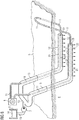
- FIG. 1 shows, schematically illustrated, an apparatus for in situ recovery of a hydrocarbonaceous substance from an underground reservoir 6 as a reservoir while reducing its viscosity, wherein cooling of inductors 10 is provided.
- a device for recovering bitumen from an oil sands deposit.
- the deposit 6 may be, in particular, an oil sands deposit or an oil shale occurrence from which bitumen or other heavy oils may be recovered.
- a tube 9 for introducing steam is shown, which is arranged substantially between parallel sections of an inductor 10 within the reservoir 6 and which is fed via a steam generator 8.
- a steam generator 8 By means distributed over the length of the tube arranged nozzles - not shown - the steam is pressed into the reservoir 6.
- the apparatus for in situ recovery of a hydrocarbonaceous substance further comprises an inductor 10 extending into wells within the reservoir 6.
- the inductor 10 or portions thereof are considered to be the inventive conductor. It is formed a closed loop conductor, which consists of the two horizontally extending in the reservoir 6 back and forth conductors of the inductor 10, and of conductor pieces 11 which act little or little as a heater and run above ground or from the earth's surface 5 into the deposit 6 to ensure the power connection for the inductor 10.
- both loop ends of the conductor loop are arranged above ground.
- the loop is simply closed by - see ladder 11 in the figure.
- an electrical supply 1 including all necessary electrical equipment such as inverter and generator, through which the necessary power and the necessary voltage is applied to the conductor loop, so that the inductors 10 as a conductor serve for an electric / electromagnetic heater for heat generation in the storage site 6.
- the inductors 10 are effective against at least parts of the deposit 6 as an inductive electric heater. Due to the conductivity of at least parts of the deposit 6, this can be heated by the largely concentric around the two as possible parallel sections of the inductor 10.
- the conductor loop can be greatly reduced in areas where they run outside the actual deposit 6 - as the conductor pieces 11 - by means of suitable guidance in their heating capacity. In this way, the heating power can be introduced in defined areas of the deposit 6.
- the inductor 10 may be rod-shaped metallic conductors or twisted metallic cables made of a metal that is in particular highly conductive, which are formed as a resonant circuit.
- a cooling circuit is provided to cool the inductor 10.
- the cooling circuit comprises a liquid guide 12 which according to the figure almost completely surrounds the conductor loop along its length. Much is merely a sheath of the inductor 10. A sheath outside the deposit 6 is not necessary, but may be advantageous, since thereby the laying of the liquid guide 12 can be done together with the conductor loop, thus allowing a simplified installation.
- the sections of the cooling circuit which are not explicitly intended for cooling, are marked as liquid inlets / outlets 13.
- the liquid circuit On the left side of the liquid circuit is closed only in a simple manner to a ring, so that by a first Liquid guide 12 along a first portion of the inductor 10 passed liquid through a second liquid guide 12 along a second portion of the inductor 10 is returned.
- the components to provide the liquid On the right side of the figure are above ground, the components to provide the liquid. These are a reservoir 3, in which the liquid 14 is located for cooling.
- a pump 2 is provided to pump the liquid 14 into the cooling circuit and to ensure a flow rate.
- a recooler 4 is provided, through which the heated cooling liquid can be cooled down.
- the liquid guide 12 is formed in the figure as a coaxial sheathing to the inductor 10, so that the inductor 10 - or a sheath of the inductor 10 - is surrounded as completely as possible during operation of a cooling liquid.
- the device may be operated such that when current is applied to the inductor 10, which heats the vicinity of the inductor 10 in the reservoir 6, a cooling fluid is always conducted through the fluid guide 12 along the inductor 10.
- the inductor 10 heats the bottom in the vicinity of the inductor 10, whereby the heated floor itself becomes the thermal radiator.
- the inductor 10 is to be protected from elevated temperatures. This is done by the cooling liquid in the liquid guide 12 in the form of the described external cooling of the inductor 10, whereby on the one hand the inductor 10 thermally insulated and on the other hand the temperature absorbed by the inductor 10 is dissipated again, so that the inductor 10 does not heat or at least only slightly or to a lesser extent.
- the liquid guide 12 may be additionally sheathed by a thermal insulator.
- the inductor 10 is integrated with the liquid guide 12 and may be laid as a unit. Various configurations of such combined conductors and cooling are explained below.
- FIG. 2 a section of an inductor 10 with a surrounding cooling is schematically illustrated in a perspective view.
- An inductor 10 centered in a tubular jacket 15 of the liquid guide 12 is surrounded by a liquid guide 12.
- the positioning of the inductor 10 may for example be determined solely by the flowing liquid in the liquid guide 12. On a centering is according to FIG. 2 waived.
- the inductor 10 is accordingly largely freely movable in the liquid guide 12 and could, for example, also come to rest on the liquid casing due to the weight force.
- For a specific positioning or fixation in the Liquid guide 12, however, are presented below various embodiments.
- the diameter of the inductor 10 may preferably be 30 to 100 mm.
- the annular gap width of the inductor 10 will preferably be 5 mm to 50 mm and the mass flow of the cooling medium within the liquid guide 12 preferably 5 to 100 1 / min.
- cross sections of cooled conductors are schematically illustrated.
- the cross section is taken along a cut surface, as in FIG. 1 is indicated by AA.
- a support of the inductor 10 by, for example, star-shaped spacers - webs 16 -, wherein preferably 2 to 5 spacers are used.
- the webs 16 are preferably attached to the inner wall of the shell 15 and are connected in the center via stabilizers 17 or attached directly to the outer shell of the inductor 10.
- the inductor 10 is located coaxially in the center of the casing 15 of the liquid guide 12 and is either laid as a unit with the casing 15 and the webs 16 or is subsequently retracted.
- the liquid guide 12 results from the cavities within the casing 15th
- the width of the webs 16 may, for example, in the range 5-30 mm, so that the pressure losses of the cooling medium in the liquid guide 12 are not too large.
- FIG. 4 To FIG. 4 are in the annular space - ie within an outer shell 20 - around the inductor 10 a plurality of tubes or tubes 12A, 12B, ..., 12F provided as a liquid guide 12.
- a thermal insulator 18 between the tubes / tubes and the outer shell 20 may additionally be used. In this sense is also to be understood, if these spaces remain empty, ie air or a specific gas or a vacuum serve as thermal insulation.
- the thickness of a thermal insulation layer can be selected between 3 and 50 mm.
- the cooling medium is passed through capillaries 19 as a liquid guide 12.
- it may also be porous material.
- These variants have the particular advantage that the liquid flow within the liquid guide 12 can be better controlled and that the position of the inductor 10 in relation to the liquid guide 12 can be specified exactly. This can be advantageous, since the induced field does not have the same strength on all sides of the inductor 10, depending on the orientation of the two inductors 10 relative to each other.
- FIG. 6 Completeness is according to FIG. 6 a further variant of the liquid cooling shown, in which a central, the cooling medium leading hose or tube is surrounded as a liquid guide 12 of the sub-conductors 10A, 10B, ..., 10F.
- the sub-conductors 10A, 10B,..., 10F together represent the inductor 10.
- the hose or pipe diameter of the liquid guide 12 can be between 10 and 100 mm and the mass flow of the cooling medium can be between 5 and 100 l / min.
- the inductor 10 may be, for example, 10 to 2000 Partial conductors consist whose total cross-sectional area is typically from 10 to 2000 mm 2 .
- FIG. 7 schematically illustrates a portion of an inductor 10 with a surrounding cooling in a perspective view, wherein a liquid guide 12 is formed perforated so that liquid can escape, the liquid can actually escape in liquid form or possibly as a gas, eg Steam.
- a liquid guide 12 is formed perforated so that liquid can escape, the liquid can actually escape in liquid form or possibly as a gas, eg Steam.
- Analogous to FIG. 2 is a centered in a tubular sheath 15 arranged inductor 10 is surrounded by a liquid guide 12.
- a perforation 12 consisting of a plurality of holes and passages through which the liquid transported from the inside to the outside can penetrate.
- the size, position and frequency of the holes is to be adapted to the desired conditions and by the representation in FIG. 7 not to be interpreted as limiting, in particular so that, for example, 30 to 300 l / min can escape over the entire length of the liquid guide 12.
- the holes of the perforation 21 can be arranged symmetrically on the entire circumference of the sheath 15. However, it could also be advantageous to provide an uneven distribution. Also over the length of the liquid guide 12, the distribution and / or the design of the holes may change, especially as the pressure within the Can change liquid guide 12 due to the exiting liquid.
- An escaping liquid in the reservoir 6 in the vicinity of the inductor 10 has an advantage in that thereby in this way an electrolyte can be injected into the reservoir, which on the one hand can increase the electrical conductivity in the reservoir 6 and on the other hand increased pressure within the deposit 6 results. Both effects show that the production rate and / or the conveying speed of the hydrocarbonaceous substance to be pumped can be increased. Further explanations are given by hand FIG. 8 ,
- FIG. 8 corresponds fundamentally to the structure of FIG. 1 , There is a conductor loop which is operated by an electrical supply 1. Sections acting as an electrode are highlighted as inductor 10. These are the horizontal and parallel in the deposit 6 extending sections.
- This liquid 14 is introduced by means of the pump 2 into a liquid system which consists of the liquid inlets 13 and of the liquid guide 12.
- the liquid guide 12 is again intended to denote the sections extending horizontally and parallel in the deposit 6.
- the liquid discharges 13 comprise the clever / pipe system above the earth's surface 5 or the connection to the horizontally running liquid guide 12.
- the feeding takes place in the present example, in contrast to FIG. 1 from the left on the drawing plane, but also a feeder from the right, as in FIG. 1 would be possible.
- essential difference to FIG. 1 is, however, that in the horizontal subterranean section, the liquid guide 12 has a perforation 21, through which an exiting liquid 22 is indicated by arrows.
- the liquid guide 12 already ends underground.
- a closure 23 of the liquid guide 12 is provided, wherein this conclusion may also have a perforation.
- the liquid guide 12 is returned to the surface for a remaining liquid residue.
- the liquid guide 12 can be returned to the surface, however, results due to the pressure conditions that no liquid reaches the earth's surface 5. The liquid guide 12 would thus be liquidless in the last section.
- liquid is introduced into the cooling system by means of a pump 2 or similar device.
- the pressure remains essentially unchanged until the liquid guide 12, since no liquid outlet is provided until the beginning of the liquid guide 12. If the liquid supplied now reaches the section with the liquid guide 12 according to the invention, part of the liquid is introduced into the reservoir 6 via the perforation 21. Another part of the liquid continues to flow along the liquid guide 12, wherein liquid is always discharged through the perforation 21. This results in an outflow of liquid through the exiting liquid 22. The loss of liquid is replaced by the pump 2 by flowing liquid.
- the liquid flows along the inductor 10 and can dissipate heat.
- liquid flows into the reservoir 6, in the vicinity of the inductors 10, whereby the pressure in the reservoir 6 can be increased or a decreasing pressure due to the promotion of the hydrocarbonaceous substance can be compensated, and the electrical conductivity in the reservoir 6 can be increased, in particular in the vicinity of the inductors 10, which in turn increases the effectiveness of the inductors 10.
- the effects mentioned mutually influence each other, because the flow of the heated liquid into the environment of the inductor 10 causes cool liquid to flow along the inductor 10 within the liquid guide 12, thereby maintaining the cooling or thermally insulating effect.
- the closure 23, the dimensions of the liquid guide 12, the configuration of the perforation 21 and the pressure applied to the liquid via the pump 2 should preferably be adapted to each other - especially taking into account the existing rock formations and the depth of the deposit - that substantially over the entire length of the horizontally extending inductor 10, the effects mentioned occur and / or even liquid 22 exits into the reservoir 6.
- the pressure is dependent on the depth of the deposit, i. from the distance of horizontally laid inductors 10 to the earth's surface 5, depending.
- the pressure should be higher than the hydrostatic pressure of the corresponding water column and is for example in the range between 10000 hPa (10 bar) to 50,000 hPa (50 bar).
- Pressure relief in the reservoir 6 is made by opening the production pipe (not shown) at a time when the pressure on an overburden above the reservoir 6 becomes too high.
- the function of the exiting liquid 22 is thus both increasing or maintaining the pressure in the reservoir 6, as well as displacement - flushing - of the substance to be conveyed, whereby avoiding a negative pressure in the reservoir 6 is achieved.
- an electrolyte As a liquid, in particular an electrolyte, for.
- water or aqueous solutions may be provided, for example, mixed with other ingredients.
- Suitable electrolytes, displacers or solvents are, in particular, organic or inorganic liquids or gases modified in the state of matter, or combinations thereof., In particular water - preferably produced and separated from heavy oil -, salt water, weak acids, weak bases, other solvents such as methane, Propane, butane, CO2 or mixtures.
- FIGS. 2 to 5 presented cross sections are also applicable to the liquid guide 12 with leaking liquid 22.
- the inductor 10 can be located in a perforated injector tube or tube, in which centering of the inductor 10 is dispensed with.
- the diameter of the inductor 10 will preferably be 30 to 100 mm.
- the annular gap width will preferably be 5 mm to 50 mm and the mass flow of the cooling medium preferably 30 to 300 l / min.
- the inductor 10 is located in a perforated Injektorrohr or hose, wherein a support of the inductor 10 is effected by star-shaped spacers.
- the diameter of the inductor 10 will preferably be 30 to 100 mm.
- the annular gap width will preferably be 5 mm to 50 mm and the mass flow of the cooling medium preferably 30 to 300 l / min.
- one or more perforated injector tubes or tubes are attached to the inductor 10.
- the direct contact of the inductor 10 to the reservoir is provided.
- the lack of contact may even be advantageous as the heat transfer from the surrounding hot reservoir back to the inductor 10 is reduced.
- the diameter of the inductor 10 will preferably be 30 to 100 mm.
- the diameter of the adjacent pipes preferably amounts to 5 mm to 50 mm and the mass flow of the cooling medium preferably 30 to 300 l / min.
- the device so that only portions of the inductor 10 are in an injector tube or hose. Furthermore, the exit holes of the perforation 21 may be distributed unevenly or even be present sections in which no perforation 21 is present.
- FIG. 9 is a sectional view of a deposit 6 shown schematically, wherein the deposit 6 is disposed below the surface of the earth 5 and has a region 7 with oil deposits. It is provided as in the previous embodiments, a conductor loop, wherein in FIG. 9 only an inductor 10 of the conductor loop is shown.
- the inductor 10 is at least partially encased by a liquid guide 12.
- the conductor loop is operated by an electric power supply 1 as in the above embodiments.
- a production pipe 39 for transporting away the substance to be conveyed in the soil available.
- a production stream 30 in the form of a liquid-solid-gas mixture - ie a phase mixture - can be transported to the surface of the earth 5 for processing.
- the substance to be delivered is separated from the liquid-solid-gas mixture by means of an oil / gas separator 31.
- a resulting separated oil 32 is indicated in the figure as an arrow, as well as an alternatively or additionally resulting separated gas 33.
- a residual liquid 34 - Produced Water - of the separated production stream 30 remains, which is further processed in the following, so that later can be injected back into the reservoir 6 in liquid form.
- the residual liquid 34 is supplied to a desanding device 35, in which sands and other solids are separated off. After this treatment step, a sanded residual liquid 36 remains.
- the remaining residual liquid 36 that has been disposed of already has a consistency that is possible for re-injecting in liquid form. This is because a pipe used for re-injecting can be operated long-term without suds or clogging by the deposited residual liquid 35.
- the desanded residual liquid 36 is fed to a desalination device 37, by means of which the salt content of the disposed residual liquid 36 is reduced. This can be achieved by adding specific chemicals. Desalting means 37 ideally achieve a salinity in the resulting conditioned liquid 38 which corresponds to a natural salinity within the deposit 6.
- the thus prepared liquid 38 can now in the cooling circuit according to FIG. 1 or the liquid injection according to FIG. 8 be supplied. Another alternative variant will be described below FIG. 9 explained.
- FIG. 9 the treated liquid 38 is fed to a pump 2 and pressed under pressure into the liquid inlet 13, which later merges into the liquid guide 12.
- the inductor 10 is again guided within the liquid inlet 13 and the liquid guide 12.
- FIG. 9 an embodiment is shown, in which the inductor 10 is fixed over sections of existing webs 16 within the liquid guide or - introduction.
- the conditioned liquid 38 is thus introduced along the inductor 10 within the liquid inlet 13 and the liquid guide 12 within a hose or tube to a depth of the reservoir 6.
- the liquid guide 12 is slotted, so that the liquid 38 penetrates via slots 40 from the liquid guide 12 into the substrate.
- the liquid which penetrates there can vaporize in the course of time due to the heating effect of the inductor 10.
- the length of the liquid guide 12 is limited and ends, while the inductor 10 continues to extend horizontally.
- the length of the slotted liquid guide 12, the frequency and size of the slots 40 and the amount of injected liquid 38 should be coordinated.
- liquid guide 12 as in FIG. 8 along the substantially entire active length of the inductor 10 to ensure a larger area distribution of the liquid to be injected.
- heated water can be used to avoid unwanted cooling of the reservoir and thus pressure drop or viscosity increase in the reservoir.
- the device with respect to temperature and thus pressure control in the reservoir is easy to control.
Landscapes
- Engineering & Computer Science (AREA)
- Life Sciences & Earth Sciences (AREA)
- Geology (AREA)
- Mining & Mineral Resources (AREA)
- General Life Sciences & Earth Sciences (AREA)
- Geochemistry & Mineralogy (AREA)
- Fluid Mechanics (AREA)
- Environmental & Geological Engineering (AREA)
- Physics & Mathematics (AREA)
- Chemical & Material Sciences (AREA)
- Mechanical Engineering (AREA)
- Production Of Liquid Hydrocarbon Mixture For Refining Petroleum (AREA)
- Oil, Petroleum & Natural Gas (AREA)
- Materials Engineering (AREA)
- Organic Chemistry (AREA)
- Physical Or Chemical Processes And Apparatus (AREA)
Claims (16)
- Installation pour faire sortir une substance hydrocarbonée, notamment du bitume ou de l'huile très lourde, d'un réservoir (6), le réservoir (6) pouvant être alimenté en énergie calorifique pour diminuer la viscosité de la substance, au moins une boucle (10, 11) conductrice, pour l'alimentation en courant par induction du réservoir (6), étant prévue à cet effet comme dispositif de chauffage électrique/électromagnétique,
caractérisée
en ce qu'un conducteur (10) de la boucle (10, 11) conductrice est, pour le refroidissement du conducteur (10), entouré, dans au moins un tronçon, d'une conduite (12) de liquide, et en ce que la conduite (12) de liquide est perforée, de manière à ce qu'à l'entrée d'un liquide, le liquide pénètre de la conduite (12) de liquide dans le réservoir (6) par une perforation (21). - Installation suivant la revendication 1,
caractérisée
en ce que la conduite (12) de liquide est constituée sous la forme d'un conduit souple et/ou d'un tuyau, le conducteur (10) étant disposé à l'intérieur du conduit souple ou du tuyau, notamment de manière à ce qu'à l'entrée d'un liquide, le conducteur (10) soit entouré du liquide. - Installation suivant la revendication 2,
caractérisée
en ce que le conduit souple et/ou le tuyau sont disposés à peu près coaxialement au conducteur (10), notamment au moins une entretoise (16) étant, pour immobiliser le conducteur (10), prévue à l'intérieur du conduit souple ou du tuyau. - Installation suivant la revendication 2,
caractérisée
en ce que le conducteur (10) est disposé de manière mobile librement à l'intérieur du conduit souple ou du tuyau. - Installation suivant la revendication 1,
caractérisée
en ce que la conduite (12) de liquide est constituée sous la forme d'une pluralité de conduits souples et/ou de tuyaux, le conducteur (10) étant entouré de la pluralité de conduits souples et/ou de tuyaux, de préférence la pluralité de conduits souples et/ou de tuyaux et le conducteur (10) étant disposés à l'intérieur d'une gaine (20) extérieure commune en forme de conduit souple. - Installation suivant l'une des revendications précédentes, caractérisée
en ce qu'il est prévu un moyen (2) d'élévation de la pression,, pour élever la pression d'un liquide et pour faire circuler le liquide, notamment une pompe, de manière à obtenir, à l'aide du moyen (2) d'élévation de la pression, un déplacement du liquide et à introduire un liquide sous une pression plus élevée dans la conduite (12) de liquide. - Installation suivant l'une des revendications précédentes, caractérisée
en ce que la perforation (21) est constituée et/ou en ce qu'il est prévu des moyens, de manière à empêcher sensiblement une pénétration de corps solides et/ou de sable du réservoir (6) dans la conduite (12) de liquide. - Installation suivant l'une des revendications précédentes, caractérisée
en ce que la perforation (21) a des trous, qui sont conformés en forme et/ou en dimension et/ou en répartition, de manière à ce qu'à l'entrée d'un liquide sous une pression donnée à l'avance,a) le conducteur soit refroidi suffisamment sur toute la longueur du tronçon, entouré par la conduite (12) de liquide, de la boucle (10, 11) conductrice, notamment par le fait que la conduite (12) de liquide est remplie sur la longueur de suffisamment de liquide, du liquide réchauffé par le conducteur (10), sort par les trous de la conduite (12) de liquide et une quantité nécessaire de liquide de refroidissement s'écoule en ayant une température basse dans la conduite (12) de liquide etb) le liquide est cédé, de manière répartie, sur un tronçon de la conduite (12) de liquide, par la perforation, dans ce qui entoure la boucle (10, 11) conductrice dans le réservoir (6), de manière
à modifier la conductivité électrique du réservoir (6) et
à augmenter la pression dans le réservoir (6). - Procédé pour faire sortir une substance hydrocarbonée, notamment du bitume ou de l'huile très lourde, d'un réservoir (6) en alimentant le réservoir (6) en énergie calorifique, pour diminuer la viscosité de la substance, au moins une boucle (10, 11) conductrice d'alimentation en courant par induction du réservoir (6) étant à cet effet prévue comme dispositif de chauffage électrique/électromagnétique,
caractérisé
en ce qu'un conducteur (10) de la boucle (10, 11) conductrice est, pour le refroidissement du conducteur (10), entouré, dans au moins un tronçon, d'une conduite (12) de liquide, dans laquelle on fait passer un liquide, la conduite (12) de liquide est perforée et on fait passer le liquide par une perforation (21) de la conduite (12) de liquide perforée,
dans lequel la conduite (12) de liquide est constituée notamment suivant l'une des revendications 1 à 8. - Procédé suivant la revendication 9,
caractérisé
en ce que l'on refroidit le conducteur (10) par le liquide passant dans la conduite (12) de liquide. - Procédé suivant l'une des revendications 9 ou 10, caractérisé
en ce que l'on introduit le liquide dans le réservoir (6) par une perforation (21) de la conduite (12) de liquide. - Procédé suivant la revendication 11,
caractérisé
en ce que l'on fait passer le liquide sous pression dans la conduite (12) de liquide, de manière à avoir, à l'intérieur de la conduite (12) de liquide, dans la région de la perforation (21), une pression plus grande, qu'une pression hydrostatique dans le réservoir (6), alentour de la perforation (21). - Procédé suivant la revendication 12,
caractérisé
en ce que l'on adapte la pression de liquide à une perforation (21) donnée à l'avance, de manière à ce qu'à l'entrée d'un liquide sous cette pression,a) le conducteur soit refroidi suffisamment sur toute la longueur du tronçon, entouré par la conduite (12) de liquide, de la boucle (10, 11) conductrice, notamment par le fait que
la conduite (12) de liquide est remplie sur la longueur de suffisamment de liquide,
du liquide réchauffé par le conducteur (10) sort par les trous de la conduite (12) de liquide et
une quantité nécessaire de liquide de refroidissement s'écoule en ayant une température basse dans la conduite (12) de liquide;b) le liquide est cédé, de manière répartie, sur un tronçon de la conduite (12) de liquide, par la perforation, dans ce qui entoure la boucle (10, 11) conductrice dans le réservoir (6), de manière
à modifier la conductivité électrique du réservoir (6) et
à augmenter la pression dans le réservoir (6). - Procédé suivant l'une des revendications 9 à 13, caractérisé
en ce que l'on envoie comme liquide de l'eau ou une solution organique ou minérale, qui a au moins l'un des constituants suivantes :- sels;- acides faibles;- bases faibles;- solvants, qui contiennent notamment des alcanes, par exemple du méthane, du propane, du butane et/ou- CO2. - Procédé suivant l'une des revendications 9 à 14, caractérisé
en ce que l'on ferme une vanne d'un tuyau d'évacuation de la substance hydrocarbonée liquéfiée du réservoir (6), et on l'ouvre à un instant ultérieur, en fonction du point de savoir s'il s'est écoulé un laps de temps donné à l'avance ou si une pression donnée à l'avance a été atteinte à l'intérieur du réservoir (6). - Procédé de pose, d'une boucle (10, 11) conductrice prévue pour faire sortir une substance hydrocarbonée, notamment du bitume ou de l'huile très lourde, d'un réservoir (6), le réservoir (6) pouvant être alimenté en énergie calorifique pour diminuer la viscosité de la substance, au moins une boucle (10, 11) conductrice d'alimentation en courant par induction du réservoir (6) étant à cet effet prévue comme dispositif de chauffage électrique/électromagnétique,
caractérisé
en ce qu'un conducteur (10) de la boucle (10, 11) conductrice est, pour le refroidissement du conducteur (10), entouré dans au moins un tronçon d'une conduite (12) de liquide et en ce que la conduite (12) de liquide est perforée, de manière à ce qu'à l'entrée d'un liquide, le liquide pénètre de la conduite (12) de liquide dans le réservoir (6) par une perforation (21), et la boucle (10, 11) conductrice et la conduite (12) de liquide forment une unité, en étant reliées l'une à l'autre, et sont posées ensemble dans un forage.
Applications Claiming Priority (2)
| Application Number | Priority Date | Filing Date | Title |
|---|---|---|---|
| DE102010008779A DE102010008779B4 (de) | 2010-02-22 | 2010-02-22 | Vorrichtung und Verfahren zur Gewinnung, insbesondere In-Situ-Gewinnung, einer kohlenstoffhaltigen Substanz aus einer unterirdischen Lagerstätte |
| PCT/EP2011/051279 WO2011101227A2 (fr) | 2010-02-22 | 2011-01-31 | Dispositif et procédé d'extraction, notamment d'extraction in-situ, d'une substance carbonée située dans un gisement souterrain |
Publications (2)
| Publication Number | Publication Date |
|---|---|
| EP2507474A2 EP2507474A2 (fr) | 2012-10-10 |
| EP2507474B1 true EP2507474B1 (fr) | 2017-09-27 |
Family
ID=44356608
Family Applications (2)
| Application Number | Title | Priority Date | Filing Date |
|---|---|---|---|
| EP10788299.5A Not-in-force EP2510188B1 (fr) | 2010-02-22 | 2010-12-02 | Dispositif et procédé pour extraire, en particulier in situ, une substance contenant du carbone présente dans un gisement souterrain |
| EP11701823.4A Not-in-force EP2507474B1 (fr) | 2010-02-22 | 2011-01-31 | Dispositif et procédé d'extraction, notamment d'extraction in-situ, d'une substance carbonée située dans un gisement souterrain |
Family Applications Before (1)
| Application Number | Title | Priority Date | Filing Date |
|---|---|---|---|
| EP10788299.5A Not-in-force EP2510188B1 (fr) | 2010-02-22 | 2010-12-02 | Dispositif et procédé pour extraire, en particulier in situ, une substance contenant du carbone présente dans un gisement souterrain |
Country Status (7)
| Country | Link |
|---|---|
| US (2) | US9322255B2 (fr) |
| EP (2) | EP2510188B1 (fr) |
| BR (2) | BR112012020949A2 (fr) |
| CA (2) | CA2790597C (fr) |
| DE (1) | DE102010008779B4 (fr) |
| RU (2) | RU2587196C2 (fr) |
| WO (2) | WO2011101055A2 (fr) |
Families Citing this family (17)
| Publication number | Priority date | Publication date | Assignee | Title |
|---|---|---|---|---|
| DE102010023542B4 (de) | 2010-02-22 | 2012-05-24 | Siemens Aktiengesellschaft | Vorrichtung und Verfahren zur Gewinnung, insbesondere In-Situ-Gewinnung, einer kohlenstoffhaltigen Substanz aus einer unterirdischen Lagerstätte |
| EP2886793A1 (fr) * | 2013-12-18 | 2015-06-24 | Siemens Aktiengesellschaft | Procédé d'introduction d'une boucle d'inductance dans une formation rocheuse |
| DE102014223621A1 (de) * | 2014-11-19 | 2016-05-19 | Siemens Aktiengesellschaft | Lagerstättenheizung |
| CA3020022C (fr) | 2016-04-13 | 2024-09-24 | Acceleware Ltd. | Appareil et procedes de chauffage electromagnetique de formations d'hydrocarbures |
| DE102016118282A1 (de) | 2016-09-27 | 2018-03-29 | Geo Exploration Solutions Fzc | Verfahren zur Steigerung der Erdölausbeute |
| US10669814B2 (en) | 2017-08-08 | 2020-06-02 | Saudi Arabian Oil Company | In-situ heating fluids with electromagnetic radiation |
| CA3144627A1 (fr) | 2019-06-27 | 2020-12-27 | Eavor Technologies Inc. | Protocole operationnel pour la recolte d'une formation a production thermique |
| CA3083568C (fr) * | 2019-06-27 | 2021-07-06 | Eavor Technologies Inc. | Methode de guidage pour forage dirige multilateral |
| EP4051867B1 (fr) * | 2019-11-01 | 2024-12-11 | 102062448 Saskatchewan Ltd | Procédés et configurations d'extraction de ressources souterraines |
| US11187044B2 (en) | 2019-12-10 | 2021-11-30 | Saudi Arabian Oil Company | Production cavern |
| CA3100013C (fr) | 2020-04-21 | 2023-03-14 | Eavor Technologies Inc. | Methode de formation de puits geothermiques de grande efficacite au moyen de materiaux a changement de phase |
| US12071837B2 (en) * | 2020-06-24 | 2024-08-27 | Acceleware Ltd. | Methods of providing wellbores for electromagnetic heating of underground hydrocarbon formations and apparatus thereof |
| US11460330B2 (en) | 2020-07-06 | 2022-10-04 | Saudi Arabian Oil Company | Reducing noise in a vortex flow meter |
| RU201194U1 (ru) * | 2020-08-04 | 2020-12-02 | Федеральное государственное бюджетное образовательное учреждение высшего образования "Тюменский индустриальный университет" (ТИУ) | Подогреватель |
| PE20230970A1 (es) | 2020-08-28 | 2023-06-16 | Eavor Tech Inc | Refrigeracion para perforacion de pozos geotermicos |
| US11619097B2 (en) | 2021-05-24 | 2023-04-04 | Saudi Arabian Oil Company | System and method for laser downhole extended sensing |
| US11725504B2 (en) | 2021-05-24 | 2023-08-15 | Saudi Arabian Oil Company | Contactless real-time 3D mapping of surface equipment |
Family Cites Families (27)
| Publication number | Priority date | Publication date | Assignee | Title |
|---|---|---|---|---|
| US4037655A (en) | 1974-04-19 | 1977-07-26 | Electroflood Company | Method for secondary recovery of oil |
| US4010799A (en) * | 1975-09-15 | 1977-03-08 | Petro-Canada Exploration Inc. | Method for reducing power loss associated with electrical heating of a subterranean formation |
| US4084637A (en) | 1976-12-16 | 1978-04-18 | Petro Canada Exploration Inc. | Method of producing viscous materials from subterranean formations |
| US4362610A (en) * | 1978-06-08 | 1982-12-07 | Carpenter Neil L | Apparatus for recovery of hydrocarbons from tar-sands |
| US4612989A (en) * | 1985-06-03 | 1986-09-23 | Exxon Production Research Co. | Combined replacement drive process for oil recovery |
| US5916529A (en) * | 1989-07-19 | 1999-06-29 | Chevron U.S.A. Inc | Multistage moving-bed hydroprocessing reactor with separate catalyst addition and withdrawal systems for each stage, and method for hydroprocessing a hydrocarbon feed stream |
| BR9005628C1 (pt) | 1990-11-07 | 2000-01-25 | Petroleo Brasileiro Sa | Método de desobstrução de linhas flexìveis submarinas. |
| RU2010954C1 (ru) | 1991-04-22 | 1994-04-15 | Татарский научно-исследовательский и проектный институт нефтяной промышленности | Индукционный нагреватель |
| RU2139415C1 (ru) * | 1998-01-21 | 1999-10-10 | Башкирский государственный университет | Способ добычи полезных ископаемых |
| RU2139416C1 (ru) | 1998-03-18 | 1999-10-10 | Предприятие по добыче, переработке и транспортировке газа "Севергазпром" | Способ управления эксплуатацией газлифтной скважины |
| CA2304938C (fr) | 1999-08-31 | 2008-02-12 | Suncor Energy Inc. | Procede d'extraction ameliore, dans les puits inclines, pour la recuperation d'huile lourde et de bitume au moyen de chaleur et de solvants |
| RU2200228C2 (ru) * | 2001-04-20 | 2003-03-10 | Дрягин Вениамин Викторович | Скважинный индукционный нагреватель |
| US6674054B2 (en) * | 2001-04-26 | 2004-01-06 | Phifer-Smith Corporation | Method and apparatus for heating a gas-solvent solution |
| US6631761B2 (en) * | 2001-12-10 | 2003-10-14 | Alberta Science And Research Authority | Wet electric heating process |
| RU2231631C1 (ru) | 2002-12-15 | 2004-06-27 | Дыбленко Валерий Петрович | Способ разработки нефтяной залежи |
| US8101061B2 (en) * | 2004-03-05 | 2012-01-24 | Board Of Regents, The University Of Texas System | Material and device properties modification by electrochemical charge injection in the absence of contacting electrolyte for either local spatial or final states |
| CA2563583C (fr) | 2004-04-23 | 2013-06-18 | Shell Internationale Research Maatschappij B.V. | Modules de chauffage a temperature limitee utilises pour chauffer des formations souterraines |
| KR20070051270A (ko) | 2004-08-12 | 2007-05-17 | 소니 가부시끼 가이샤 | 인쇄 제어 장치, 인쇄 장치, 인쇄 제어 방법, 프로그램 및데이터 구조 |
| US20060131022A1 (en) * | 2004-12-17 | 2006-06-22 | Bj Services Company | Matrix treatment of damaged sandstone formations using buffered HF-acidizing solutions |
| US7398823B2 (en) * | 2005-01-10 | 2008-07-15 | Conocophillips Company | Selective electromagnetic production tool |
| DE102007008292B4 (de) | 2007-02-16 | 2009-08-13 | Siemens Ag | Vorrichtung und Verfahren zur In-Situ-Gewinnung einer kohlenwasserstoffhaltigen Substanz unter Herabsetzung deren Viskosität aus einer unterirdischen Lagerstätte |
| DE102007040606B3 (de) | 2007-08-27 | 2009-02-26 | Siemens Ag | Verfahren und Vorrichtung zur in situ-Förderung von Bitumen oder Schwerstöl |
| CN101680287B (zh) * | 2007-04-20 | 2013-12-18 | 国际壳牌研究有限公司 | 用于地下地层的加热系统和用于加热地下地层的方法 |
| DE102007036832B4 (de) | 2007-08-03 | 2009-08-20 | Siemens Ag | Vorrichtung zur In-Situ-Gewinnung einer kohlenwasserstoffhaltigen Substanz |
| DE102007040605B3 (de) * | 2007-08-27 | 2008-10-30 | Siemens Ag | Vorrichtung zur "in situ"-Förderung von Bitumen oder Schwerstöl |
| DE102008062326A1 (de) * | 2008-03-06 | 2009-09-17 | Siemens Aktiengesellschaft | Anordnung zur induktiven Heizung von Ölsand- und Schwerstöllagerstätten mittels stromführender Leiter |
| US8448707B2 (en) * | 2009-04-10 | 2013-05-28 | Shell Oil Company | Non-conducting heater casings |
-
2010
- 2010-02-22 DE DE102010008779A patent/DE102010008779B4/de not_active Expired - Fee Related
- 2010-12-02 US US13/579,400 patent/US9322255B2/en active Active
- 2010-12-02 WO PCT/EP2010/068731 patent/WO2011101055A2/fr not_active Ceased
- 2010-12-02 EP EP10788299.5A patent/EP2510188B1/fr not_active Not-in-force
- 2010-12-02 RU RU2012140494/03A patent/RU2587196C2/ru not_active IP Right Cessation
- 2010-12-02 BR BR112012020949A patent/BR112012020949A2/pt not_active Application Discontinuation
- 2010-12-02 CA CA2790597A patent/CA2790597C/fr active Active
-
2011
- 2011-01-31 EP EP11701823.4A patent/EP2507474B1/fr not_active Not-in-force
- 2011-01-31 CA CA2790616A patent/CA2790616C/fr not_active Expired - Fee Related
- 2011-01-31 US US13/578,674 patent/US9574430B2/en not_active Expired - Fee Related
- 2011-01-31 BR BR112012020831A patent/BR112012020831A2/pt not_active Application Discontinuation
- 2011-01-31 RU RU2012140479/03A patent/RU2586344C2/ru not_active IP Right Cessation
- 2011-01-31 WO PCT/EP2011/051279 patent/WO2011101227A2/fr not_active Ceased
Non-Patent Citations (1)
| Title |
|---|
| None * |
Also Published As
| Publication number | Publication date |
|---|---|
| EP2510188A2 (fr) | 2012-10-17 |
| DE102010008779B4 (de) | 2012-10-04 |
| WO2011101227A3 (fr) | 2012-04-05 |
| DE102010008779A1 (de) | 2011-08-25 |
| WO2011101055A3 (fr) | 2012-04-19 |
| CA2790616A1 (fr) | 2011-08-25 |
| US9574430B2 (en) | 2017-02-21 |
| BR112012020831A2 (pt) | 2016-07-05 |
| CA2790597A1 (fr) | 2011-08-25 |
| RU2012140479A (ru) | 2014-03-27 |
| US20130192831A1 (en) | 2013-08-01 |
| CA2790616C (fr) | 2018-06-12 |
| US9322255B2 (en) | 2016-04-26 |
| US20150308248A1 (en) | 2015-10-29 |
| WO2011101227A2 (fr) | 2011-08-25 |
| EP2510188B1 (fr) | 2017-06-14 |
| RU2012140494A (ru) | 2014-03-27 |
| CA2790597C (fr) | 2018-03-06 |
| EP2507474A2 (fr) | 2012-10-10 |
| WO2011101055A2 (fr) | 2011-08-25 |
| RU2586344C2 (ru) | 2016-06-10 |
| BR112012020949A2 (pt) | 2016-05-03 |
| RU2587196C2 (ru) | 2016-06-20 |
Similar Documents
| Publication | Publication Date | Title |
|---|---|---|
| EP2507474B1 (fr) | Dispositif et procédé d'extraction, notamment d'extraction in-situ, d'une substance carbonée située dans un gisement souterrain | |
| DE102010023542B4 (de) | Vorrichtung und Verfahren zur Gewinnung, insbesondere In-Situ-Gewinnung, einer kohlenstoffhaltigen Substanz aus einer unterirdischen Lagerstätte | |
| DE69923247T2 (de) | Elektrisches Bohrlochheizgerät | |
| DE69127076T2 (de) | System zur thermischen gewinnung von mineralien | |
| DE69124660T2 (de) | Robustes, elektrisches Heizsystem für Mineralölbohrungen | |
| EP2315910B1 (fr) | Installation pour une extraction in situ d'une substance contenant du carbone | |
| DE102007008292A1 (de) | Vorrichtung und Verfahren zur In-Situ-Gewinnung einer kohlenwasserstoffhaltigen Substanz unter Herabsetzung deren Viskosität aus einer unterirdischen Lagerstätte | |
| DE69506874T2 (de) | Elektrisches heizungssystem im bohrloch | |
| WO2009019197A2 (fr) | Dispositif d'extraction in situ d'une substance contenant des hydrocarbures | |
| EP2283208A1 (fr) | Procede et dispositif d'exploitation "in situ" de bitumes ou d'huile extra-lourde | |
| EP2507471A2 (fr) | Dispositif et procédé d'extraction, notamment d'extraction in-situ, d'une substance carbonée située dans un gisement souterrain | |
| DE3022588A1 (de) | Erdsonde zur erzeugung eines wasserstromes fuer die speisung einer waermepumpe | |
| EP2633153B1 (fr) | Procédé d'exploitation « in situ » de bitumes ou d'huile extra lourde à partir de gisements de sables bitumineux en tant que réservoir | |
| WO2012062592A1 (fr) | Système et procédé d'extraction d'un gaz à partir d'un gisement d'hydrates de gaz | |
| DE102009019287A1 (de) | Verfahren zum Aufheizen von Erdböden, zugehörige Anlage und deren Verwendung | |
| EP2740809A1 (fr) | Agencement et procédé d'apport de chaleur dans une accumulation de minerais et/ou de sables au moyen de l'induction électromagnétique | |
| DE1115663B (de) | Verfahren und Vorrichtung zum Verbessern der Produktionseigenschaften eines oelfuehrenden Horizontes | |
| WO2015055712A1 (fr) | Procédé de traitement thermique d'un gisement d'hydrocarbures souterrain |
Legal Events
| Date | Code | Title | Description |
|---|---|---|---|
| PUAI | Public reference made under article 153(3) epc to a published international application that has entered the european phase |
Free format text: ORIGINAL CODE: 0009012 |
|
| 17P | Request for examination filed |
Effective date: 20120704 |
|
| AK | Designated contracting states |
Kind code of ref document: A2 Designated state(s): AL AT BE BG CH CY CZ DE DK EE ES FI FR GB GR HR HU IE IS IT LI LT LU LV MC MK MT NL NO PL PT RO RS SE SI SK SM TR |
|
| RAP1 | Party data changed (applicant data changed or rights of an application transferred) |
Owner name: SIEMENS AKTIENGESELLSCHAFT |
|
| DAX | Request for extension of the european patent (deleted) | ||
| 17Q | First examination report despatched |
Effective date: 20161031 |
|
| GRAP | Despatch of communication of intention to grant a patent |
Free format text: ORIGINAL CODE: EPIDOSNIGR1 |
|
| INTG | Intention to grant announced |
Effective date: 20170421 |
|
| GRAS | Grant fee paid |
Free format text: ORIGINAL CODE: EPIDOSNIGR3 |
|
| GRAA | (expected) grant |
Free format text: ORIGINAL CODE: 0009210 |
|
| RAP1 | Party data changed (applicant data changed or rights of an application transferred) |
Owner name: SIEMENS AKTIENGESELLSCHAFT |
|
| AK | Designated contracting states |
Kind code of ref document: B1 Designated state(s): AL AT BE BG CH CY CZ DE DK EE ES FI FR GB GR HR HU IE IS IT LI LT LU LV MC MK MT NL NO PL PT RO RS SE SI SK SM TR |
|
| REG | Reference to a national code |
Ref country code: GB Ref legal event code: FG4D Free format text: NOT ENGLISH |
|
| REG | Reference to a national code |
Ref country code: CH Ref legal event code: EP |
|
| REG | Reference to a national code |
Ref country code: AT Ref legal event code: REF Ref document number: 932158 Country of ref document: AT Kind code of ref document: T Effective date: 20171015 |
|
| REG | Reference to a national code |
Ref country code: IE Ref legal event code: FG4D Free format text: LANGUAGE OF EP DOCUMENT: GERMAN |
|
| REG | Reference to a national code |
Ref country code: DE Ref legal event code: R096 Ref document number: 502011013054 Country of ref document: DE |
|
| REG | Reference to a national code |
Ref country code: FR Ref legal event code: PLFP Year of fee payment: 8 |
|
| PG25 | Lapsed in a contracting state [announced via postgrant information from national office to epo] |
Ref country code: NO Free format text: LAPSE BECAUSE OF FAILURE TO SUBMIT A TRANSLATION OF THE DESCRIPTION OR TO PAY THE FEE WITHIN THE PRESCRIBED TIME-LIMIT Effective date: 20171227 Ref country code: FI Free format text: LAPSE BECAUSE OF FAILURE TO SUBMIT A TRANSLATION OF THE DESCRIPTION OR TO PAY THE FEE WITHIN THE PRESCRIBED TIME-LIMIT Effective date: 20170927 Ref country code: HR Free format text: LAPSE BECAUSE OF FAILURE TO SUBMIT A TRANSLATION OF THE DESCRIPTION OR TO PAY THE FEE WITHIN THE PRESCRIBED TIME-LIMIT Effective date: 20170927 Ref country code: SE Free format text: LAPSE BECAUSE OF FAILURE TO SUBMIT A TRANSLATION OF THE DESCRIPTION OR TO PAY THE FEE WITHIN THE PRESCRIBED TIME-LIMIT Effective date: 20170927 Ref country code: LT Free format text: LAPSE BECAUSE OF FAILURE TO SUBMIT A TRANSLATION OF THE DESCRIPTION OR TO PAY THE FEE WITHIN THE PRESCRIBED TIME-LIMIT Effective date: 20170927 |
|
| REG | Reference to a national code |
Ref country code: NL Ref legal event code: MP Effective date: 20170927 |
|
| REG | Reference to a national code |
Ref country code: LT Ref legal event code: MG4D |
|
| PG25 | Lapsed in a contracting state [announced via postgrant information from national office to epo] |
Ref country code: BG Free format text: LAPSE BECAUSE OF FAILURE TO SUBMIT A TRANSLATION OF THE DESCRIPTION OR TO PAY THE FEE WITHIN THE PRESCRIBED TIME-LIMIT Effective date: 20171227 Ref country code: RS Free format text: LAPSE BECAUSE OF FAILURE TO SUBMIT A TRANSLATION OF THE DESCRIPTION OR TO PAY THE FEE WITHIN THE PRESCRIBED TIME-LIMIT Effective date: 20170927 Ref country code: LV Free format text: LAPSE BECAUSE OF FAILURE TO SUBMIT A TRANSLATION OF THE DESCRIPTION OR TO PAY THE FEE WITHIN THE PRESCRIBED TIME-LIMIT Effective date: 20170927 Ref country code: GR Free format text: LAPSE BECAUSE OF FAILURE TO SUBMIT A TRANSLATION OF THE DESCRIPTION OR TO PAY THE FEE WITHIN THE PRESCRIBED TIME-LIMIT Effective date: 20171228 |
|
| PG25 | Lapsed in a contracting state [announced via postgrant information from national office to epo] |
Ref country code: NL Free format text: LAPSE BECAUSE OF FAILURE TO SUBMIT A TRANSLATION OF THE DESCRIPTION OR TO PAY THE FEE WITHIN THE PRESCRIBED TIME-LIMIT Effective date: 20170927 |
|
| PG25 | Lapsed in a contracting state [announced via postgrant information from national office to epo] |
Ref country code: RO Free format text: LAPSE BECAUSE OF FAILURE TO SUBMIT A TRANSLATION OF THE DESCRIPTION OR TO PAY THE FEE WITHIN THE PRESCRIBED TIME-LIMIT Effective date: 20170927 Ref country code: ES Free format text: LAPSE BECAUSE OF FAILURE TO SUBMIT A TRANSLATION OF THE DESCRIPTION OR TO PAY THE FEE WITHIN THE PRESCRIBED TIME-LIMIT Effective date: 20170927 Ref country code: CZ Free format text: LAPSE BECAUSE OF FAILURE TO SUBMIT A TRANSLATION OF THE DESCRIPTION OR TO PAY THE FEE WITHIN THE PRESCRIBED TIME-LIMIT Effective date: 20170927 |
|
| PGFP | Annual fee paid to national office [announced via postgrant information from national office to epo] |
Ref country code: GB Payment date: 20180108 Year of fee payment: 8 Ref country code: DE Payment date: 20180319 Year of fee payment: 8 |
|
| PG25 | Lapsed in a contracting state [announced via postgrant information from national office to epo] |
Ref country code: IT Free format text: LAPSE BECAUSE OF FAILURE TO SUBMIT A TRANSLATION OF THE DESCRIPTION OR TO PAY THE FEE WITHIN THE PRESCRIBED TIME-LIMIT Effective date: 20170927 Ref country code: EE Free format text: LAPSE BECAUSE OF FAILURE TO SUBMIT A TRANSLATION OF THE DESCRIPTION OR TO PAY THE FEE WITHIN THE PRESCRIBED TIME-LIMIT Effective date: 20170927 Ref country code: SM Free format text: LAPSE BECAUSE OF FAILURE TO SUBMIT A TRANSLATION OF THE DESCRIPTION OR TO PAY THE FEE WITHIN THE PRESCRIBED TIME-LIMIT Effective date: 20170927 Ref country code: SK Free format text: LAPSE BECAUSE OF FAILURE TO SUBMIT A TRANSLATION OF THE DESCRIPTION OR TO PAY THE FEE WITHIN THE PRESCRIBED TIME-LIMIT Effective date: 20170927 Ref country code: IS Free format text: LAPSE BECAUSE OF FAILURE TO SUBMIT A TRANSLATION OF THE DESCRIPTION OR TO PAY THE FEE WITHIN THE PRESCRIBED TIME-LIMIT Effective date: 20180127 |
|
| PGFP | Annual fee paid to national office [announced via postgrant information from national office to epo] |
Ref country code: FR Payment date: 20180115 Year of fee payment: 8 |
|
| REG | Reference to a national code |
Ref country code: DE Ref legal event code: R097 Ref document number: 502011013054 Country of ref document: DE |
|
| PG25 | Lapsed in a contracting state [announced via postgrant information from national office to epo] |
Ref country code: DK Free format text: LAPSE BECAUSE OF FAILURE TO SUBMIT A TRANSLATION OF THE DESCRIPTION OR TO PAY THE FEE WITHIN THE PRESCRIBED TIME-LIMIT Effective date: 20170927 |
|
| PLBE | No opposition filed within time limit |
Free format text: ORIGINAL CODE: 0009261 |
|
| STAA | Information on the status of an ep patent application or granted ep patent |
Free format text: STATUS: NO OPPOSITION FILED WITHIN TIME LIMIT |
|
| PG25 | Lapsed in a contracting state [announced via postgrant information from national office to epo] |
Ref country code: PL Free format text: LAPSE BECAUSE OF FAILURE TO SUBMIT A TRANSLATION OF THE DESCRIPTION OR TO PAY THE FEE WITHIN THE PRESCRIBED TIME-LIMIT Effective date: 20170927 |
|
| REG | Reference to a national code |
Ref country code: CH Ref legal event code: PL |
|
| 26N | No opposition filed |
Effective date: 20180628 |
|
| PG25 | Lapsed in a contracting state [announced via postgrant information from national office to epo] |
Ref country code: MT Free format text: LAPSE BECAUSE OF FAILURE TO SUBMIT A TRANSLATION OF THE DESCRIPTION OR TO PAY THE FEE WITHIN THE PRESCRIBED TIME-LIMIT Effective date: 20170927 |
|
| PG25 | Lapsed in a contracting state [announced via postgrant information from national office to epo] |
Ref country code: LU Free format text: LAPSE BECAUSE OF NON-PAYMENT OF DUE FEES Effective date: 20180131 |
|
| REG | Reference to a national code |
Ref country code: IE Ref legal event code: MM4A |
|
| REG | Reference to a national code |
Ref country code: BE Ref legal event code: MM Effective date: 20180131 |
|
| PG25 | Lapsed in a contracting state [announced via postgrant information from national office to epo] |
Ref country code: SI Free format text: LAPSE BECAUSE OF FAILURE TO SUBMIT A TRANSLATION OF THE DESCRIPTION OR TO PAY THE FEE WITHIN THE PRESCRIBED TIME-LIMIT Effective date: 20170927 Ref country code: LI Free format text: LAPSE BECAUSE OF NON-PAYMENT OF DUE FEES Effective date: 20180131 Ref country code: BE Free format text: LAPSE BECAUSE OF NON-PAYMENT OF DUE FEES Effective date: 20180131 Ref country code: CH Free format text: LAPSE BECAUSE OF NON-PAYMENT OF DUE FEES Effective date: 20180131 |
|
| PG25 | Lapsed in a contracting state [announced via postgrant information from national office to epo] |
Ref country code: IE Free format text: LAPSE BECAUSE OF NON-PAYMENT OF DUE FEES Effective date: 20180131 |
|
| REG | Reference to a national code |
Ref country code: AT Ref legal event code: MM01 Ref document number: 932158 Country of ref document: AT Kind code of ref document: T Effective date: 20180131 |
|
| PG25 | Lapsed in a contracting state [announced via postgrant information from national office to epo] |
Ref country code: AT Free format text: LAPSE BECAUSE OF NON-PAYMENT OF DUE FEES Effective date: 20180131 |
|
| PG25 | Lapsed in a contracting state [announced via postgrant information from national office to epo] |
Ref country code: MC Free format text: LAPSE BECAUSE OF FAILURE TO SUBMIT A TRANSLATION OF THE DESCRIPTION OR TO PAY THE FEE WITHIN THE PRESCRIBED TIME-LIMIT Effective date: 20170927 |
|
| REG | Reference to a national code |
Ref country code: DE Ref legal event code: R119 Ref document number: 502011013054 Country of ref document: DE |
|
| GBPC | Gb: european patent ceased through non-payment of renewal fee |
Effective date: 20190131 |
|
| PG25 | Lapsed in a contracting state [announced via postgrant information from national office to epo] |
Ref country code: DE Free format text: LAPSE BECAUSE OF NON-PAYMENT OF DUE FEES Effective date: 20190801 Ref country code: FR Free format text: LAPSE BECAUSE OF NON-PAYMENT OF DUE FEES Effective date: 20190131 |
|
| PG25 | Lapsed in a contracting state [announced via postgrant information from national office to epo] |
Ref country code: GB Free format text: LAPSE BECAUSE OF NON-PAYMENT OF DUE FEES Effective date: 20190131 |
|
| PG25 | Lapsed in a contracting state [announced via postgrant information from national office to epo] |
Ref country code: TR Free format text: LAPSE BECAUSE OF FAILURE TO SUBMIT A TRANSLATION OF THE DESCRIPTION OR TO PAY THE FEE WITHIN THE PRESCRIBED TIME-LIMIT Effective date: 20170927 |
|
| PG25 | Lapsed in a contracting state [announced via postgrant information from national office to epo] |
Ref country code: HU Free format text: LAPSE BECAUSE OF FAILURE TO SUBMIT A TRANSLATION OF THE DESCRIPTION OR TO PAY THE FEE WITHIN THE PRESCRIBED TIME-LIMIT; INVALID AB INITIO Effective date: 20110131 Ref country code: PT Free format text: LAPSE BECAUSE OF FAILURE TO SUBMIT A TRANSLATION OF THE DESCRIPTION OR TO PAY THE FEE WITHIN THE PRESCRIBED TIME-LIMIT Effective date: 20170927 |
|
| PG25 | Lapsed in a contracting state [announced via postgrant information from national office to epo] |
Ref country code: CY Free format text: LAPSE BECAUSE OF FAILURE TO SUBMIT A TRANSLATION OF THE DESCRIPTION OR TO PAY THE FEE WITHIN THE PRESCRIBED TIME-LIMIT Effective date: 20170927 Ref country code: MK Free format text: LAPSE BECAUSE OF NON-PAYMENT OF DUE FEES Effective date: 20170927 |
|
| PG25 | Lapsed in a contracting state [announced via postgrant information from national office to epo] |
Ref country code: AL Free format text: LAPSE BECAUSE OF FAILURE TO SUBMIT A TRANSLATION OF THE DESCRIPTION OR TO PAY THE FEE WITHIN THE PRESCRIBED TIME-LIMIT Effective date: 20170927 |