EP2514975A2 - Turbomachine - Google Patents
Turbomachine Download PDFInfo
- Publication number
- EP2514975A2 EP2514975A2 EP12164964A EP12164964A EP2514975A2 EP 2514975 A2 EP2514975 A2 EP 2514975A2 EP 12164964 A EP12164964 A EP 12164964A EP 12164964 A EP12164964 A EP 12164964A EP 2514975 A2 EP2514975 A2 EP 2514975A2
- Authority
- EP
- European Patent Office
- Prior art keywords
- annular space
- space surface
- structuring
- turbomachine according
- circumferentially
- Prior art date
- Legal status (The legal status is an assumption and is not a legal conclusion. Google has not performed a legal analysis and makes no representation as to the accuracy of the status listed.)
- Granted
Links
Images


Classifications
-
- F—MECHANICAL ENGINEERING; LIGHTING; HEATING; WEAPONS; BLASTING
- F04—POSITIVE - DISPLACEMENT MACHINES FOR LIQUIDS; PUMPS FOR LIQUIDS OR ELASTIC FLUIDS
- F04D—NON-POSITIVE-DISPLACEMENT PUMPS
- F04D29/00—Details, component parts, or accessories
- F04D29/66—Combating cavitation, whirls, noise, vibration or the like; Balancing
- F04D29/661—Combating cavitation, whirls, noise, vibration or the like; Balancing especially adapted for elastic fluid pumps
-
- F—MECHANICAL ENGINEERING; LIGHTING; HEATING; WEAPONS; BLASTING
- F01—MACHINES OR ENGINES IN GENERAL; ENGINE PLANTS IN GENERAL; STEAM ENGINES
- F01D—NON-POSITIVE DISPLACEMENT MACHINES OR ENGINES, e.g. STEAM TURBINES
- F01D11/00—Preventing or minimising internal leakage of working-fluid, e.g. between stages
- F01D11/08—Preventing or minimising internal leakage of working-fluid, e.g. between stages for sealing space between rotor blade tips and stator
-
- F—MECHANICAL ENGINEERING; LIGHTING; HEATING; WEAPONS; BLASTING
- F01—MACHINES OR ENGINES IN GENERAL; ENGINE PLANTS IN GENERAL; STEAM ENGINES
- F01D—NON-POSITIVE DISPLACEMENT MACHINES OR ENGINES, e.g. STEAM TURBINES
- F01D25/00—Component parts, details, or accessories, not provided for in, or of interest apart from, other groups
- F01D25/04—Antivibration arrangements
- F01D25/06—Antivibration arrangements for preventing blade vibration
-
- F—MECHANICAL ENGINEERING; LIGHTING; HEATING; WEAPONS; BLASTING
- F04—POSITIVE - DISPLACEMENT MACHINES FOR LIQUIDS; PUMPS FOR LIQUIDS OR ELASTIC FLUIDS
- F04D—NON-POSITIVE-DISPLACEMENT PUMPS
- F04D29/00—Details, component parts, or accessories
- F04D29/08—Sealings
- F04D29/16—Sealings between pressure and suction sides
- F04D29/161—Sealings between pressure and suction sides especially adapted for elastic fluid pumps
- F04D29/164—Sealings between pressure and suction sides especially adapted for elastic fluid pumps of an axial flow wheel
-
- F—MECHANICAL ENGINEERING; LIGHTING; HEATING; WEAPONS; BLASTING
- F04—POSITIVE - DISPLACEMENT MACHINES FOR LIQUIDS; PUMPS FOR LIQUIDS OR ELASTIC FLUIDS
- F04D—NON-POSITIVE-DISPLACEMENT PUMPS
- F04D29/00—Details, component parts, or accessories
- F04D29/40—Casings; Connections of working fluid
- F04D29/52—Casings; Connections of working fluid for axial pumps
- F04D29/522—Casings; Connections of working fluid for axial pumps especially adapted for elastic fluid pumps
- F04D29/526—Details of the casing section radially opposing blade tips
-
- F—MECHANICAL ENGINEERING; LIGHTING; HEATING; WEAPONS; BLASTING
- F04—POSITIVE - DISPLACEMENT MACHINES FOR LIQUIDS; PUMPS FOR LIQUIDS OR ELASTIC FLUIDS
- F04D—NON-POSITIVE-DISPLACEMENT PUMPS
- F04D29/00—Details, component parts, or accessories
- F04D29/66—Combating cavitation, whirls, noise, vibration or the like; Balancing
- F04D29/68—Combating cavitation, whirls, noise, vibration or the like; Balancing by influencing boundary layers
- F04D29/681—Combating cavitation, whirls, noise, vibration or the like; Balancing by influencing boundary layers especially adapted for elastic fluid pumps
- F04D29/685—Inducing localised fluid recirculation in the stator-rotor interface
Definitions
- the invention relates to a turbomachine.
- turbomachines are, for example, compressors that are used in jet engines.
- the blades of compressors tend due to their design and load to a structural vibration excitation.
- the excitation sources for an undesirable vibration of the blades are of a fluidic nature, wherein the acoustic design of the flow channel can enhance the effect.
- variant embodiments are known in which the inside annular space of the peripheral housing is made substantially smooth, wherein the rotor moves, for example, with respect to a liner ("liner") to to minimize the annular gap between the tip of the blades and the annular space surface of the housing.
- liner a liner
- the smooth annulus area results in the formation of a stationary splitter vortex at the blade tip which promotes blockage buildup in the blade passage and thus enhances synchronous (flutter) and non-synchronous blade vibrations.
- a turbomachine which forms a flow channel between a rotor provided with blades and a peripheral housing.
- the peripheral housing has a structuring on the inside, which is formed by circumferentially extending grooves. This is intended to influence the boundary layer in the blade tip area.
- the teaching of claim 1 provides for this purpose to provide a turbomachine having a rotor with a plurality of blades and a peripheral housing surrounding the rotor with a central axis.
- the peripheral housing or a part connected to this has on the inside an annular space surface which defines an annular space or flow channel of the turbomachine radially outward. It is inventively provided that the annular space surface at least in an area, the circumferentially adjacent to a rotor having a circumferentially asymmetric structuring, that is, the structuring of the annular space surface is formed circumferentially asymmetric relative to the central axis of the peripheral housing.
- the flutter stability of the blades is significantly improved. This was demonstrated by the example of compressors in various compressor and engine tests. Due to the improved flutter stability and the working range of a compressor and each compressor stage of the compressor can be extended, and can be increased by suitable choice of the working area of efficiency and weight can be reduced.
- the circumferentially asymmetric housing contouring according to the invention or the associated advantages may possibly also lead to the number of rotor blades being able to be reduced, which in turn can lead to a lower weight and reduced costs.
- the non-circumferentially symmetric structuring of the annular space surface also leads to a reduction in the sensitivity of the gap vortex losses with a change in the blade tip gap.
- the circumferential asymmetry of the structuring of the annular space area required according to the invention represents a greater requirement than the absence of rotational symmetry.
- a rotational symmetry is when a rotation at any angle represents the object on itself.
- a rotational symmetry is already no longer present if the annular space surface is symmetrically structured, for example, has a periodic sequence of elevations and depressions, since for such periodic structuring only rotations by certain angles (corresponding to the period length) reflect the structuring on itself.
- a circumferential asymmetry is provided, d. that is, there is no angle other than the 360 ° angle that depicts structuring after rotation on itself.
- the circumferentially asymmetric structuring of the annular space surface can be realized in various ways.
- the annulus surface has at least one circumferentially extending portion that provides a symmetrical fracture in an otherwise symmetric structuring of the annulus surface in the circumferential direction.
- the annular space surface is symmetrically structured, for example by a periodic sequence of recesses, and this symmetrical structuring is broken in at least one section which extends in the circumferential direction.
- a recess has a other width or shape than outside the section that provides the break in symmetry. It can also be provided that the considered section is not structured, in particular smooth, while the annular space surface is structured circumferentially symmetrically outside this section.
- a plurality, a symmetry fracture providing sections are formed in the annulus area. However, these are not arranged symmetrically with respect to one another so that they can not be imaged on one another by a rotation at an angle other than 360 °.
- the annulus surface includes at least one circumferentially extending portion that asymmetrically structures the annulus surface in the circumferential direction while the annulus surface is otherwise substantially smooth in the circumferential direction.
- the annular space surface is thus basically not structured and rather smooth. Structuring takes place only through the at least one circumferentially extending section. The provision of such a section inherently results in circumferential asymmetry. If several such sections are provided, they are not arranged symmetrically, so that a circumferential asymmetry is likewise provided.
- the annulus surface includes at least one circumferentially extending portion that asymmetrically structures the annulus surface in the circumferential direction, the annulus surface further having at least one symmetric pattern in the circumferential direction.
- a circumferentially asymmetric structuring is thus superimposed on a circumferentially symmetrical structuring.
- the annular space surface to provide a circumferentially asymmetric structuring at least one extending in the circumferential direction portion having a different radius from other sections relative to the central axis.
- the annular space surface has at least one circumferentially extending portion which is formed by a recess or depression.
- one or more such recesses or depressions may be provided.
- these are formed circumferentially asymmetrically on the annular space surface, so that overall there is a circumferential asymmetry.
- Such a recess has, for example, the shape of a groove or depression.
- the structuring of the annulus surface is done in one embodiment by axially aligned structures, for example axially aligned recesses such as e.g. Axial grooves.
- axially aligned structures for example axially aligned recesses such as e.g. Axial grooves.
- the structures or recesses are not circumferentially formed circumferentially, but extend over a certain axial length in the axial direction.
- the axial structures extend in the axial direction at least in the area of the rotor blade grid of the respective rotor, that is to say in the region of the annular space which directly adjoins the rotor blades.
- the circumferentially asymmetric housing structuring is also provided in axial regions of the peripheral housing, which are located in front of and / or behind a considered blade grid. It may also be provided that each rotor of a considered turbomachine is assigned a different, individual circumferential asymmetry of the housing or its annular space.
- the structuring of the annular space surface has structures extending in the circumferential direction, for example circumferential grooves which are interrupted, for example, to provide peripheral asymmetry.
- the peripheral housing itself is circumferentially asymmetric structured, d. H. on the inside of the housing itself asymmetric structures are formed.
- the peripheral housing is internally connected to a liner or lining ring (liner). Such an insert is often in the area of the front blades of compressors. A circumferentially asymmetric structuring is formed in the insert ring for this case.
- a structuring of the peripheral housing or of a part connected to the peripheral housing on the inside, such as a deposit ring, is provided, for example, by means of milling or erosion, for example spark erosion, of the housing or of the insert ring.
- axial structuring can be used such as axial grooves are integrated in a simple manner in the peripheral housing. The additional expense is merely to provide recesses or pockets in the housing or in such separate Einlegeringen.
- turbomachines such as fans, pumps and fans.
- the turbomachines can be designed in axial, semi-axial or radial design and basically operated with any gaseous or liquid working medium.
- the turbomachine according to the invention has at least one rotor which comprises a rotary body with a plurality of rotor blades arranged on the rotary body.
- a peripheral housing of the turbomachine has on the inside an annular space surface, which is structured circumferentially asymmetric.
- the turbomachine is designed as a compressor, in each case a rotor and a stator form a step.
- a rotor and a stator form a step.
- the circumferentially asymmetric structuring according to the invention can also be realized on a turbomachine which exclusively comprises a rotor.
- FIG. 1 shows an embodiment of a two-stream jet engine 1, in a conventional manner, a Fansche 10 with a fan as a low-pressure compressor, a medium-pressure compressor 20, a high-pressure compressor 30, a combustion chamber 40, a high-pressure turbine 50, a medium-pressure turbine 60 and a low-pressure turbine 70 on.
- the Fansche may additionally have booster stages, not shown.
- the fan constitutes part of the low pressure compressor 10 because its hub near area represents the compressor inlet plane for the jet engine primary flow.
- the fan stage 10 has a fan housing 15.
- the fan housing 15 has on the inside an annular space surface 16 which limits a secondary flow channel 4 of the jet engine 1 radially outward.
- the low-pressure compressor 20 and the high-pressure compressor 30 are surrounded by a peripheral housing 25. This has on the inside an annular space surface 26 which limits the flow channel 3 for the primary flow of the jet engine 1 radially outward. Radially inside the flow channel 3 is connected by corresponding rim surfaces of the rotors and stators of the respective compressor stage or by the hub or with the hub connected elements of the corresponding drive shaft.
- the flow channel 3 for the primary stream is also referred to as annulus. Accordingly, the surface 26 is an annulus area.
- a circumferential housing 55 is provided, which forms an inside annular space surface 56.
- the fan stage 10 or the low-pressure compressor has a fan 11, which comprises a rotary body with a plurality of fan blades 12.
- the fan 11 forms a rotor and the fan blades 12 form blades of the rotor.
- the medium-pressure compressor 20 rotors 21 (in the FIG. 1 only shown schematically) with a rotary body and blades 22.
- the rotors 31 each having a rotary body and a Plural on the rotary body arranged blades 32 has (only schematically shown).
- the high-pressure turbine 50, the medium-pressure turbine 60 and the low-pressure turbine 70 each have stages with a rotor and a stator, wherein the rotor comprises a plurality of rotor blades arranged on a rotary body. To avoid a confusing presentation in the FIG. 1 these rotors are the turbine stages in the FIG. 1 not specified separately.
- the described components have a common axis of symmetry 2, which represents the central axis for the stators and the housings and the axis of rotation for the rotors of the engine.
- the present invention provides means that alter the constraints on the inside annulus surface 16, 26, 56 of the respective peripheral housing 15, 25, 55, or associated part, such that the gusset vortex is reduced or completely disappears.
- circumferentially asymmetric structuring is provided on one or a plurality of the housings 15, 25, 55 or on the inside annular space surface 16, 26, 56, which is described below with reference to FIGS FIGS. 2 to 4 will be explained with reference to two embodiments. In the FIG. 1 the circumferentially asymmetric structuring of the annular space surface 16, 26, 56 can not be seen.
- jet engine 1 is only one embodiment.
- the jet engine may also be formed in other ways, for example with a different number of compressor stages and turbine stages and / or as a single-jet engine.
- the circumferentially asymmetrical structuring of the inside annular space surface of a peripheral housing explained below is always considered there, where a rotor with a plurality of blades is surrounded by a peripheral housing.
- the in the FIG. 1 shown annular space surfaces 16, 26, 56 are therefore also to be understood only as an example.
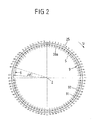
- the FIG. 2 shows a first embodiment of a circumferential asymmetry, which has the inside annular space surface of a peripheral housing 25.
- the peripheral housing 25 is, for example, the peripheral housing 25 of FIG. 1 .
- the FIG. 2 shows the peripheral housing 25 in a front-to-rear view in the direction of the central axis 2 of the peripheral housing 25th
- a liner ring 9 is inserted on the inside.
- the insert ring 9 has - with respect to the viewing direction of FIG. 2 a front edge 91 and a rear edge 92. Since the insert ring 9 tapers conically towards the rear in the illustrated embodiment, the rear edge 92 has a smaller radial distance from the central axis 2 than the front edge 91.
- the insert ring 9 forms on its inner side facing the central axis 2 an annular space surface 26a which delimits the adjacent flow channel radially on the outside.
- the annular space surface is generally formed either by the inside of the housing itself or, if present, by the inside of a deposit ring or other internally mounted part.
- the insert ring 9 has, apart from a circumferentially extending portion U 6, a symmetrical structuring of the annular space surface 26a, which is provided by a plurality, in the illustrated embodiment by seventy-eight recesses 5, which structure the annular space surface 26a at regular intervals in the circumferential direction.
- the recesses 5 each extend in the axial direction and have a length which substantially corresponds to the width of the rotor blades of the associated rotor, not shown.
- the circumferentially symmetrical housing structuring extends along an axial region of the peripheral housing which peripherally adjoins the associated rotor and which corresponds essentially to the axial extent of the blade lattice of the rotor.
- the axial recesses 5 may also have a different length, for example, may be made shorter, so that they correspond to only a fraction of the axial length of the blade grid of the associated rotor, or may be formed longer, so that they in Areas of the Circumferential housing or the insert ring extending, which are located in front of and / or behind the respective blade grid.
- the axially extending recesses 5 are generated, for example, by internal milling or erosion of the insert ring 9. They can form axial grooves or pockets.
- structuring according to the recesses 5, if no insert ring 9 is present, can alternatively also be produced on the housing wall of the housing 25 itself.
- illustrated symmetrical structuring by axial recesses 5 does not extend along the entire circumference of the annular space surface 26a. Rather, a break in symmetry in the form of extending in the circumferential direction U section 6 is provided in which the annular space surface 26 a smooth, that is formed without axial recesses 5. Outside the section 6, the annular space surface 26a is thus structured circumferentially symmetrical, but not in the section 6. The section 6 extends over a defined circumferential angle .DELTA..phi.
- the structuring of the annular space surface as a whole is without circumferential symmetry, since the structuring can be completely imaged onto itself solely by a rotation through an angle of 360 °.
- FIG. 2 shown circumferential asymmetry can undergo numerous modifications.
- a plurality of sections 6 may be provided, in which the annular space surface 26a is not structured.
- Such portions 6 would be asymmetrically distributed over the circumference, so that the structuring in turn can be imaged on itself only by a rotation through an angle of 360 °.
- the symmetrical structuring provided by the axial recesses 5 also extends into the section 6, wherein, however, an additional circumferentially asymmetric structuring is provided in the section 6, for example a depression in which then the axial Recesses 5 are formed.
- an additional circumferentially asymmetric structuring is provided in the section 6, for example a depression in which then the axial Recesses 5 are formed.
- a symmetrical structuring in the circumferential direction would be superimposed on an asymmetrical structuring in the circumferential direction.
- a further alternative embodiment provides that only a circumferentially extending section, corresponding to the section 6 of FIG. 2 has at all a structuring, while the annular space surface 26a is formed smooth outside of this section. It would be a reversal of that in the FIG. 2 presented conditions.
- FIG. 3 shows a perspective view of the inside of a peripheral housing 25, for example, the peripheral housing 25 of FIG. 1 However, but also the peripheral housing 15 or the peripheral housing 55 of the FIG. 1 could be.
- the peripheral housing 25 forms on the inside an annular space surface 26, which the flow channel 3 (see. FIG. 1 ) bounded radially on the outside.
- a insert ring 9 ' is arranged on the inside of the peripheral housing 25, on the inside of the peripheral housing 25, a insert ring 9 'is arranged. Where the insert ring 9 'is arranged, its surface 26b facing the flow channel forms the annular space surface of the housing 25.
- the insert ring 9 ' is concave in a central region 93'. This concave configuration results from the fact that the insert ring 9 'is milled by the blades 22 of the associated rotor.
- the insert ring 9 ' consists of a comparatively soft material. Such provision of a liner ring 9 'is associated with the advantage of a small annular gap between the blade tip of the blades 22 and the annulus surface 26b.
- FIG. 4 equals to FIG. 3 , where in the FIG. 4 in addition blades 22 of the associated rotor are shown.
- a recess 7 is introduced. This is provided, for example, by eroding or milling the insert ring 9 '.
- the recess 7 may have elongated grooves 71; These arise during the production of the recess 7 and are optional. Outside the recess 7 of the insert ring 9 'is not structured, d. H. smooth running. The recess 7 therefore provides a circumferentially asymmetric structure of the annulus surface 26b.
- the recess 7 has an axial length x1, which is slightly larger than the axial extent of the portion 93 'of the insert ring 9', which circumferentially adjacent to the blades 22 of the associated rotor.
- the axial extension x1 of the recess 7 is thus slightly larger than the axial extent of the blade grid of the associated rotor. Alternatively, it may also be as large or smaller than the axial extent of the blade grid.
- the recess 7 further has a length u1 in the circumferential direction U, which corresponds to a circumferential angle ⁇ 1 of the associated circular sector.
- a plurality of recesses 7 may be formed along the circumference of the insert ring 9 ', wherein such a plurality of recesses are circumferentially arranged asymmetrically.
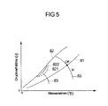
- FIG. 5 illustrates the advantages associated with the circumferentially asymmetric design of the annulus area benefits.
- the circumferentially asymmetric design of the annulus area reduces the vibration excitation of blades and thus an improvement in the flutter stability.
- the compressor pressure ratio is shown as a function of the mass flow.
- the reference numeral 81 indicates the working line and the point DP indicates a design point under consideration.
- Reference numeral 82 indicates the stability line, also referred to as the surge line.
- the map comprises lines 83 of constant speed N.
- a blade flutter results in a dip in the stability line 82, which in this case is replaced by the flutter line 821.
- the circumferentially asymmetric structuring according to the invention of the annular space surface results in that the indentation of the stability line 82 is reduced, so that the stability line 82 is replaced by the flutter line 822 in the case of annular space asymmetry.
- the distance between the flutter line 821 without annular space asymmetry and the flutter line 822 with annular space asymmetry clarifies the advantages associated with the annular space asymmetry according to the invention.
- the distance between an operating point 81 operating point to the stability line 82 is advantageously increased.
- the invention is not limited in its embodiment to the embodiments shown above, which are to be understood only as examples.
- structures may be provided that may be in other ways, shapes, and / or shapes are formed and arranged elsewhere than described in the embodiments.
Landscapes
- Engineering & Computer Science (AREA)
- Mechanical Engineering (AREA)
- General Engineering & Computer Science (AREA)
- Structures Of Non-Positive Displacement Pumps (AREA)
Applications Claiming Priority (1)
| Application Number | Priority Date | Filing Date | Title |
|---|---|---|---|
| DE102011007767A DE102011007767A1 (de) | 2011-04-20 | 2011-04-20 | Strömungsmaschine |
Publications (3)
| Publication Number | Publication Date |
|---|---|
| EP2514975A2 true EP2514975A2 (fr) | 2012-10-24 |
| EP2514975A3 EP2514975A3 (fr) | 2014-06-11 |
| EP2514975B1 EP2514975B1 (fr) | 2017-08-02 |
Family
ID=46000967
Family Applications (1)
| Application Number | Title | Priority Date | Filing Date |
|---|---|---|---|
| EP12164964.4A Active EP2514975B1 (fr) | 2011-04-20 | 2012-04-20 | Turbomachine |
Country Status (3)
| Country | Link |
|---|---|
| US (1) | US9816528B2 (fr) |
| EP (1) | EP2514975B1 (fr) |
| DE (1) | DE102011007767A1 (fr) |
Cited By (1)
| Publication number | Priority date | Publication date | Assignee | Title |
|---|---|---|---|---|
| EP3591237A1 (fr) * | 2018-07-03 | 2020-01-08 | Rolls-Royce Deutschland Ltd & Co KG | Module structural pour un compresseur d'une turbomachine |
Families Citing this family (12)
| Publication number | Priority date | Publication date | Assignee | Title |
|---|---|---|---|---|
| US9267386B2 (en) | 2012-06-29 | 2016-02-23 | United Technologies Corporation | Fairing assembly |
| US10344601B2 (en) | 2012-08-17 | 2019-07-09 | United Technologies Corporation | Contoured flowpath surface |
| US10344711B2 (en) * | 2016-01-11 | 2019-07-09 | Rolls-Royce Corporation | System and method of alleviating blade flutter |
| US10465539B2 (en) * | 2017-08-04 | 2019-11-05 | Pratt & Whitney Canada Corp. | Rotor casing |
| CN116464675B (zh) * | 2023-06-20 | 2023-09-01 | 河北拓顺医疗科技有限公司 | 一种呼吸机内置风机用减震型降噪装置 |
| US12359584B1 (en) * | 2024-01-03 | 2025-07-15 | Honeywell International Inc. | Acoustic engine casing for gas turbine engine |
| US12258870B1 (en) | 2024-03-08 | 2025-03-25 | Rolls-Royce North American Technologies Inc. | Adjustable fan track liner with slotted array active fan tip treatment for distortion tolerance |
| US12286936B1 (en) | 2024-05-09 | 2025-04-29 | Rolls-Royce North American Technologies Inc. | Adjustable fan track liner with groove array active fan tip treatment for distortion tolerance |
| US12209541B1 (en) | 2024-05-09 | 2025-01-28 | Rolls-Royce North American Technologies Inc. | Adjustable fan track liner with dual slotted array active fan tip treatment for distortion tolerance |
| US12215712B1 (en) | 2024-05-09 | 2025-02-04 | Rolls-Royce North American Technologies Inc. | Adjustable fan track liner with dual grooved array active fan tip treatment for distortion tolerance |
| US12168983B1 (en) | 2024-06-28 | 2024-12-17 | Rolls-Royce North American Technologies Inc. | Active fan tip treatment using rotating drum array in fan track liner with axial and circumferential channels for distortion tolerance |
| US12209502B1 (en) | 2024-06-28 | 2025-01-28 | Rolls-Royce North American Technologies Inc. | Active fan tip treatment using rotating drum array with axial channels in fan track liner for distortion tolerance |
Citations (1)
| Publication number | Priority date | Publication date | Assignee | Title |
|---|---|---|---|---|
| DE102007056953A1 (de) | 2007-11-27 | 2009-05-28 | Rolls-Royce Deutschland Ltd & Co Kg | Strömungsarbeitsmaschine mit Ringkanalwandausnehmung |
Family Cites Families (45)
| Publication number | Priority date | Publication date | Assignee | Title |
|---|---|---|---|---|
| US3890060A (en) * | 1974-02-15 | 1975-06-17 | Gen Electric | Acoustic duct with asymmetric acoustical treatment |
| JPS6318799Y2 (fr) * | 1980-12-02 | 1988-05-26 | ||
| GB2090334B (en) * | 1980-12-29 | 1983-11-16 | Rolls Royce | Damping flutter of ducted fans |
| GB2245312B (en) | 1984-06-19 | 1992-03-25 | Rolls Royce Plc | Axial flow compressor surge margin improvement |
| CA1314486C (fr) * | 1984-06-19 | 1993-03-16 | Michael John Charles Waterman | Methode d'amelioration de la reserve de pompage d'un compresseur a flux axial |
| US5067876A (en) | 1990-03-29 | 1991-11-26 | General Electric Company | Gas turbine bladed disk |
| GB2281356B (en) | 1993-08-20 | 1997-01-29 | Rolls Royce Plc | Gas turbine engine turbine |
| EP0774050B1 (fr) * | 1994-06-14 | 1999-03-10 | United Technologies Corporation | Structure de stator a rainures circonferentielles interrompues |
| US5562404A (en) | 1994-12-23 | 1996-10-08 | United Technologies Corporation | Vaned passage hub treatment for cantilever stator vanes |
| US5725353A (en) | 1996-12-04 | 1998-03-10 | United Technologies Corporation | Turbine engine rotor disk |
| DE19650656C1 (de) | 1996-12-06 | 1998-06-10 | Mtu Muenchen Gmbh | Turbomaschine mit transsonischer Verdichterstufe |
| GB9823840D0 (en) | 1998-10-30 | 1998-12-23 | Rolls Royce Plc | Bladed ducting for turbomachinery |
| US6290458B1 (en) * | 1999-09-20 | 2001-09-18 | Hitachi, Ltd. | Turbo machines |
| US6511294B1 (en) | 1999-09-23 | 2003-01-28 | General Electric Company | Reduced-stress compressor blisk flowpath |
| US6561761B1 (en) | 2000-02-18 | 2003-05-13 | General Electric Company | Fluted compressor flowpath |
| US6471474B1 (en) | 2000-10-20 | 2002-10-29 | General Electric Company | Method and apparatus for reducing rotor assembly circumferential rim stress |
| US6409469B1 (en) * | 2000-11-21 | 2002-06-25 | Pratt & Whitney Canada Corp. | Fan-stator interaction tone reduction |
| US6478545B2 (en) | 2001-03-07 | 2002-11-12 | General Electric Company | Fluted blisk |
| JP3872966B2 (ja) * | 2001-06-29 | 2007-01-24 | 株式会社日立プラントテクノロジー | 軸流形流体機械 |
| US6969232B2 (en) | 2002-10-23 | 2005-11-29 | United Technologies Corporation | Flow directing device |
| GB2408546B (en) * | 2003-11-25 | 2006-02-22 | Rolls Royce Plc | A compressor having casing treatment slots |
| US7690890B2 (en) | 2004-09-24 | 2010-04-06 | Ishikawajima-Harima Heavy Industries Co. Ltd. | Wall configuration of axial-flow machine, and gas turbine engine |
| US7134842B2 (en) | 2004-12-24 | 2006-11-14 | General Electric Company | Scalloped surface turbine stage |
| US7220100B2 (en) | 2005-04-14 | 2007-05-22 | General Electric Company | Crescentic ramp turbine stage |
| GB0518628D0 (en) | 2005-09-13 | 2005-10-19 | Rolls Royce Plc | Axial compressor blading |
| US7861823B2 (en) * | 2005-11-04 | 2011-01-04 | United Technologies Corporation | Duct for reducing shock related noise |
| GB0600532D0 (en) * | 2006-01-12 | 2006-02-22 | Rolls Royce Plc | A blade and rotor arrangement |
| US7465155B2 (en) | 2006-02-27 | 2008-12-16 | Honeywell International Inc. | Non-axisymmetric end wall contouring for a turbomachine blade row |
| US7874794B2 (en) | 2006-03-21 | 2011-01-25 | General Electric Company | Blade row for a rotary machine and method of fabricating same |
| US7887297B2 (en) | 2006-05-02 | 2011-02-15 | United Technologies Corporation | Airfoil array with an endwall protrusion and components of the array |
| US7909570B2 (en) | 2006-08-25 | 2011-03-22 | Pratt & Whitney Canada Corp. | Interturbine duct with integrated baffle and seal |
| DE102006048933A1 (de) * | 2006-10-17 | 2008-04-24 | Mtu Aero Engines Gmbh | Anordnung zur Strömungsbeeinflussung |
| FR2912789B1 (fr) * | 2007-02-21 | 2009-10-02 | Snecma Sa | Carter avec traitement de carter, compresseur et turbomachine comportant un tel carter. |
| JP5283855B2 (ja) | 2007-03-29 | 2013-09-04 | 株式会社Ihi | ターボ機械の壁、及びターボ機械 |
| DE102007020025A1 (de) | 2007-04-27 | 2008-10-30 | Honda Motor Co., Ltd. | Form eines Gaskanals in einer Axialströmungs-Gasturbinenmaschine |
| JP4400686B2 (ja) | 2008-01-07 | 2010-01-20 | ダイキン工業株式会社 | プロペラファン |
| FR2928174B1 (fr) | 2008-02-28 | 2011-05-06 | Snecma | Aube avec plateforme non axisymetrique : creux et bosse sur extrados. |
| DE102008011644A1 (de) | 2008-02-28 | 2009-09-03 | Rolls-Royce Deutschland Ltd & Co Kg | Gehäusestrukturierung für Axialverdichter im Nabenbereich |
| DE102008021053A1 (de) | 2008-04-26 | 2009-10-29 | Mtu Aero Engines Gmbh | Nachgeformter Strömungspfad einer Axialströmungsmaschine zur Verringerung von Sekundärströmung |
| DE102008031982A1 (de) * | 2008-07-07 | 2010-01-14 | Rolls-Royce Deutschland Ltd & Co Kg | Strömungsarbeitsmaschine mit Nut an einem Laufspalt eines Schaufelendes |
| DE102008052401A1 (de) | 2008-10-21 | 2010-04-22 | Rolls-Royce Deutschland Ltd & Co Kg | Strömungsarbeitsmaschine mit Laufspalteinzug |
| US8439643B2 (en) | 2009-08-20 | 2013-05-14 | General Electric Company | Biformal platform turbine blade |
| FR2950942B1 (fr) | 2009-10-02 | 2013-08-02 | Snecma | Rotor d'un compresseur de turbomachine a paroi d'extremite interne optimisee |
| US8684684B2 (en) | 2010-08-31 | 2014-04-01 | General Electric Company | Turbine assembly with end-wall-contoured airfoils and preferenttial clocking |
| US8678740B2 (en) * | 2011-02-07 | 2014-03-25 | United Technologies Corporation | Turbomachine flow path having circumferentially varying outer periphery |
-
2011
- 2011-04-20 DE DE102011007767A patent/DE102011007767A1/de not_active Withdrawn
-
2012
- 2012-04-20 EP EP12164964.4A patent/EP2514975B1/fr active Active
- 2012-04-20 US US13/451,657 patent/US9816528B2/en active Active
Patent Citations (1)
| Publication number | Priority date | Publication date | Assignee | Title |
|---|---|---|---|---|
| DE102007056953A1 (de) | 2007-11-27 | 2009-05-28 | Rolls-Royce Deutschland Ltd & Co Kg | Strömungsarbeitsmaschine mit Ringkanalwandausnehmung |
Cited By (2)
| Publication number | Priority date | Publication date | Assignee | Title |
|---|---|---|---|---|
| EP3591237A1 (fr) * | 2018-07-03 | 2020-01-08 | Rolls-Royce Deutschland Ltd & Co KG | Module structural pour un compresseur d'une turbomachine |
| US11131322B2 (en) | 2018-07-03 | 2021-09-28 | Rolls-Royce Deutschland Ltd & Co Kg | Structural assembly for a compressor of a fluid flow machine |
Also Published As
| Publication number | Publication date |
|---|---|
| US9816528B2 (en) | 2017-11-14 |
| EP2514975B1 (fr) | 2017-08-02 |
| DE102011007767A1 (de) | 2012-10-25 |
| EP2514975A3 (fr) | 2014-06-11 |
| US20120269619A1 (en) | 2012-10-25 |
Similar Documents
| Publication | Publication Date | Title |
|---|---|---|
| EP2514975B1 (fr) | Turbomachine | |
| EP2242931B1 (fr) | Structure d'écoulement pour turbocompresseur | |
| EP2025945B1 (fr) | Machine de traitement des écoulements dotée d'un creux de paroi de canal de ceinture | |
| DE102011054589B4 (de) | Rotationsmaschine mit Abstandhaltern zur Steuerung der Fluiddynamik | |
| EP2761137B1 (fr) | Pale d'une rangée de pales de rotor ou de stator pour une turbomachine | |
| EP3428393B1 (fr) | Roue aubagée d'une turbomachine | |
| EP2014925A1 (fr) | Diffuseur pour compresseur radial | |
| EP2921716B1 (fr) | Groupe de série d'aubes | |
| DE102013109203A1 (de) | Wirbelunterbrechende Dichtungszähne für eine Dichtungsanordnung | |
| DE102014219821A1 (de) | Rückführstufe | |
| EP3161325A1 (fr) | Diffuseur pour compresseur radial | |
| EP3236011B1 (fr) | Rotor comprenant un porte à faux sur les pales pour un élément de sécurité | |
| EP2647796A1 (fr) | Système d'étanchéité pour turbomachine | |
| EP2913481B1 (fr) | Aubes en tandem d'une turbomachine | |
| EP3650709A1 (fr) | Dispositif diffuseur à aubes pour un compresseur radial | |
| EP2921715A1 (fr) | Groupe de série d'aubes | |
| EP1953340B1 (fr) | Machine de traitement des écoulements et aube de rotor d'une machine de traitement des écoulements | |
| EP3309359A1 (fr) | Ensemble d'aubes mobiles pour un moteur à turbine à gaz | |
| EP3406860B1 (fr) | Turboréacteur | |
| DE102016219818A1 (de) | Laufschaufelbaugruppe mit ringsegment- oder scheibensegmentförmigem Schaufelträger und radial innenliegender Versteifungsstruktur | |
| EP3225789A1 (fr) | Ensemble de moteur avec carter de soufflante et diffuseur d'entrée | |
| EP1711689B1 (fr) | Ensemble d' étanchéité | |
| EP3404211A1 (fr) | Segment de grille d'aubes d'une turbine avec paroi de plateforme contourée, grille d'aubes, canal d'aube, plateforme, turbine et moteur d'aéronef associés | |
| EP3315720A2 (fr) | Rotor de compresseur d'une turbomachine | |
| DE102019213932B4 (de) | Verdichterstufe mit variabler Statorschaufelneigung |
Legal Events
| Date | Code | Title | Description |
|---|---|---|---|
| PUAI | Public reference made under article 153(3) epc to a published international application that has entered the european phase |
Free format text: ORIGINAL CODE: 0009012 |
|
| AK | Designated contracting states |
Kind code of ref document: A2 Designated state(s): AL AT BE BG CH CY CZ DE DK EE ES FI FR GB GR HR HU IE IS IT LI LT LU LV MC MK MT NL NO PL PT RO RS SE SI SK SM TR |
|
| AX | Request for extension of the european patent |
Extension state: BA ME |
|
| PUAL | Search report despatched |
Free format text: ORIGINAL CODE: 0009013 |
|
| AK | Designated contracting states |
Kind code of ref document: A3 Designated state(s): AL AT BE BG CH CY CZ DE DK EE ES FI FR GB GR HR HU IE IS IT LI LT LU LV MC MK MT NL NO PL PT RO RS SE SI SK SM TR |
|
| AX | Request for extension of the european patent |
Extension state: BA ME |
|
| RIC1 | Information provided on ipc code assigned before grant |
Ipc: F04D 29/68 20060101ALI20140506BHEP Ipc: F04D 29/52 20060101ALI20140506BHEP Ipc: F04D 29/16 20060101ALI20140506BHEP Ipc: F04D 29/66 20060101AFI20140506BHEP Ipc: F01D 25/04 20060101ALI20140506BHEP |
|
| 17P | Request for examination filed |
Effective date: 20141210 |
|
| RBV | Designated contracting states (corrected) |
Designated state(s): AL AT BE BG CH CY CZ DE DK EE ES FI FR GB GR HR HU IE IS IT LI LT LU LV MC MK MT NL NO PL PT RO RS SE SI SK SM TR |
|
| 17Q | First examination report despatched |
Effective date: 20151026 |
|
| GRAP | Despatch of communication of intention to grant a patent |
Free format text: ORIGINAL CODE: EPIDOSNIGR1 |
|
| INTG | Intention to grant announced |
Effective date: 20170313 |
|
| RIN1 | Information on inventor provided before grant (corrected) |
Inventor name: JOHANN, ERIK |
|
| GRAS | Grant fee paid |
Free format text: ORIGINAL CODE: EPIDOSNIGR3 |
|
| GRAJ | Information related to disapproval of communication of intention to grant by the applicant or resumption of examination proceedings by the epo deleted |
Free format text: ORIGINAL CODE: EPIDOSDIGR1 |
|
| GRAL | Information related to payment of fee for publishing/printing deleted |
Free format text: ORIGINAL CODE: EPIDOSDIGR3 |
|
| GRAR | Information related to intention to grant a patent recorded |
Free format text: ORIGINAL CODE: EPIDOSNIGR71 |
|
| GRAA | (expected) grant |
Free format text: ORIGINAL CODE: 0009210 |
|
| INTC | Intention to grant announced (deleted) | ||
| AK | Designated contracting states |
Kind code of ref document: B1 Designated state(s): AL AT BE BG CH CY CZ DE DK EE ES FI FR GB GR HR HU IE IS IT LI LT LU LV MC MK MT NL NO PL PT RO RS SE SI SK SM TR |
|
| INTG | Intention to grant announced |
Effective date: 20170627 |
|
| REG | Reference to a national code |
Ref country code: GB Ref legal event code: FG4D Free format text: NOT ENGLISH |
|
| REG | Reference to a national code |
Ref country code: CH Ref legal event code: EP Ref country code: AT Ref legal event code: REF Ref document number: 914812 Country of ref document: AT Kind code of ref document: T Effective date: 20170815 |
|
| REG | Reference to a national code |
Ref country code: IE Ref legal event code: FG4D Free format text: LANGUAGE OF EP DOCUMENT: GERMAN |
|
| REG | Reference to a national code |
Ref country code: DE Ref legal event code: R096 Ref document number: 502012010889 Country of ref document: DE |
|
| REG | Reference to a national code |
Ref country code: NL Ref legal event code: MP Effective date: 20170802 |
|
| REG | Reference to a national code |
Ref country code: LT Ref legal event code: MG4D |
|
| PG25 | Lapsed in a contracting state [announced via postgrant information from national office to epo] |
Ref country code: NO Free format text: LAPSE BECAUSE OF FAILURE TO SUBMIT A TRANSLATION OF THE DESCRIPTION OR TO PAY THE FEE WITHIN THE PRESCRIBED TIME-LIMIT Effective date: 20171102 Ref country code: FI Free format text: LAPSE BECAUSE OF FAILURE TO SUBMIT A TRANSLATION OF THE DESCRIPTION OR TO PAY THE FEE WITHIN THE PRESCRIBED TIME-LIMIT Effective date: 20170802 Ref country code: NL Free format text: LAPSE BECAUSE OF FAILURE TO SUBMIT A TRANSLATION OF THE DESCRIPTION OR TO PAY THE FEE WITHIN THE PRESCRIBED TIME-LIMIT Effective date: 20170802 Ref country code: HR Free format text: LAPSE BECAUSE OF FAILURE TO SUBMIT A TRANSLATION OF THE DESCRIPTION OR TO PAY THE FEE WITHIN THE PRESCRIBED TIME-LIMIT Effective date: 20170802 Ref country code: LT Free format text: LAPSE BECAUSE OF FAILURE TO SUBMIT A TRANSLATION OF THE DESCRIPTION OR TO PAY THE FEE WITHIN THE PRESCRIBED TIME-LIMIT Effective date: 20170802 Ref country code: SE Free format text: LAPSE BECAUSE OF FAILURE TO SUBMIT A TRANSLATION OF THE DESCRIPTION OR TO PAY THE FEE WITHIN THE PRESCRIBED TIME-LIMIT Effective date: 20170802 |
|
| PG25 | Lapsed in a contracting state [announced via postgrant information from national office to epo] |
Ref country code: LV Free format text: LAPSE BECAUSE OF FAILURE TO SUBMIT A TRANSLATION OF THE DESCRIPTION OR TO PAY THE FEE WITHIN THE PRESCRIBED TIME-LIMIT Effective date: 20170802 Ref country code: BG Free format text: LAPSE BECAUSE OF FAILURE TO SUBMIT A TRANSLATION OF THE DESCRIPTION OR TO PAY THE FEE WITHIN THE PRESCRIBED TIME-LIMIT Effective date: 20171102 Ref country code: IS Free format text: LAPSE BECAUSE OF FAILURE TO SUBMIT A TRANSLATION OF THE DESCRIPTION OR TO PAY THE FEE WITHIN THE PRESCRIBED TIME-LIMIT Effective date: 20171202 Ref country code: RS Free format text: LAPSE BECAUSE OF FAILURE TO SUBMIT A TRANSLATION OF THE DESCRIPTION OR TO PAY THE FEE WITHIN THE PRESCRIBED TIME-LIMIT Effective date: 20170802 Ref country code: GR Free format text: LAPSE BECAUSE OF FAILURE TO SUBMIT A TRANSLATION OF THE DESCRIPTION OR TO PAY THE FEE WITHIN THE PRESCRIBED TIME-LIMIT Effective date: 20171103 Ref country code: ES Free format text: LAPSE BECAUSE OF FAILURE TO SUBMIT A TRANSLATION OF THE DESCRIPTION OR TO PAY THE FEE WITHIN THE PRESCRIBED TIME-LIMIT Effective date: 20170802 Ref country code: PL Free format text: LAPSE BECAUSE OF FAILURE TO SUBMIT A TRANSLATION OF THE DESCRIPTION OR TO PAY THE FEE WITHIN THE PRESCRIBED TIME-LIMIT Effective date: 20170802 |
|
| REG | Reference to a national code |
Ref country code: FR Ref legal event code: PLFP Year of fee payment: 7 |
|
| PG25 | Lapsed in a contracting state [announced via postgrant information from national office to epo] |
Ref country code: RO Free format text: LAPSE BECAUSE OF FAILURE TO SUBMIT A TRANSLATION OF THE DESCRIPTION OR TO PAY THE FEE WITHIN THE PRESCRIBED TIME-LIMIT Effective date: 20170802 Ref country code: CZ Free format text: LAPSE BECAUSE OF FAILURE TO SUBMIT A TRANSLATION OF THE DESCRIPTION OR TO PAY THE FEE WITHIN THE PRESCRIBED TIME-LIMIT Effective date: 20170802 Ref country code: DK Free format text: LAPSE BECAUSE OF FAILURE TO SUBMIT A TRANSLATION OF THE DESCRIPTION OR TO PAY THE FEE WITHIN THE PRESCRIBED TIME-LIMIT Effective date: 20170802 |
|
| REG | Reference to a national code |
Ref country code: DE Ref legal event code: R097 Ref document number: 502012010889 Country of ref document: DE |
|
| PG25 | Lapsed in a contracting state [announced via postgrant information from national office to epo] |
Ref country code: SM Free format text: LAPSE BECAUSE OF FAILURE TO SUBMIT A TRANSLATION OF THE DESCRIPTION OR TO PAY THE FEE WITHIN THE PRESCRIBED TIME-LIMIT Effective date: 20170802 Ref country code: IT Free format text: LAPSE BECAUSE OF FAILURE TO SUBMIT A TRANSLATION OF THE DESCRIPTION OR TO PAY THE FEE WITHIN THE PRESCRIBED TIME-LIMIT Effective date: 20170802 Ref country code: EE Free format text: LAPSE BECAUSE OF FAILURE TO SUBMIT A TRANSLATION OF THE DESCRIPTION OR TO PAY THE FEE WITHIN THE PRESCRIBED TIME-LIMIT Effective date: 20170802 Ref country code: SK Free format text: LAPSE BECAUSE OF FAILURE TO SUBMIT A TRANSLATION OF THE DESCRIPTION OR TO PAY THE FEE WITHIN THE PRESCRIBED TIME-LIMIT Effective date: 20170802 |
|
| PLBE | No opposition filed within time limit |
Free format text: ORIGINAL CODE: 0009261 |
|
| STAA | Information on the status of an ep patent application or granted ep patent |
Free format text: STATUS: NO OPPOSITION FILED WITHIN TIME LIMIT |
|
| 26N | No opposition filed |
Effective date: 20180503 |
|
| PG25 | Lapsed in a contracting state [announced via postgrant information from national office to epo] |
Ref country code: SI Free format text: LAPSE BECAUSE OF FAILURE TO SUBMIT A TRANSLATION OF THE DESCRIPTION OR TO PAY THE FEE WITHIN THE PRESCRIBED TIME-LIMIT Effective date: 20170802 |
|
| PG25 | Lapsed in a contracting state [announced via postgrant information from national office to epo] |
Ref country code: MT Free format text: LAPSE BECAUSE OF FAILURE TO SUBMIT A TRANSLATION OF THE DESCRIPTION OR TO PAY THE FEE WITHIN THE PRESCRIBED TIME-LIMIT Effective date: 20170802 |
|
| PG25 | Lapsed in a contracting state [announced via postgrant information from national office to epo] |
Ref country code: MC Free format text: LAPSE BECAUSE OF FAILURE TO SUBMIT A TRANSLATION OF THE DESCRIPTION OR TO PAY THE FEE WITHIN THE PRESCRIBED TIME-LIMIT Effective date: 20170802 |
|
| REG | Reference to a national code |
Ref country code: CH Ref legal event code: PL |
|
| REG | Reference to a national code |
Ref country code: BE Ref legal event code: MM Effective date: 20180430 |
|
| REG | Reference to a national code |
Ref country code: IE Ref legal event code: MM4A |
|
| PG25 | Lapsed in a contracting state [announced via postgrant information from national office to epo] |
Ref country code: LU Free format text: LAPSE BECAUSE OF NON-PAYMENT OF DUE FEES Effective date: 20180420 |
|
| PG25 | Lapsed in a contracting state [announced via postgrant information from national office to epo] |
Ref country code: CH Free format text: LAPSE BECAUSE OF NON-PAYMENT OF DUE FEES Effective date: 20180430 Ref country code: LI Free format text: LAPSE BECAUSE OF NON-PAYMENT OF DUE FEES Effective date: 20180430 Ref country code: BE Free format text: LAPSE BECAUSE OF NON-PAYMENT OF DUE FEES Effective date: 20180430 |
|
| PG25 | Lapsed in a contracting state [announced via postgrant information from national office to epo] |
Ref country code: IE Free format text: LAPSE BECAUSE OF NON-PAYMENT OF DUE FEES Effective date: 20180420 |
|
| REG | Reference to a national code |
Ref country code: AT Ref legal event code: MM01 Ref document number: 914812 Country of ref document: AT Kind code of ref document: T Effective date: 20180420 |
|
| PG25 | Lapsed in a contracting state [announced via postgrant information from national office to epo] |
Ref country code: AT Free format text: LAPSE BECAUSE OF NON-PAYMENT OF DUE FEES Effective date: 20180420 |
|
| PG25 | Lapsed in a contracting state [announced via postgrant information from national office to epo] |
Ref country code: TR Free format text: LAPSE BECAUSE OF FAILURE TO SUBMIT A TRANSLATION OF THE DESCRIPTION OR TO PAY THE FEE WITHIN THE PRESCRIBED TIME-LIMIT Effective date: 20170802 |
|
| PG25 | Lapsed in a contracting state [announced via postgrant information from national office to epo] |
Ref country code: HU Free format text: LAPSE BECAUSE OF FAILURE TO SUBMIT A TRANSLATION OF THE DESCRIPTION OR TO PAY THE FEE WITHIN THE PRESCRIBED TIME-LIMIT; INVALID AB INITIO Effective date: 20120420 Ref country code: PT Free format text: LAPSE BECAUSE OF FAILURE TO SUBMIT A TRANSLATION OF THE DESCRIPTION OR TO PAY THE FEE WITHIN THE PRESCRIBED TIME-LIMIT Effective date: 20170802 |
|
| PG25 | Lapsed in a contracting state [announced via postgrant information from national office to epo] |
Ref country code: MK Free format text: LAPSE BECAUSE OF NON-PAYMENT OF DUE FEES Effective date: 20170802 Ref country code: CY Free format text: LAPSE BECAUSE OF FAILURE TO SUBMIT A TRANSLATION OF THE DESCRIPTION OR TO PAY THE FEE WITHIN THE PRESCRIBED TIME-LIMIT Effective date: 20170802 |
|
| PG25 | Lapsed in a contracting state [announced via postgrant information from national office to epo] |
Ref country code: AL Free format text: LAPSE BECAUSE OF FAILURE TO SUBMIT A TRANSLATION OF THE DESCRIPTION OR TO PAY THE FEE WITHIN THE PRESCRIBED TIME-LIMIT Effective date: 20170802 |
|
| PGFP | Annual fee paid to national office [announced via postgrant information from national office to epo] |
Ref country code: GB Payment date: 20200429 Year of fee payment: 9 |
|
| GBPC | Gb: european patent ceased through non-payment of renewal fee |
Effective date: 20210420 |
|
| PG25 | Lapsed in a contracting state [announced via postgrant information from national office to epo] |
Ref country code: GB Free format text: LAPSE BECAUSE OF NON-PAYMENT OF DUE FEES Effective date: 20210420 |
|
| P01 | Opt-out of the competence of the unified patent court (upc) registered |
Effective date: 20230528 |
|
| PGFP | Annual fee paid to national office [announced via postgrant information from national office to epo] |
Ref country code: DE Payment date: 20250428 Year of fee payment: 14 |
|
| PGFP | Annual fee paid to national office [announced via postgrant information from national office to epo] |
Ref country code: FR Payment date: 20250424 Year of fee payment: 14 |