EP3404211A1 - Segment de grille d'aubes d'une turbine avec paroi de plateforme contourée, grille d'aubes, canal d'aube, plateforme, turbine et moteur d'aéronef associés - Google Patents
Segment de grille d'aubes d'une turbine avec paroi de plateforme contourée, grille d'aubes, canal d'aube, plateforme, turbine et moteur d'aéronef associés Download PDFInfo
- Publication number
- EP3404211A1 EP3404211A1 EP17171145.0A EP17171145A EP3404211A1 EP 3404211 A1 EP3404211 A1 EP 3404211A1 EP 17171145 A EP17171145 A EP 17171145A EP 3404211 A1 EP3404211 A1 EP 3404211A1
- Authority
- EP
- European Patent Office
- Prior art keywords
- blade
- platform
- segment
- airfoil
- turbine
- Prior art date
- Legal status (The legal status is an assumption and is not a legal conclusion. Google has not performed a legal analysis and makes no representation as to the accuracy of the status listed.)
- Withdrawn
Links
- 238000011144 upstream manufacturing Methods 0.000 claims description 22
- 230000015572 biosynthetic process Effects 0.000 description 2
- 239000012530 fluid Substances 0.000 description 2
- 238000005755 formation reaction Methods 0.000 description 2
- 150000001875 compounds Chemical class 0.000 description 1
- 238000006073 displacement reaction Methods 0.000 description 1
- 238000000034 method Methods 0.000 description 1
- 238000000926 separation method Methods 0.000 description 1
- 230000003068 static effect Effects 0.000 description 1
Images


Classifications
-
- F—MECHANICAL ENGINEERING; LIGHTING; HEATING; WEAPONS; BLASTING
- F01—MACHINES OR ENGINES IN GENERAL; ENGINE PLANTS IN GENERAL; STEAM ENGINES
- F01D—NON-POSITIVE DISPLACEMENT MACHINES OR ENGINES, e.g. STEAM TURBINES
- F01D5/00—Blades; Blade-carrying members; Heating, heat-insulating, cooling or antivibration means on the blades or the members
- F01D5/12—Blades
- F01D5/14—Form or construction
- F01D5/141—Shape, i.e. outer, aerodynamic form
- F01D5/142—Shape, i.e. outer, aerodynamic form of the blades of successive rotor or stator blade-rows
- F01D5/143—Contour of the outer or inner working fluid flow path wall, i.e. shroud or hub contour
-
- Y—GENERAL TAGGING OF NEW TECHNOLOGICAL DEVELOPMENTS; GENERAL TAGGING OF CROSS-SECTIONAL TECHNOLOGIES SPANNING OVER SEVERAL SECTIONS OF THE IPC; TECHNICAL SUBJECTS COVERED BY FORMER USPC CROSS-REFERENCE ART COLLECTIONS [XRACs] AND DIGESTS
- Y02—TECHNOLOGIES OR APPLICATIONS FOR MITIGATION OR ADAPTATION AGAINST CLIMATE CHANGE
- Y02T—CLIMATE CHANGE MITIGATION TECHNOLOGIES RELATED TO TRANSPORTATION
- Y02T50/00—Aeronautics or air transport
- Y02T50/60—Efficient propulsion technologies, e.g. for aircraft
Definitions
- the present invention relates to a blade grid segment, a blade grid, a platform for a blade grid segment, a blade channel of a turbomachine, a turbine and an aircraft engine.
- a turbine (which in this document is not a turbomachine as a whole, but rather an expander, which is or is downstream of a compressor in a turbomachine) has (in particular in the region of a low-pressure turbine) regularly a flow channel for the passage of a fluid ,
- the flow channel which is also referred to as “annulus” is bounded radially inwardly by radially inner side walls and radially outwardly by radially outer side walls; the terms "radial” as well as “axial” and “circumferential direction” and terms derived therefrom are to be understood in this document - unless otherwise indicated - always with respect to an axis of rotation of the rotor.
- blade vanes In the annulus of a (low-pressure) turbine blade vanes are arranged (for which the term “blade ring” is common). They each include baffles and / or blades that are circumferentially spaced one behind the other at substantially regular intervals, and associated platforms, also referred to as “shrouds,” each having an upstream and a downstream platform edge. These platform edges limit the platform surface in the axial direction; In this document, the "surface of the platform” is the surface of the platform facing the blades (or blades).
- the edge of the platform which passes first through the annular space of the turbomachine (axial) main stream during operation, is referred to in this document "upstream” platform edge; as the “downstream” platform edge is called according to the other edge.
- the statements “downstream” and “upstream” respectively refer to the axial main flow direction and thereby only to the axial position, thus regardless of a possible displacement in the circumferential direction:
- a point in this document as “downstream of the leading edges” (or downstream of a other point) when compared to a direct connection of the leading edges (together) to the platform surface (or relative to the other point) axially in the mainstream direction (ie following her) is staggered;
- upstream with opposite direction.
- blade intermediate strip The portion of the platform surface which is bounded in the axial direction by the direct (ie in the circumferential direction without axial deviations) connections of the leading edges or the trailing edges of adjacent airfoils on the platform surface and in the circumferential direction through the suction side of the one and the pressure side of the other airfoil, is referred to in this document as "blade intermediate strip".
- the width of the blade intermediate strip in the circumferential direction is called the "pitch" of the blade grid. In particular, it can be measured as the distance of the leading edges of respectively adjacent blades in the circumferential direction in the region of the platform surface.
- the measured in the direction of the intended axial main flow distance of the leading edges of the blades from their trailing edges is called (axial) "grid width”.
- the pressure side of a blade and the suction side of an adjacent blade define in the circumferential direction in each case a so-called blade channel.
- a so-called blade channel In the radial direction of this blade channel is limited within the turbine by so-called side walls.
- side walls These are formed by radially inner, hub-side and / or radially outer, housing-side platforms.
- platform may refer to a radially inner and / or outer platform.
- a fluid flow guided through a flow channel is regularly influenced by the surfaces of the side walls. Flow layers that run close to these surfaces are deflected more strongly because of their lower velocity than laterally from the sidewalls flow layers. This creates a secondary flow, which is superimposed on an axial main flow and which leads in particular to eddies and pressure losses.
- contouring in the form of elevations and / or depressions is frequently introduced into the side walls.
- the object of the present invention is to provide a technique with which secondary flows in the annular space of a turbine can be reduced in an advantageous manner.
- An inventive blade grid segment is a segment of a blade grid for a turbine, especially for example for a low-pressure turbine. It includes a platform with a platform surface and at least two blades. Between the suction side of a first and the pressure side of the second of the airfoils, a blade intermediate strip is arranged on the platform surface, whose axial grid width is determined by the arrival and trailing edges of the airfoils.
- the platform surface has a ridge extending in a downstream half of the vane intermediate strip from the pressure side of the first to the suction side of the second one of the airfoils (i.e., the sides passing continuously from said pressure side to said suction side).
- a "sub-strip” is here referred to as the "downstream half” which extends by half the grid width upstream of the trailing edges of the blades (or a connection of these blades); In this sense, “halving” is thus axial expansion of the blade intermediate strip.
- a survey in this document is a local formation (such as a projection) in the platform surface to understand in which this extends to the side facing the blades.
- a “deepening” is (below) analogous to a local Forming in the platform surface in the other direction (ie the side facing away from the blades side) to understand (such as a sink or niche).
- elevation and “depression” are therefore based on an orientation or a coordinate system in which the airfoils and an elevation from the platform surface to " above “, ie radially inward in the case of a radially outer platform and radially outward in the case of a radially inner platform, extending and correspondingly leading a recess in the opposite direction (“down”).
- the bucket channel is thus regarded as lying “above” the platform surface
- a blade grid segment according to the invention may have one or more elevations with the above and / or below properties.
- the phrase "at least one" is sometimes omitted below for the sake of clarity.
- a vane grating segment according to the invention may be in one piece or assembled.
- the platform may be unitary or comprise two or more parts, each of which projects from one of the blades, or the platform may be formed as a separate component disposed between the blades.
- a platform according to the invention is adapted to abut in the circumferential direction on each side of an airfoil and with the blades (none, one or both of which can be integrally formed on the platform) together form an inventive blade grid segment according to one of the embodiments disclosed in this document ,
- a blade lattice according to the invention comprises at least one blade lattice segment according to the invention according to one of the embodiments disclosed in this document.
- An inventive blade channel leads through a blade grid segment according to the invention according to one of the embodiments disclosed in this document.
- the blade channel is delimited by the pressure side of one of the blade leaves of the blade grid segment and by the opposite suction side of the (adjacent) other of the blade leaves.
- the blade grid segment or the blade grid or the flow channel or the platform can in particular be part of a low-pressure turbine or be installed or used in a low-pressure turbine.
- the airfoils can be guide vanes or blades.
- the platform may be configured to limit a blade channel radially inwardly or radially outwardly through the blade grid segment.
- a turbine according to the invention comprises one or more vane grates according to the invention. Such can be arranged in particular in the region of a low-pressure turbine of the turbine.
- An aircraft engine according to the invention comprises a turbine according to the invention.
- the aircraft engine also has a compressor.
- An inventive blade grid segment, a blade grid according to the invention, a blade channel according to the invention, a platform according to the invention, a turbine according to the invention and an aircraft engine according to the invention influence the static pressure field on the platform surface and on the blades in the edge area due to the inventive geometry of the platform surface.
- a reduction of the secondary flow, in particular of vortices in the blade channel is made possible.
- losses can be reduced and the inflow into an optionally downstream lying further blade grid can be improved.
- the at least one elevation of the platform surface lies completely (ie, with each of its points) in the downstream half of the vane intermediate strip.
- the platform surface forms a curve or even a flat (eg, uncontoured) portion upstream of the bump which extends from the pressure side of the first to the suction side of the second airfoil, and preferably also within the downstream half of the airfoil forms a zero height line or a zero height surface in the sense that a survey is radially above (and possibly a depression radially below) of the zero height line or zero height surface.
- a bucket channel is considered to be "above" the platform surface.
- the first and / or the second blade in a section on the survey.
- a boundary line between the respective airfoil and the platform surface thus extends at least partially on the survey.
- Embodiments of the present invention have proved to be advantageous in which at least one highest point of the elevation is arranged in the circumferential direction in a middle region between the blade blades or in an environment of the first or the second blade blade.
- a distance of such a highest point of the elevation from the pressure side of the first airfoil can be between 40% and 60% of the pitch of the airfoil segment and / or at least one highest point of the elevation can be at most 25%, preferably at most 10%, of the pitch be spaced from the pressure side of the first airfoil.
- At least one highest point of the elevation may have a distance from the pressure side of the first airfoil which is at least 75%, preferably at least 90%, of the pitch (so that the highest point is located in an environment of the second airfoil The distance is to be understood in each case as measured in the circumferential direction (ie without a (non-zero) directional component in the axial direction).
- the "highest points” are understood to mean the points of the respective elevation in which these extend in the radial direction (in comparison with the other points of the elevation) furthest to the side, on which side wall or side wall opposite the platform Platform is arranged or to be arranged, so that therefore an associated blade channel is there locally maximally narrows.
- “deepest points” of a depression are those points in which the depression extends furthest to the other side (that is, away from a side where an opposite side wall or platform is located or disposed) in which one Shovel channel thus locally maximally extended.
- the highest and lowest points can form a curve or area (for example, if the elevation forms a ridge or ridge or a plateau, analogously for a depression) or be singular.
- the survey has exactly one highest point.
- the elevation may have at least one highest point lying on a boundary line between the platform surface and the pressure side of the first airfoil or on a boundary line between the platform surface and the suction side of the second airfoil.
- the platform surface may be convex or concave in each case.
- the platform surface except the survey on at least one depression has at least one lowest point which is arranged upstream of at least one highest point of the survey.
- a depression is arranged completely upstream of the at least one elevation (so that therefore each point of the depression is upstream compared to each point of the elevation).
- the recess may lie completely in an upstream half of the vane intermediate strip.
- the at least one depression may preferably extend into the blade intermediate strip by at most 60%, at most 40%, or even at most one third of the separation distance.
- the depression can be arranged in a third of the blade intermediate strip lying on the suction side of the second airfoil (which therefore extends in the circumferential direction from the suction side over one third of the pitch).
- a variant has proved to be advantageous in which a section of the second blade (on its suction side) is located in the recess of the platform surface (ie, at least part of a boundary line between the platform surface and the suction side is in the section in the recess, so that therefore the section of the suction side rises in particular from the depression).
- At least one deepest point of a depression is preferably in a (circumferentially measured) distance from the suction side of the second airfoil not greater than 10% of the pitch, or even on a boundary between the second airfoil and the platform surface.
- the elevation is a first elevation
- the platform surface has at least one second elevation that is located wholly or partially upstream of the first elevation.
- the second elevation may include at least one highest point located upstream of at least one highest point of the first elevation.
- such a second elevation extends preferably from the pressure side of the first airfoil at most 50% or even at most one third of the pitch in the blade intermediate strip. It may be limited, for example, by a zero height line (or even zero height surface) extending from a first location on the pressure side of the first airfoil to a second location of the pressure side, so that the second elevation between the pressure side and the zero height line (or area).
- An embodiment variant has proven to be advantageous in which a section of the first airfoil is based on its pressure side on the second elevation of the platform surface.
- At least one highest point of the second bump is preferably in a (circumferentially measured) distance from the pressure side of the first airfoil which is not greater than 10% of the pitch, or even on a boundary between the first airfoil and the platform surface.
- FIG. 2 schematically illustrates in plan view (with a radial viewing direction) an exemplary unwound embodiment of a vane segment 110 according to the invention. It comprises airfoils 20, 30, which each have a pressure side and a suction side, and a platform 10 according to the invention with a platform edge 10a (with respect to the intended axial main flow direction X) and a downstream platform edge 10b.
- the platform may be formed in one piece or, for example, in two parts (not shown), in particular it may comprise two parts, of which in each case one of the blades 20, 30 protrudes.
- a blade intermediate strip Z extends in the circumferential direction U from the pressure side 21 of a first airfoil 20 to the suction side 32 of the second airfoil 30.
- In the axial direction X of the blade intermediate strip Z upstream by a combination of the leading edges 23, 33 of the blades 20, 30 and downstream by a Connection of the respective trailing edges 24, 34 limited;
- the compounds run on the platform surface purely in the circumferential direction (ie without deviation in the axial direction), and they have a distance g from each other, which corresponds to the axial grid width g of the blade intermediate strip.
- a pitch t is defined as the distance of the leading edges 23, 33 from each other on the platform surface.
- the platform surface has a in the FIG. 1 Elevation 111 illustrated by contour lines has a highest point 112 which extends from the pressure side 21 of the first airfoil 20 to the suction side 32 of the second airfoil.
- the survey 111 is complete within a downstream half of the blade intermediate strip Z, that is to say in a partial strip which extends by half the axial grid width upstream of the trailing edges 24, 34 of the blades 20, 30.
- the elevation 111 is bounded by a curve 113, which also extends in the downstream half of the blade intermediate strip from the pressure side 21 of the first airfoil 20 to the suction side 32 of the second airfoil 30 and has a zero height.
- the area of the platform surface lying upstream of the curve 113 is preferably completely zero height area, in particular the platform surface is uncontoured in this example.
- both the first airfoil 20 at its pressure side 21 and the second airfoil 30 at its suction side 32 are located in a respective section on the elevation 111.
- Measured in the circumferential direction U has the highest point 112 of the survey 111 at the in FIG. 1 Blade segment 110 shown a distance D 1 from the pressure side 21 of the first blade 20, wherein D 1 ⁇ t / 10 applies.
- the distance is thus in this embodiment at most 10% of the pitch t. In other embodiments, this distance D 1 can also be at most 25% of the pitch t.
- a survey 121 has a in FIG. 2
- the highest point 122 has a distance D 2 from the pressure side 21 of the first blade.
- the highest point 122 has a distance D 2 from the pressure side 21 of the first blade. In this case, 0.4 t ⁇ D 2 ⁇ 0.6 t.
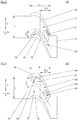
- FIG. 3 an embodiment of an inventive blade grid segment 130 is shown, in which the platform next to a survey 131 has a recess 132.
- the survey 131 is present as in FIG. 1 formed example and is therefore not described again in detail; it is understood, for example, that a survey, as in FIG. 2 is shown, may be arranged together with a depression in the platform surface of a blade grid segment according to the invention.
- the depression 132 is arranged completely upstream of the elevation 131, specifically in the example shown in a third lying on the suction side 32 of the second airfoil 30 133 of the blade intermediate strip Z (that extends in the circumferential direction of the suction side over one third of the pitch).
- the second airfoil 30 is located (on its suction side) in an upstream half partially in the recess 132.
- a blade grid segment 140 according to the invention has platform surface a first elevation 141 and beyond a second elevation 143.
- the first survey 141 is present again as in FIG. 1 formed example and is therefore not described again in detail; It is understood that another survey, for example, one as in FIG. 2 is shown, may be arranged together with a second elevation in the platform surface of a blade grid segment according to the invention.
- the second elevation is arranged in a half 145 of the blade intermediate strip Z lying on the pressure side 21 of the first blade leaf (which thus extends in the circumferential direction from the pressure side 21 over half the pitch t).
- the first airfoil 20 is partially (on its pressure side) based on the second elevation 143.
- FIG. 5 shows a further exemplary embodiment of a blade grid segment 150 according to the invention.
- This has a first elevation 151, a second elevation 153 and a recess 152, which in the example shown, analogous to those in the FIGS. 3 and 4 shown embodiments are formed.
- the special properties are therefore as described above; on the dimensions (dashed) auxiliary lines was in the FIG. 5 waived. Again, it is understood that the figure shows only exemplary formations of the elevations and the depressions.
- a blade lattice segment 110, 120, 130, 140, 150 of a blade lattice for a turbine comprising a platform 10 with a platform surface and at least two airfoils 20, 30.
- the blades determine by their respective arrival and trailing edges 23, 33, 24, 34 on a platform surface a blade intermediate strip Z with axial grid width g.
- the platform surface has a protrusion 111, 121, 131, 141, 151 which extends from the pressure side 21 of a first of the blades 20 to the suction side 32 of a second of the blades 30.
Landscapes
- Physics & Mathematics (AREA)
- Fluid Mechanics (AREA)
- Engineering & Computer Science (AREA)
- Mechanical Engineering (AREA)
- General Engineering & Computer Science (AREA)
- Turbine Rotor Nozzle Sealing (AREA)
Priority Applications (1)
| Application Number | Priority Date | Filing Date | Title |
|---|---|---|---|
| EP17171145.0A EP3404211A1 (fr) | 2017-05-15 | 2017-05-15 | Segment de grille d'aubes d'une turbine avec paroi de plateforme contourée, grille d'aubes, canal d'aube, plateforme, turbine et moteur d'aéronef associés |
Applications Claiming Priority (1)
| Application Number | Priority Date | Filing Date | Title |
|---|---|---|---|
| EP17171145.0A EP3404211A1 (fr) | 2017-05-15 | 2017-05-15 | Segment de grille d'aubes d'une turbine avec paroi de plateforme contourée, grille d'aubes, canal d'aube, plateforme, turbine et moteur d'aéronef associés |
Publications (1)
| Publication Number | Publication Date |
|---|---|
| EP3404211A1 true EP3404211A1 (fr) | 2018-11-21 |
Family
ID=58709402
Family Applications (1)
| Application Number | Title | Priority Date | Filing Date |
|---|---|---|---|
| EP17171145.0A Withdrawn EP3404211A1 (fr) | 2017-05-15 | 2017-05-15 | Segment de grille d'aubes d'une turbine avec paroi de plateforme contourée, grille d'aubes, canal d'aube, plateforme, turbine et moteur d'aéronef associés |
Country Status (1)
| Country | Link |
|---|---|
| EP (1) | EP3404211A1 (fr) |
Cited By (2)
| Publication number | Priority date | Publication date | Assignee | Title |
|---|---|---|---|---|
| DE102018212178A1 (de) * | 2018-07-23 | 2020-01-23 | MTU Aero Engines AG | Gasturbinen-Schaufelanordnung |
| JP2020097903A (ja) * | 2018-12-18 | 2020-06-25 | 三菱日立パワーシステムズ株式会社 | タービン翼及びこれを備えた蒸気タービン |
Citations (6)
| Publication number | Priority date | Publication date | Assignee | Title |
|---|---|---|---|---|
| EP1967694A2 (fr) | 2007-03-08 | 2008-09-10 | Rolls-Royce plc | Aube de turbine d'une turbomachine |
| EP2241723A1 (fr) * | 2008-02-12 | 2010-10-20 | Mitsubishi Heavy Industries, Ltd. | Paroi d'extrémité de grille d'aube de turbine |
| EP2589752A2 (fr) | 2011-11-01 | 2013-05-08 | United Technologies Corporation | Contour d'extrémité d'aube de stator non axisymétrique |
| US20130136621A1 (en) * | 2011-11-25 | 2013-05-30 | Mtu Aero Engines Gmbh | Blading |
| EP2787172A2 (fr) * | 2012-08-02 | 2014-10-08 | MTU Aero Engines GmbH | Grille d'aubes avec définition de contour de la paroi latérale et turbomachine |
| US20150107265A1 (en) * | 2013-10-23 | 2015-04-23 | General Electric Company | Turbine bucket with endwall contour and airfoil profile |
-
2017
- 2017-05-15 EP EP17171145.0A patent/EP3404211A1/fr not_active Withdrawn
Patent Citations (6)
| Publication number | Priority date | Publication date | Assignee | Title |
|---|---|---|---|---|
| EP1967694A2 (fr) | 2007-03-08 | 2008-09-10 | Rolls-Royce plc | Aube de turbine d'une turbomachine |
| EP2241723A1 (fr) * | 2008-02-12 | 2010-10-20 | Mitsubishi Heavy Industries, Ltd. | Paroi d'extrémité de grille d'aube de turbine |
| EP2589752A2 (fr) | 2011-11-01 | 2013-05-08 | United Technologies Corporation | Contour d'extrémité d'aube de stator non axisymétrique |
| US20130136621A1 (en) * | 2011-11-25 | 2013-05-30 | Mtu Aero Engines Gmbh | Blading |
| EP2787172A2 (fr) * | 2012-08-02 | 2014-10-08 | MTU Aero Engines GmbH | Grille d'aubes avec définition de contour de la paroi latérale et turbomachine |
| US20150107265A1 (en) * | 2013-10-23 | 2015-04-23 | General Electric Company | Turbine bucket with endwall contour and airfoil profile |
Cited By (5)
| Publication number | Priority date | Publication date | Assignee | Title |
|---|---|---|---|---|
| DE102018212178A1 (de) * | 2018-07-23 | 2020-01-23 | MTU Aero Engines AG | Gasturbinen-Schaufelanordnung |
| JP2020097903A (ja) * | 2018-12-18 | 2020-06-25 | 三菱日立パワーシステムズ株式会社 | タービン翼及びこれを備えた蒸気タービン |
| CN113167121A (zh) * | 2018-12-18 | 2021-07-23 | 三菱动力株式会社 | 涡轮叶片以及具备该涡轮叶片的蒸汽涡轮机 |
| JP7232034B2 (ja) | 2018-12-18 | 2023-03-02 | 三菱重工業株式会社 | タービン翼及びこれを備えた蒸気タービン |
| CN113167121B (zh) * | 2018-12-18 | 2023-04-21 | 三菱重工业株式会社 | 涡轮叶片以及具备该涡轮叶片的蒸汽涡轮机 |
Similar Documents
| Publication | Publication Date | Title |
|---|---|---|
| EP2806102B1 (fr) | Aubage statorique de turbomachine et turbomachine associée | |
| EP2696029B1 (fr) | Grille d'aube avec définition de contour de la paroi latérale et turbomachine | |
| EP2746533B1 (fr) | Grille d'aube et turbomachine | |
| EP3404210B1 (fr) | Segment de grille d'aubes d'une turbomachine avec paroi de plateforme non-axisymétrique , grille d'aubes, canal d'aube, plateforme, turbomachine associés | |
| DE102007037924A1 (de) | Strömungsarbeitsmaschine mit Ringkanalwandausnehmung | |
| CH697806A2 (de) | Turbinenschaufel-Deckbandkantenprofil. | |
| EP2787171A2 (fr) | Grille d'aubes avec définition de contour de la paroi latérale et turbomachine | |
| EP3260660B1 (fr) | Aube directrice ou mobile comprenant des zones en relief | |
| EP2835499A1 (fr) | Grille d'aubes et turbomachine associée | |
| EP3225781A2 (fr) | Canal d'aube, grille d'aube et turbomachine | |
| EP3358135B1 (fr) | Contournage d'une plate-forme de grille d'aube | |
| EP3388626B1 (fr) | Contournage d'une plate-forme de grille d'aube | |
| EP3401504B1 (fr) | Grille d'aube | |
| CH714432A2 (de) | Radialverdichter. | |
| EP3246518B1 (fr) | Anneau aubagé directeur pour une turbomachine et turbomachine | |
| EP2607625A1 (fr) | Turbomachine et étage de turbomachine | |
| EP2787178B1 (fr) | Ensemble d'aube directrice | |
| EP2410131A2 (fr) | Rotor d'une turbomachine | |
| EP3404211A1 (fr) | Segment de grille d'aubes d'une turbine avec paroi de plateforme contourée, grille d'aubes, canal d'aube, plateforme, turbine et moteur d'aéronef associés | |
| EP3375977A1 (fr) | Contournage d'une plate-forme de grille d'aube | |
| EP2650475B1 (fr) | Pale pour une turbomachine, agencement d'aubes ainsi que la turbomachine | |
| DE102013224199A1 (de) | Gasturbinen-Laufschaufel | |
| EP3431707B1 (fr) | Aube, couronne d'aubes, segment de couronne d'aubes et turbomachine | |
| EP3369892B1 (fr) | Contournage d'une plate-forme de grille d'aube | |
| EP3428391A1 (fr) | Grille d'aube d'une turbomachine |
Legal Events
| Date | Code | Title | Description |
|---|---|---|---|
| PUAI | Public reference made under article 153(3) epc to a published international application that has entered the european phase |
Free format text: ORIGINAL CODE: 0009012 |
|
| AK | Designated contracting states |
Kind code of ref document: A1 Designated state(s): AL AT BE BG CH CY CZ DE DK EE ES FI FR GB GR HR HU IE IS IT LI LT LU LV MC MK MT NL NO PL PT RO RS SE SI SK SM TR |
|
| AX | Request for extension of the european patent |
Extension state: BA ME |
|
| RIN1 | Information on inventor provided before grant (corrected) |
Inventor name: MAHLE, INGA Inventor name: BRETTSCHNEIDER, MARKUS Inventor name: MAATOUK, FADI |
|
| STAA | Information on the status of an ep patent application or granted ep patent |
Free format text: STATUS: THE APPLICATION IS DEEMED TO BE WITHDRAWN |
|
| 18D | Application deemed to be withdrawn |
Effective date: 20190522 |