EP2520748A2 - Dispositif de suspension pour portes coulissantes ainsi que le procédé correspondant de fixation frontale du dispositif de suspension de ce type - Google Patents
Dispositif de suspension pour portes coulissantes ainsi que le procédé correspondant de fixation frontale du dispositif de suspension de ce type Download PDFInfo
- Publication number
- EP2520748A2 EP2520748A2 EP12164642A EP12164642A EP2520748A2 EP 2520748 A2 EP2520748 A2 EP 2520748A2 EP 12164642 A EP12164642 A EP 12164642A EP 12164642 A EP12164642 A EP 12164642A EP 2520748 A2 EP2520748 A2 EP 2520748A2
- Authority
- EP
- European Patent Office
- Prior art keywords
- suspension device
- running rail
- guiding
- guide
- wall
- Prior art date
- Legal status (The legal status is an assumption and is not a legal conclusion. Google has not performed a legal analysis and makes no representation as to the accuracy of the status listed.)
- Withdrawn
Links
- 239000000725 suspension Substances 0.000 title claims abstract description 61
- 238000000034 method Methods 0.000 title claims abstract description 5
- 229910052782 aluminium Inorganic materials 0.000 claims abstract description 4
- XAGFODPZIPBFFR-UHFFFAOYSA-N aluminium Chemical compound [Al] XAGFODPZIPBFFR-UHFFFAOYSA-N 0.000 claims abstract description 4
- 239000011152 fibreglass Substances 0.000 claims abstract 3
- 239000004033 plastic Substances 0.000 claims abstract 3
- 229920003023 plastic Polymers 0.000 claims abstract 3
- 229910052751 metal Inorganic materials 0.000 claims description 4
- 239000002184 metal Substances 0.000 claims description 4
- 238000013016 damping Methods 0.000 claims description 3
- 239000000463 material Substances 0.000 claims description 2
- HCHKCACWOHOZIP-UHFFFAOYSA-N Zinc Chemical compound [Zn] HCHKCACWOHOZIP-UHFFFAOYSA-N 0.000 abstract 1
- 239000011701 zinc Substances 0.000 abstract 1
- 229910052725 zinc Inorganic materials 0.000 abstract 1
- 230000008901 benefit Effects 0.000 description 3
- 230000007704 transition Effects 0.000 description 3
- XEEYBQQBJWHFJM-UHFFFAOYSA-N Iron Chemical compound [Fe] XEEYBQQBJWHFJM-UHFFFAOYSA-N 0.000 description 2
- 238000009434 installation Methods 0.000 description 2
- 238000012423 maintenance Methods 0.000 description 2
- 230000008439 repair process Effects 0.000 description 2
- 238000009420 retrofitting Methods 0.000 description 2
- 238000005096 rolling process Methods 0.000 description 2
- 230000008878 coupling Effects 0.000 description 1
- 238000010168 coupling process Methods 0.000 description 1
- 238000005859 coupling reaction Methods 0.000 description 1
- 238000005520 cutting process Methods 0.000 description 1
- 230000002950 deficient Effects 0.000 description 1
- 238000013461 design Methods 0.000 description 1
- 238000011161 development Methods 0.000 description 1
- 230000018109 developmental process Effects 0.000 description 1
- 229910052742 iron Inorganic materials 0.000 description 1
- 238000004519 manufacturing process Methods 0.000 description 1
- 238000012986 modification Methods 0.000 description 1
- 230000004048 modification Effects 0.000 description 1
- 238000012545 processing Methods 0.000 description 1
Images


Classifications
-
- E—FIXED CONSTRUCTIONS
- E05—LOCKS; KEYS; WINDOW OR DOOR FITTINGS; SAFES
- E05D—HINGES OR SUSPENSION DEVICES FOR DOORS, WINDOWS OR WINGS
- E05D15/00—Suspension arrangements for wings
- E05D15/06—Suspension arrangements for wings for wings sliding horizontally more or less in their own plane
- E05D15/0621—Details, e.g. suspension or supporting guides
- E05D15/0626—Details, e.g. suspension or supporting guides for wings suspended at the top
- E05D15/0652—Tracks
-
- E—FIXED CONSTRUCTIONS
- E05—LOCKS; KEYS; WINDOW OR DOOR FITTINGS; SAFES
- E05Y—INDEXING SCHEME ASSOCIATED WITH SUBCLASSES E05D AND E05F, RELATING TO CONSTRUCTION ELEMENTS, ELECTRIC CONTROL, POWER SUPPLY, POWER SIGNAL OR TRANSMISSION, USER INTERFACES, MOUNTING OR COUPLING, DETAILS, ACCESSORIES, AUXILIARY OPERATIONS NOT OTHERWISE PROVIDED FOR, APPLICATION THEREOF
- E05Y2201/00—Constructional elements; Accessories therefor
- E05Y2201/60—Suspension or transmission members; Accessories therefor
- E05Y2201/622—Suspension or transmission members elements
- E05Y2201/684—Rails; Tracks
-
- E—FIXED CONSTRUCTIONS
- E05—LOCKS; KEYS; WINDOW OR DOOR FITTINGS; SAFES
- E05Y—INDEXING SCHEME ASSOCIATED WITH SUBCLASSES E05D AND E05F, RELATING TO CONSTRUCTION ELEMENTS, ELECTRIC CONTROL, POWER SUPPLY, POWER SIGNAL OR TRANSMISSION, USER INTERFACES, MOUNTING OR COUPLING, DETAILS, ACCESSORIES, AUXILIARY OPERATIONS NOT OTHERWISE PROVIDED FOR, APPLICATION THEREOF
- E05Y2600/00—Mounting or coupling arrangements for elements provided for in this subclass
- E05Y2600/40—Mounting location; Visibility of the elements
- E05Y2600/452—Mounting location; Visibility of the elements in or on the floor or wall
-
- E—FIXED CONSTRUCTIONS
- E05—LOCKS; KEYS; WINDOW OR DOOR FITTINGS; SAFES
- E05Y—INDEXING SCHEME ASSOCIATED WITH SUBCLASSES E05D AND E05F, RELATING TO CONSTRUCTION ELEMENTS, ELECTRIC CONTROL, POWER SUPPLY, POWER SIGNAL OR TRANSMISSION, USER INTERFACES, MOUNTING OR COUPLING, DETAILS, ACCESSORIES, AUXILIARY OPERATIONS NOT OTHERWISE PROVIDED FOR, APPLICATION THEREOF
- E05Y2600/00—Mounting or coupling arrangements for elements provided for in this subclass
- E05Y2600/60—Mounting or coupling members; Accessories therefor
- E05Y2600/632—Screws
-
- E—FIXED CONSTRUCTIONS
- E05—LOCKS; KEYS; WINDOW OR DOOR FITTINGS; SAFES
- E05Y—INDEXING SCHEME ASSOCIATED WITH SUBCLASSES E05D AND E05F, RELATING TO CONSTRUCTION ELEMENTS, ELECTRIC CONTROL, POWER SUPPLY, POWER SIGNAL OR TRANSMISSION, USER INTERFACES, MOUNTING OR COUPLING, DETAILS, ACCESSORIES, AUXILIARY OPERATIONS NOT OTHERWISE PROVIDED FOR, APPLICATION THEREOF
- E05Y2600/00—Mounting or coupling arrangements for elements provided for in this subclass
- E05Y2600/60—Mounting or coupling members; Accessories therefor
- E05Y2600/634—Spacers
-
- E—FIXED CONSTRUCTIONS
- E05—LOCKS; KEYS; WINDOW OR DOOR FITTINGS; SAFES
- E05Y—INDEXING SCHEME ASSOCIATED WITH SUBCLASSES E05D AND E05F, RELATING TO CONSTRUCTION ELEMENTS, ELECTRIC CONTROL, POWER SUPPLY, POWER SIGNAL OR TRANSMISSION, USER INTERFACES, MOUNTING OR COUPLING, DETAILS, ACCESSORIES, AUXILIARY OPERATIONS NOT OTHERWISE PROVIDED FOR, APPLICATION THEREOF
- E05Y2900/00—Application of doors, windows, wings or fittings thereof
- E05Y2900/10—Application of doors, windows, wings or fittings thereof for buildings or parts thereof
- E05Y2900/13—Type of wing
- E05Y2900/132—Doors
- E05Y2900/14—Doors disappearing in pockets of a wall, e.g. so-called pocket doors
Definitions
- the invention relates to a suspension device for sliding doors according to the preamble of claim 1 and an associated method for the frontal attachment of such a suspension device according to the preamble of claim 14.
- Sliding doors as they are usually used in residential or business premises for opening and closing passages, are known to be attached to suspension devices, usually hanging on so-called rails.
- the rails are usually fixed by screws / dowel connections fixed to the ceiling of a room.
- Single or double-leaf built-in sliding doors close in a closed state the passage area and are often inserted when opening in a niche or a covered niche area or in a box arranged in the wall.
- the generally integrally formed track rail extends both in the open, freely accessible passage area and in the covered niche area. Due to normal signs of wear but also due to damage, repair or maintenance work on the track may become necessary. Disassembly of the track is extremely difficult and technically complex, especially in the covered niche area, since this area is difficult to access from the outside, especially the niche masonry often has to be broken.
- this describes DE 20 2007 002 905 U1 a rail system for a sliding door, in which a guide rail, namely the running rail, is supported by a carrier profile, which is supported by means of support struts on the ground.
- the support strut supports the arranged in the covered niche area end of the carrier profile.
- the EP 1 630 334 B1 a suspension device for sliding doors in which the running rail is fastened via a plurality of fastening plates to the wall and / or the ceiling of a room.
- the running rail is connected via coupling bolts, which engage in slot holes provided for this purpose in the mounting plates, with the mounting plates.
- a holder for fixing a running rail in which fixed to the fixed wall and / or a ceiling bracket support lugs are formed, which in turn are supported on the running rail fixed holding webs and thus essentially serve as a support.
- bearing lugs and retaining webs are movable relative to each other, so that the running rail can be "pushed" onto the holder.
- Object of the present invention is to provide a suspension device for sliding doors and a method for the frontal attachment of such a suspension device, which allows a simple assembly and disassembly of the track even in a covered niche area, thus easy to retrofit and at the same time cost.
- the object is achieved on the basis of the features of the preamble of claim 1 and 14 respectively by its characterizing features.
- the invention provides a suspension device for a sliding door comprising at least one running rail and at least one fastening means for the stationary fastening of the running rail to a ceiling and / or wall.
- the running rail is designed to displaceably receive at least one carriage mounted on the sliding door.
- the invention is characterized in particular by the fact that the suspension device for the front attachment to one in a covered Niche area located wall at least one at least partially along a major axis of the suspension device extending guide and holding means, which is provided for receiving and guiding at least one rod-shaped fastening means, preferably a long fastening screw or a fastening nail.
- the guide and holding means provided for receiving and guiding the rod-shaped fastening means extends almost completely over the covered niche area, wherein a free, open end of the guide and holding means on the front wall of the covered niche area and the other free, open end at the Area of the opening to the open passage area of the niche is arranged.
- the guide and support means is for example rail-like or tubular. In a tubular design, the guide and support tube may for example have a round, oval, square, triangular or other polygonal cross-section and is preferably formed in one piece.
- the guiding and holding means is preferably designed in several parts, ie has at least one upper and lower guide rail for receiving the rod-shaped fastening means are provided.
- an elongate guide channel is provided by the guide and holding means, which extends along the main axis of the suspension device and is formed at least partially closed.
- the rod-shaped fastening means accommodated in the guide and holding means enters the guide and holding means in the region of the transition from the open passage area into the covered niche area, namely in the niche opening and out of the guide on the end wall of the niche - and retaining means.
- the suspension can be attached to the front wall of the covered niche area extremely easy and comfortable.
- the screwing of the rod-shaped fastening means in the region of the niche opening can be carried out quickly and easily from the outside.
- the frontal attachment for maintenance can be solved again.
- the guiding and retaining means can also be used as a guide for a drill to drill holes for example Drill sinking of dowels in the frontal wall.
- a simple iron bar can be used.
- two guiding and holding means are provided.
- the essentially at least two leg sections and a web section connecting the leg sections have respective guide and holding means on each leg section.
- the running rail can be attached via two rod-shaped fastening means on the front wall, resulting in a stability advantage.
- the running rail which essentially has a cross-section-open profile, can be securely fastened to the frontal wall by means of the two end-side fastening means arranged on the leg sections, namely torsion-proof or torsion-proof.
- the suspension device preferably additionally comprises a basic profile.
- the running rail is taken from the basic profile and firmly connected to this.
- the at least one guiding and holding means is fastened to the base profile according to this embodiment.
- the attachment of the suspension device to the ceiling and / or the wall in the open passage area also takes place via the attachment of the basic profile to the ceiling and / or wall.
- two guiding and holding means are also preferred for receiving and guiding a front-side fastening means, the substantially at least two leg sections and a web section connecting the leg sections Having basic profile on each leg portion each having a guide and fastening means.
- the stop element may be designed to receive a damping element.
- Particular advantages also brings a locking element provided for locking the fixing element, which is guided in at least one retaining sleeve or in alignment with each other along the main axis of the suspension device arranged holding sleeve sections. Due to the guidance of the fixing element in the retaining sleeve in such a way that the fixing element is accessible analogously to the frontal fastening element at the transition from the open passage area in the covered niche area, namely at the "beginning" of the covered niche, at any time a fixing or an adjustment or . Readjustment of the stop element takes place.
- the fixing element may in this case be designed in the form of a threaded rod fixedly connected to the stop element.
- the running rail is advantageously made of a light and stable material, preferably made of aluminum, wherein the base profile, the guiding and holding means and the retaining sleeve are made of a metal, preferably made of galvanized sheet metal.
- FIG. 1 shows in front view a mounted in an open passage area 8a and a covered niche area 8b suspension device 1 with a hinged by means of a carriage 4 in a running rail 3 sliding door 2nd
- the suspension device 1 extends, for example, continuously from the open passage area 8a into the niche area 8b covered by a niche covering wall 8 'and extends there as far as an end wall 7' which forms the closed front side of the covered niche area 8b.
- the covered niche area 8b is formed in the illustrated example, in principle, as a wall pocket, but it may also be formed for example by a built-in box.
- the suspension device 1 comprises at least one running rail 3 and fastening means 5 for fixed attachment of the running rail 3 at least on a ceiling 6.
- the running rail 3 in the open passage area 8a by means of two fastening means 5 on the ceiling 6 and the underside of a passage area 8a attached forming wall opening, wherein it is preferably screw-dowel connections in the fastening means 5.
- the running rail 3 is designed to receive at least one carriage 4 fastened to the sliding door 2 in such a way that the at least one carriage 4 is displaceably mounted in the running rail 3.
- the sliding door 2 is attached via three carriages 4 hanging on the running rail 3 and can in a along the main axis HA of the suspension device 1 running direction R be moved smoothly.
- the running direction R extends substantially perpendicular to the longitudinal axis LA of the sliding door 2.
- the covered niche area 8b at least one at least partially along the main axis HA of the suspension device 1 extending guide and support means 9 for receiving and guiding a front attachment means 5' is provided.
- the guiding and supporting means 9 extends approximately over the entire covered niche area 8b along the running rail 3, so that one end of the guiding and holding means 9 approximately at the transition of the covered niche area 8b to the open passage area 8a and the other end on the front wall 7th 'of the covered niche area 8b is arranged.
- the frontal attachment means 5 ' can be easily and conveniently inserted into the guide and support means 9 in this way, since this quasi with the niche cover wall 8' closes and thus from the outside, namely from the open passage area 8a from still easily accessible.
- the rod-shaped or frontal attachment means 5' again emerge from the guide and support means 9 and is there for attachment to the frontal wall 7 'available.
- the rod-shaped fastening means 5 ' are preferably long screws, which in turn can be fastened in the frontal wall 7' by means of screw-dowel connections. The total length of such screws 5 'in this case exceeds in particular the longitudinal extent of the guiding and holding means 9.
- the guide and support means 9 can also be used as a guide for a drill to drill holes for sinking dowels in the frontal wall 7 '.
- a drill is first introduced, for example, by the guiding and holding means 9, and a corresponding bore is made in the end wall 7 '. Subsequently, about the leadership and Holding means 9 introduced a dowel in the bore and the rod-shaped fastening means 5 'screwed in the form of a long screw with the dowel for producing a screw / dowel connection.
- the illustrated embodiment of the present invention also includes a stop member 12 in the form of a door stopper which stops the sliding door 2 at a predetermined position when opened.
- a damping element can also be provided on the stop element 12.
- FIG. 2 shows a substantially perpendicular to the main axis HA of the suspension device 1 extending and approximately parallel to the longitudinal axis LA of the sliding door 2 aligned cross-section II by an embodiment of the suspension device 1 according to the invention with hinged sliding door 2.
- the covered niche area 8b forming Nischenabdeckdon 8 ' also to be seen in section, namely in a view from the open passage area 8a.
- the suspension device 1 of the illustrated embodiment additionally comprises a base profile 10, wherein the running rail 3 is received by the base profile 10 and fixedly connected thereto.
- the base profile 10 preferably has a length corresponding to the depth of the covered niche area 8b.
- the running rail 3 is designed substantially in the form of a cross-section open profile and has at least two leg sections 3.1 and a web section 3.1 connecting the leg sections 3.1. Each leg section 3.1 is angled at the end opposite the web section 3.2 in the inside of the profile and thus provides a support and rolling surface 3.1.1 for the roles of attached to the sliding door 2 carriage 4 available.
- the carriage 4 of the sliding door 2 are suspended in the running rail 3 and are taken up by the running rail 3, that they are displaceable along the main axis HA of the suspension device 1. By hanging the carriage 4 in the running track 3, the sliding door 2 is finally supported by the running rail 3.
- the base profile 10 is formed substantially in the form of a cross-section open profile and has at least two leg portions 10.1 and a leg portion 10.1 connecting the leg portions 10.2.
- the fixed connection between running rail 3 and base profile 10 is preferably formed in the region of the web sections 3.2, 10.2 in the form of screw connections.
- basic profile 10 and running rail 3 can also be connected to one another, for example by means of positive connections, for example by means of locking elements or the like, or glued or welded together.
- the base profile 10 is fastened via fastening means 5, preferably via screw-dowel connections to the ceiling 6.
- a guide and holding means 9 for receiving and guiding a respective front-side fastening means 5 ' is arranged in the illustrated example on each leg section 10.1 of the basic profile 10.
- the guide and support means 9 are fixedly connected to the base profile 10, preferably welded.
- a stop element 12 stops in the form of a door stopper, the sliding door 2 when opening at a predetermined position.
- fixing elements 13 are additionally provided.
- the retaining sleeves 11 are also attached to the leg portions 10.1 of the base profile 10. Preference is given to two or more, along the main axis HA in alignment with each other arranged Garhülseabête 11 '(see FIG. 3 ) attached to the leg portions 10.1 of the base profile 10.
- the retaining sleeve portions 11 ' are spaced from each other, so that no continuous retaining sleeve 11 is formed, but the retaining sleeve 11 is rather interrupted.
- the fixing elements 13 guided by the holding sleeves 11 or the holding sleeve sections 11 ' which are, for example, rotatably mounted threaded rods, are firmly connected to the stop element 12.
- the stop element 12 As with the described guide and support means 9 with the therein received and guided frontal attachment means 5 'are due to the holding sleeves 11 guided therein fixing elements 13 for locking and adjusting the stop element 12 from the outside, namely from the open passage area 8a from still easily accessible.
- the stop element 12 is freely accessible, whereby at any time a locking or Fixing or adjusting or readjusting the stop element 12 is possible.
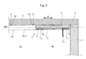
- FIG. 3 shows a detail of a schematic sectional view of an embodiment of the present invention in the region of the frontal mounting in the covered niche area 8b, wherein the covered niche area 8b concealing Nischenabdeckwand 8 'is removed.
- the running rail 3 is taken up by a base profile 10, but it is not shown in the longitudinal sectional view, since the cutting plane in the region of the externally attached to a leg portion 10.1 of the base section 10 guiding and holding means 9 extends.
- shims 14 are inserted, so that the suspension device 1 has a slight downward slope towards the open passage area 8a.
- the access to the frontal attachment means 5 ' is thereby additionally improved.
- the fastening means 5 for fastening the suspension device 1 to the ceiling 6 penetrate the Unterlegklötze 14, but they can also be arranged next to the Unterlegklötzen 14.
- the fixedly connected to the stop element 12 fixing element 13 is in the form of a rotatably mounted threaded rod.
- the threaded rod 13 and thus the attached stop element 12 by means of lock 15 in the direction of the main axis HA of the suspension device 1 and in the direction R of the sliding door 2 are moved.
Landscapes
- Engineering & Computer Science (AREA)
- Mechanical Engineering (AREA)
- Support Devices For Sliding Doors (AREA)
Applications Claiming Priority (1)
| Application Number | Priority Date | Filing Date | Title |
|---|---|---|---|
| DE102011100698A DE102011100698B4 (de) | 2011-05-06 | 2011-05-06 | Aufhängevorrichtung für Schiebetüren sowie zugehöriges Verfahren zur stirnseitigen Befestigung einer derartigen Aufhängevorrichtung |
Publications (2)
| Publication Number | Publication Date |
|---|---|
| EP2520748A2 true EP2520748A2 (fr) | 2012-11-07 |
| EP2520748A3 EP2520748A3 (fr) | 2013-12-11 |
Family
ID=45992099
Family Applications (1)
| Application Number | Title | Priority Date | Filing Date |
|---|---|---|---|
| EP12164642.6A Withdrawn EP2520748A3 (fr) | 2011-05-06 | 2012-04-18 | Dispositif de suspension pour portes coulissantes ainsi que le procédé correspondant de fixation frontale du dispositif de suspension de ce type |
Country Status (2)
| Country | Link |
|---|---|
| EP (1) | EP2520748A3 (fr) |
| DE (1) | DE102011100698B4 (fr) |
Families Citing this family (1)
| Publication number | Priority date | Publication date | Assignee | Title |
|---|---|---|---|---|
| DE202019107092U1 (de) * | 2019-12-18 | 2021-03-19 | Cool It Isoliersysteme Gmbh | Schiebetür für Gefrier-, Kühl- oder Betriebsräume |
Citations (4)
| Publication number | Priority date | Publication date | Assignee | Title |
|---|---|---|---|---|
| DE202007002905U1 (de) | 2007-02-26 | 2007-05-10 | Gilch, Ludwig | Schienensystem für eine Schiebetür |
| EP1630334B1 (fr) | 2004-08-17 | 2008-04-09 | Woelm Gesellschaft mit beschränkter Haftung | Dispositif de suspension pour portes coulissantes |
| DE102006057816A1 (de) | 2006-12-06 | 2008-06-12 | Bernhard Feigl | Halterung zur Befestigung einer Laufschiene |
| EP2476843A2 (fr) * | 2011-01-14 | 2012-07-18 | Eku Ag | Elément de fixation pour la fixation frontale d'un rail de guidage |
Family Cites Families (1)
| Publication number | Priority date | Publication date | Assignee | Title |
|---|---|---|---|---|
| DE29908332U1 (de) * | 1999-05-07 | 1999-10-28 | Hermann Francksen Nachf. GmbH & Co. KG, 28719 Bremen | Aufhängevorrichtung für eine Schiebetür |
-
2011
- 2011-05-06 DE DE102011100698A patent/DE102011100698B4/de not_active Expired - Fee Related
-
2012
- 2012-04-18 EP EP12164642.6A patent/EP2520748A3/fr not_active Withdrawn
Patent Citations (4)
| Publication number | Priority date | Publication date | Assignee | Title |
|---|---|---|---|---|
| EP1630334B1 (fr) | 2004-08-17 | 2008-04-09 | Woelm Gesellschaft mit beschränkter Haftung | Dispositif de suspension pour portes coulissantes |
| DE102006057816A1 (de) | 2006-12-06 | 2008-06-12 | Bernhard Feigl | Halterung zur Befestigung einer Laufschiene |
| DE202007002905U1 (de) | 2007-02-26 | 2007-05-10 | Gilch, Ludwig | Schienensystem für eine Schiebetür |
| EP2476843A2 (fr) * | 2011-01-14 | 2012-07-18 | Eku Ag | Elément de fixation pour la fixation frontale d'un rail de guidage |
Also Published As
| Publication number | Publication date |
|---|---|
| DE102011100698B4 (de) | 2012-12-06 |
| DE102011100698A1 (de) | 2012-11-08 |
| EP2520748A3 (fr) | 2013-12-11 |
Similar Documents
| Publication | Publication Date | Title |
|---|---|---|
| EP0705954A1 (fr) | Aile coulissante pour la fermeture suivant les besoins d'une façade ouverte d'un balcon, jardin d'hiver et similaires | |
| DE102011011113B4 (de) | Rahmensystem eines Partikelschutzgitters | |
| DE102014119145A1 (de) | Schiebetor und Baukastensystem für ein Schiebetor | |
| DE102011100698B4 (de) | Aufhängevorrichtung für Schiebetüren sowie zugehöriges Verfahren zur stirnseitigen Befestigung einer derartigen Aufhängevorrichtung | |
| EP2700778A1 (fr) | Dispositif de soutien déplaçable d'une plaque | |
| EP1485563B1 (fr) | Dispositif de support et de guidage permettant de fixer des elements porte ou mur mobiles suspendus | |
| DE102015107324B4 (de) | Profilschienensystem für den Einbau von Schiebetüren in Hohlwände | |
| EP3088647B1 (fr) | Système à rails pour un dispositif de guidage | |
| EP3480407B1 (fr) | Élément coulissant vertical | |
| DE29511379U1 (de) | Auflaufbock | |
| CH702394B1 (de) | Schiebewand mit wenigstens zwei Flügeln. | |
| DE29813478U1 (de) | Schiebetürenanordnung für Möbel | |
| DE29516438U1 (de) | Schiebetürbeschlag | |
| EP3029227B1 (fr) | Ferrure dotée d'une plage de serrage réglable | |
| EP2527575B1 (fr) | Ferrure de porte coulissante | |
| DE202007002905U1 (de) | Schienensystem für eine Schiebetür | |
| EP2085533B1 (fr) | Dispositif de liaison destiné à la liaison du degré et du limon d'un escalier ou d'éléments de meubles | |
| DE10035956C2 (de) | Laufschienen-Klemmhalter für die Befestigung von Laufschienen für Schiebetürsysteme | |
| DE102009011025B4 (de) | Insektenschutzeinrichtung | |
| DE102020132044A1 (de) | Schiebetürbeschlag und Verfahren zur Montage eines Schiebetürbeschlages | |
| EP3816383A1 (fr) | Agencement de porte coulissante | |
| DE102013011879A1 (de) | Druckstange mit Verspannungseinrichtung | |
| EP3146877B1 (fr) | Cabine de douche | |
| DE3224395A1 (de) | Teleskopierbarer beschlag fuer schiebetueren | |
| DE102012004940B4 (de) | Laufschiene für eine Schiebetür |
Legal Events
| Date | Code | Title | Description |
|---|---|---|---|
| PUAI | Public reference made under article 153(3) epc to a published international application that has entered the european phase |
Free format text: ORIGINAL CODE: 0009012 |
|
| AK | Designated contracting states |
Kind code of ref document: A2 Designated state(s): AL AT BE BG CH CY CZ DE DK EE ES FI FR GB GR HR HU IE IS IT LI LT LU LV MC MK MT NL NO PL PT RO RS SE SI SK SM TR |
|
| AX | Request for extension of the european patent |
Extension state: BA ME |
|
| PUAL | Search report despatched |
Free format text: ORIGINAL CODE: 0009013 |
|
| AK | Designated contracting states |
Kind code of ref document: A3 Designated state(s): AL AT BE BG CH CY CZ DE DK EE ES FI FR GB GR HR HU IE IS IT LI LT LU LV MC MK MT NL NO PL PT RO RS SE SI SK SM TR |
|
| AX | Request for extension of the european patent |
Extension state: BA ME |
|
| RIC1 | Information provided on ipc code assigned before grant |
Ipc: E05D 15/06 20060101AFI20131106BHEP |
|
| 17P | Request for examination filed |
Effective date: 20140325 |
|
| RBV | Designated contracting states (corrected) |
Designated state(s): AL AT BE BG CH CY CZ DE DK EE ES FI FR GB GR HR HU IE IS IT LI LT LU LV MC MK MT NL NO PL PT RO RS SE SI SK SM TR |
|
| 17Q | First examination report despatched |
Effective date: 20160223 |
|
| STAA | Information on the status of an ep patent application or granted ep patent |
Free format text: STATUS: THE APPLICATION IS DEEMED TO BE WITHDRAWN |
|
| 18D | Application deemed to be withdrawn |
Effective date: 20160705 |