EP2522459B1 - Meule super abrasive, procédé de fabrication de plaquette utilisant la meule et plaquette - Google Patents
Meule super abrasive, procédé de fabrication de plaquette utilisant la meule et plaquette Download PDFInfo
- Publication number
- EP2522459B1 EP2522459B1 EP10843072.9A EP10843072A EP2522459B1 EP 2522459 B1 EP2522459 B1 EP 2522459B1 EP 10843072 A EP10843072 A EP 10843072A EP 2522459 B1 EP2522459 B1 EP 2522459B1
- Authority
- EP
- European Patent Office
- Prior art keywords
- super abrasive
- abrasive wheel
- wheel according
- grinding fluid
- view
- Prior art date
- Legal status (The legal status is an assumption and is not a legal conclusion. Google has not performed a legal analysis and makes no representation as to the accuracy of the status listed.)
- Not-in-force
Links
Images











Classifications
-
- B—PERFORMING OPERATIONS; TRANSPORTING
- B24—GRINDING; POLISHING
- B24D—TOOLS FOR GRINDING, BUFFING OR SHARPENING
- B24D7/00—Bonded abrasive wheels, or wheels with inserted abrasive blocks, designed for acting otherwise than only by their periphery, e.g. by the front face; Bushings or mountings therefor
- B24D7/06—Bonded abrasive wheels, or wheels with inserted abrasive blocks, designed for acting otherwise than only by their periphery, e.g. by the front face; Bushings or mountings therefor with inserted abrasive blocks, e.g. segmental
-
- B—PERFORMING OPERATIONS; TRANSPORTING
- B24—GRINDING; POLISHING
- B24B—MACHINES, DEVICES, OR PROCESSES FOR GRINDING OR POLISHING; DRESSING OR CONDITIONING OF ABRADING SURFACES; FEEDING OF GRINDING, POLISHING, OR LAPPING AGENTS
- B24B55/00—Safety devices for grinding or polishing machines; Accessories fitted to grinding or polishing machines for keeping tools or parts of the machine in good working condition
- B24B55/02—Equipment for cooling the grinding surfaces, e.g. devices for feeding coolant
-
- B—PERFORMING OPERATIONS; TRANSPORTING
- B24—GRINDING; POLISHING
- B24B—MACHINES, DEVICES, OR PROCESSES FOR GRINDING OR POLISHING; DRESSING OR CONDITIONING OF ABRADING SURFACES; FEEDING OF GRINDING, POLISHING, OR LAPPING AGENTS
- B24B7/00—Machines or devices designed for grinding plane surfaces on work, including polishing plane glass surfaces; Accessories therefor
- B24B7/20—Machines or devices designed for grinding plane surfaces on work, including polishing plane glass surfaces; Accessories therefor characterised by a special design with respect to properties of the material of non-metallic articles to be ground
- B24B7/22—Machines or devices designed for grinding plane surfaces on work, including polishing plane glass surfaces; Accessories therefor characterised by a special design with respect to properties of the material of non-metallic articles to be ground for grinding inorganic material, e.g. stone, ceramics, porcelain
- B24B7/228—Machines or devices designed for grinding plane surfaces on work, including polishing plane glass surfaces; Accessories therefor characterised by a special design with respect to properties of the material of non-metallic articles to be ground for grinding inorganic material, e.g. stone, ceramics, porcelain for grinding thin, brittle parts, e.g. semiconductors, wafers
-
- B—PERFORMING OPERATIONS; TRANSPORTING
- B24—GRINDING; POLISHING
- B24D—TOOLS FOR GRINDING, BUFFING OR SHARPENING
- B24D7/00—Bonded abrasive wheels, or wheels with inserted abrasive blocks, designed for acting otherwise than only by their periphery, e.g. by the front face; Bushings or mountings therefor
- B24D7/10—Bonded abrasive wheels, or wheels with inserted abrasive blocks, designed for acting otherwise than only by their periphery, e.g. by the front face; Bushings or mountings therefor with cooling provisions
-
- Y—GENERAL TAGGING OF NEW TECHNOLOGICAL DEVELOPMENTS; GENERAL TAGGING OF CROSS-SECTIONAL TECHNOLOGIES SPANNING OVER SEVERAL SECTIONS OF THE IPC; TECHNICAL SUBJECTS COVERED BY FORMER USPC CROSS-REFERENCE ART COLLECTIONS [XRACs] AND DIGESTS
- Y10—TECHNICAL SUBJECTS COVERED BY FORMER USPC
- Y10T—TECHNICAL SUBJECTS COVERED BY FORMER US CLASSIFICATION
- Y10T428/00—Stock material or miscellaneous articles
- Y10T428/24—Structurally defined web or sheet [e.g., overall dimension, etc.]
- Y10T428/24355—Continuous and nonuniform or irregular surface on layer or component [e.g., roofing, etc.]
Definitions
- JP 2005 138235 A discloses a generic super abrasive wheel according to the preamble of claim 1.
- a plurality of the protrusion portions are provided on an inner circumferential side of the super abrasive layer, and in the protrusion portions adjacent to each other, the height from the reference surface is lower in the protrusion portion on the inner circumferential side than in the protrusion portion on the outer circumferential side.
- the grinding fluid supplied from the inner circumferential side collides against the annular protrusion portion of the protrusion member and diffuses toward the super abrasive layer.
- the grinding fluid can be supplied uniformly between the super abrasive layer and a workpiece.
- the grinding fluid can be prevented from being stored in the fluid reservoir, thereby realizing stable rotation.
- the protrusion member is separate from the core. Therefore, the protrusion member can be provided on a conventional core without a protrusion portion. Thus, storage of fluid can be prevented, thereby realizing stable rotation.
- the present invention provides a super abrasive wheel capable of uniformly supplying grinding fluid between a super abrasive layer and a workpiece.
- the grinding fluid is prevented from being stored in a reservoir, and stable rotation is thus realized.
- the present invention also achieves the effect of stably keeping a sharp edge for a long time, thereby achieving a good working surface quality with less burning of a workpiece.
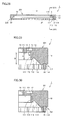
- Fig. 1 is a front view of a super abrasive wheel according to a first embodiment of the present invention.
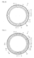
- Fig. 2 is a plan view of the super abrasive wheel according to the first embodiment of the invention.
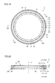
- Fig. 3 is a bottom view of the super abrasive wheel according to the first embodiment of the invention.
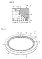
- Fig. 4 is a cross-sectional view taken along a line IV-IV in Fig. 3 .
- Fig. 5 is a cross-sectional view taken along a line V-V in Fig. 3 .
- Fig. 6 is an enlarged cross-sectional view showing a portion surrounded by a line VI-VI in Fig. 4 .
- FIG. 7 is an enlarged cross-sectional view showing a portion surrounded by a line VII-VII in Fig. 5 .
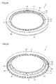
- Fig. 8 is a perspective view according to an aspect of the super abrasive wheel according to the first embodiment of the invention.
- Fig. 9 is a perspective view according to another aspect of the super abrasive wheel according to the first embodiment of the invention.
- first rising wall 111, first inverted taper surface 112, and outer taper surface 113 are each configured so as to extend in the circumferential direction of the circular core 10.
- first rising wall 111 which is a wall surface on the inner circumferential side of first protrusion portion 121 is parallel to rotation axis 3.
- Height A from reference surface 110 of first protrusion portion 121 located on the innermost circumferential side is 3 mm or more. The difference between height B and height A is 1 mm or more.
- First protrusion portion 121 is shaped like a circular ring. First protrusion portion 121 has a function of making the grinding fluid into finer particles and diffusing the grinding fluid uniformly.
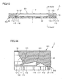
- Fig. 42 is a bottom view of the super abrasive wheel according to an eighth embodiment of the invention.
- Fig. 43 is a cross-sectional view taken along a line XLIII-XLIII in Fig. 42 .
- Fig. 44 is an enlarged cross-sectional view showing a portion surrounded by a line XLIV-XLIV in Fig. 43 .
- Fig. 45 is a perspective view according to an aspect of the super abrasive wheel according to the eighth embodiment of the invention.
- Fig. 46 is a perspective view according to another aspect of the super abrasive wheel according to the eighth embodiment of the invention.
- Fig. 47 is a diagram for explaining a grinding process in the super abrasive wheel according to a ninth embodiment of the invention.
- a baffle 701 may be used to diffuse grinding fluid. Specifically, grinding fluid is supplied from a nozzle 702 along the axial direction. The grinding fluid flows radially along baffle 701 and is discharged radially outward as shown by arrow F to collide against first rising wall 111. Then, after passing through end portion 115, the grinding fluid diffuses in the direction shown by arrow F 1 and collides against outer taper surface 113. The grinding fluid is thereafter supplied to the interface between super abrasive layer 20 and wafer 601.
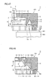
- Fig. 53 is a cross-sectional view of the super abrasive wheel according to a fifteenth embodiment of the invention.
- the boundary between protrusion member 1000 and core 10 is an inclined surface. Part of the boundary between protrusion member 1000 and core 10 is on reference surface 110.
- Fig. 54 is a cross-sectional view of the super abrasive wheel according to a sixteenth embodiment of the invention. Referring to Fig. 54 , in super abrasive wheel 1 according to the sixteenth embodiment, the boundary surface between protrusion member 1000 and core 10 is stepwise.
- Fig. 56 is a bottom view of the super abrasive wheel according to an eighteenth embodiment of the invention.
- Fig. 57 is a cross-sectional view taken along an arrow LVII-LVII in Fig. 56 .
- protrusion member 1000 is attached on reference surface 110 of core 10.
- Protrusion member 1000 is formed like a cover and has grinding fluid supply holes 13 in a center region thereof. Grinding fluid is supplied from grinding fluid supply holes 13. The supplied grinding fluid is scattered in the outer circumferential direction by centrifugal force and reaches first rising wall 111.
- Fig. 64 is a bottom view of the super abrasive wheel according to a twenty-second embodiment of the invention.
- Fig. 65 is a cross-sectional view taken along a line LXV-LXV in Fig. 64 .
- protrusion member 1000 has first protrusion portion 121, first inverted taper surface 112, second protrusion portion 122, second inverted taper surface 117, a third protrusion portion 123, and a third inverted taper surface 119.
- a ⁇ C ⁇ D ⁇ B holds.
- Fig. 66 is a bottom view of the super abrasive wheel according to a twenty-third embodiment of the invention.
- Fig. 67 is a cross-sectional view taken along a line LXVII-LXVII in Fig. 66 .
- grinding fluid supply hole 13 penetrates through protrusion member 1000 so as to extend toward the outer circumference.
- Fig. 76 is a cross-sectional view of a super abrasive wheel according to a comparative product.
- Fig. 77 is a bottom view of a super abrasive wheel according to a product of the present invention.
- a comparative product having no protrusion portion
- a product of the present invention having the shape shown in Fig. 77 were prepared. The sizes of these samples are shown below.
- the current value (A) required to rotate the super abrasive wheel was 3.5
- the amount ( ⁇ ) of wear of super abrasive layer 20 was 0.86
- the surface roughness Ra (nm) of the work was 2.0.
- the current value (A) was 3.5
- the amount of wear ( ⁇ m) was 0.42
- the surface roughness Ra (nm) was 1.2.
Landscapes
- Engineering & Computer Science (AREA)
- Mechanical Engineering (AREA)
- Chemical & Material Sciences (AREA)
- Ceramic Engineering (AREA)
- Inorganic Chemistry (AREA)
- Polishing Bodies And Polishing Tools (AREA)
- Mechanical Treatment Of Semiconductor (AREA)
Claims (9)
- Meule super abrasive (1) comprenant :un moyeu (10) configuré de manière à tourner autour d'un axe de rotation ; etune couche super abrasive (20) liée au moyeu,le moyeu présentant une première surface (201) et une seconde surface (202) située à l'opposée de la première surface, dans laquelleune partie en saillie annulaire (121) s'étendant dans une direction s'écartant de la première surface est agencée au niveau d'une partie de la seconde surface qui est entourée par la couche super abrasive,une surface de référence (110) est formée au niveau d'une partie de la seconde surface sur la face interne de la partie en saillie, etune hauteur à partir de la surface de référence vers la partie en saillie est désignée par A,caractérisée par :le fait qu'une partie supérieure (114) présentant une hauteur B à partir de la surface de référence est formée au niveau d'une partie de la seconde surface entre la partie en saillie et la couche super abrasive, dans laquelle la hauteur B est supérieure à la hauteur A.
- Meule super abrasive selon la revendication 1, dans laquelle une surface de paroi sur une face circonférentielle interne de la partie en saillie est approximativement parallèle à l'axe de rotation.
- Meule super abrasive selon la revendication 1, dans laquelle une pluralité des parties en saillie est agencée sur une face circonférentielle interne de la couche super abrasive et, sur les parties en saillie adjacentes les unes aux autres, la hauteur à partir de la surface de référence est inférieure dans la partie en saillie sur la face circonférentielle interne à celle dans la partie en saillie sur la face circonférentielle externe.
- Meule super abrasive selon la revendication 1, dans laquelle la hauteur à partir de la surface de référence de la partie en saillie située sur une face circonférentielle la plus à l'intérieur est supérieure ou égale à 3 mm.
- Meule super abrasive selon la revendication 1, dans laquelle une différence entre la hauteur B et la hauteur A est supérieure ou égale à 1 mm.
- Meule super abrasive selon la revendication 1, dans laquelle la partie en saillie est en forme de bague circulaire.
- Meule super abrasive selon la revendication 1, dans laquelle la partie en saillie présente la fonction d'affiner les particules de fluide de meulage et de répartir de manière uniforme le fluide de meulage.
- Meule super abrasive (1) selon l'une quelconque des revendications 1 à 7, dans laquelle :un élément en saillie (1000) est agencé au niveau de ladite partie de la seconde surface qui est entourée par la couche super abrasive, ledit élément en saillie comporte ladite partie en saillie annulaire (121).
- Procédé de fabrication d'une pastille, comprenant la mise en contact de la couche super abrasive de la meule super abrasive selon la revendication 1 avec une pastille, et le polissage de la pastille tout en délivrant un fluide de meulage à partir d'une face circonférentielle interne de la partie de saillie.
Applications Claiming Priority (2)
| Application Number | Priority Date | Filing Date | Title |
|---|---|---|---|
| JP2010004998 | 2010-01-13 | ||
| PCT/JP2010/059748 WO2011086715A1 (fr) | 2010-01-13 | 2010-06-09 | Meule super abrasive, procédé de fabrication de plaquette utilisant la meule et plaquette |
Publications (3)
| Publication Number | Publication Date |
|---|---|
| EP2522459A1 EP2522459A1 (fr) | 2012-11-14 |
| EP2522459A4 EP2522459A4 (fr) | 2013-10-16 |
| EP2522459B1 true EP2522459B1 (fr) | 2014-11-12 |
Family
ID=44304015
Family Applications (1)
| Application Number | Title | Priority Date | Filing Date |
|---|---|---|---|
| EP10843072.9A Not-in-force EP2522459B1 (fr) | 2010-01-13 | 2010-06-09 | Meule super abrasive, procédé de fabrication de plaquette utilisant la meule et plaquette |
Country Status (7)
| Country | Link |
|---|---|
| US (1) | US9011206B2 (fr) |
| EP (1) | EP2522459B1 (fr) |
| JP (1) | JP5465257B2 (fr) |
| KR (1) | KR101395947B1 (fr) |
| CN (1) | CN102712076B (fr) |
| TW (1) | TWI462802B (fr) |
| WO (1) | WO2011086715A1 (fr) |
Families Citing this family (11)
| Publication number | Priority date | Publication date | Assignee | Title |
|---|---|---|---|---|
| CN103249528B (zh) * | 2010-12-06 | 2014-11-12 | 小松Ntc株式会社 | 磨削砂轮 |
| JP6117030B2 (ja) * | 2013-07-08 | 2017-04-19 | Sumco Techxiv株式会社 | 飛散板、研削ホイール、および、研削装置 |
| JP2015139859A (ja) * | 2014-01-30 | 2015-08-03 | 株式会社ニートレックス本社 | 研削液供給具および研削ホイール |
| JP2016168660A (ja) * | 2015-03-13 | 2016-09-23 | 株式会社ディスコ | 研削ホイール |
| JP6865567B2 (ja) * | 2016-12-01 | 2021-04-28 | 旭ダイヤモンド工業株式会社 | 研削ホイール |
| JP7067878B2 (ja) * | 2017-07-04 | 2022-05-16 | 株式会社ディスコ | 研削装置 |
| CN212095976U (zh) * | 2020-03-30 | 2020-12-08 | 桂林创源金刚石有限公司 | 一种高转速杯形砂轮 |
| CN110919554B (zh) * | 2019-12-19 | 2024-04-16 | 宋京新 | 组合式多功能电镀砂轮 |
| JP2022096834A (ja) * | 2020-12-18 | 2022-06-30 | 株式会社ディスコ | 研削ホイール |
| TWI809902B (zh) * | 2022-05-30 | 2023-07-21 | 全鑫精密工業股份有限公司 | 研磨盤高壓排屑清潔冷卻裝置 |
| WO2026015651A1 (fr) * | 2024-07-11 | 2026-01-15 | Globalwafers Co., Ltd. | Appareil de broyage double face et procédés ayant une base de roue avec éléments abrasifs poreux |
Family Cites Families (17)
| Publication number | Priority date | Publication date | Assignee | Title |
|---|---|---|---|---|
| US2307312A (en) * | 1941-09-04 | 1943-01-05 | Draper Corp | Abrading wheel |
| FR2537034B1 (fr) * | 1982-12-01 | 1987-01-16 | Smit Fils J K | Meule |
| JPS60259378A (ja) * | 1984-06-01 | 1985-12-21 | Hitachi Seiko Ltd | 研削機における研削液供給方法およびその装置 |
| JPS6154459U (fr) * | 1984-09-14 | 1986-04-12 | ||
| US5259148A (en) * | 1991-11-12 | 1993-11-09 | Wiand Ronald C | Ring generator wheel with improved coolant flow |
| JPH0731268U (ja) | 1993-11-08 | 1995-06-13 | 株式会社ディスコ | 研削砥石 |
| RU2179106C2 (ru) | 1995-02-03 | 2002-02-10 | Си-Эм-И Бластинг энд Майнинг Эквипмент Лтд. | Шлифовальная насадка и держатель |
| SG70097A1 (en) * | 1997-08-15 | 2000-01-25 | Disio Corp | Apparatus and method for machining workpieces by flushing working liquid to the tool-and-workpiece interface |
| CN1130275C (zh) * | 1998-04-21 | 2003-12-10 | 蒂罗利特磨料机械斯沃罗夫斯基两合公司 | 磨轮和具有它的磨削设备 |
| JP2001205560A (ja) * | 2000-01-28 | 2001-07-31 | Disco Abrasive Syst Ltd | 研削ホイール及び該研削ホイールの製造方法 |
| JP3791610B2 (ja) * | 2000-09-13 | 2006-06-28 | 株式会社アライドマテリアル | 鏡面加工用超砥粒ホイール |
| JP4885376B2 (ja) | 2001-07-04 | 2012-02-29 | 株式会社ディスコ | 研削ホイール |
| SG119140A1 (en) * | 2001-07-04 | 2006-02-28 | Disco Corp | Grinding wheel |
| US6685755B2 (en) * | 2001-11-21 | 2004-02-03 | Saint-Gobain Abrasives Technology Company | Porous abrasive tool and method for making the same |
| AT502503B1 (de) * | 2003-09-04 | 2007-04-15 | Schrottner Gerhard | Ringsystem zur mediumsführung bei schleifscheiben |
| JP2005138235A (ja) * | 2003-11-07 | 2005-06-02 | Disco Abrasive Syst Ltd | 研削ホイールの着脱機構,研削装置,研削ホイールの着脱冶具,及び研削ホイールの装着方法 |
| JP2008238389A (ja) * | 2007-03-29 | 2008-10-09 | Mezoteku Dia Kk | Cmpパッドコンディショナ |
-
2010
- 2010-06-09 WO PCT/JP2010/059748 patent/WO2011086715A1/fr not_active Ceased
- 2010-06-09 US US13/519,210 patent/US9011206B2/en active Active
- 2010-06-09 CN CN201080061275.6A patent/CN102712076B/zh active Active
- 2010-06-09 KR KR1020127021055A patent/KR101395947B1/ko active Active
- 2010-06-09 EP EP10843072.9A patent/EP2522459B1/fr not_active Not-in-force
- 2010-06-09 JP JP2011549843A patent/JP5465257B2/ja active Active
- 2010-06-11 TW TW099119024A patent/TWI462802B/zh active
Also Published As
| Publication number | Publication date |
|---|---|
| JP5465257B2 (ja) | 2014-04-09 |
| EP2522459A1 (fr) | 2012-11-14 |
| JPWO2011086715A1 (ja) | 2013-05-16 |
| CN102712076B (zh) | 2014-10-15 |
| TW201124232A (en) | 2011-07-16 |
| US20120288677A1 (en) | 2012-11-15 |
| KR20120112785A (ko) | 2012-10-11 |
| WO2011086715A1 (fr) | 2011-07-21 |
| US9011206B2 (en) | 2015-04-21 |
| EP2522459A4 (fr) | 2013-10-16 |
| KR101395947B1 (ko) | 2014-05-16 |
| CN102712076A (zh) | 2012-10-03 |
| TWI462802B (zh) | 2014-12-01 |
Similar Documents
| Publication | Publication Date | Title |
|---|---|---|
| EP2522459B1 (fr) | Meule super abrasive, procédé de fabrication de plaquette utilisant la meule et plaquette | |
| US5846125A (en) | Truing wheel with incorporated cooling | |
| JP3444819B2 (ja) | 回転円盤砥石 | |
| US20190134782A1 (en) | Grinding wheel | |
| CN102166731B (zh) | 磨削装置 | |
| US9975217B2 (en) | Scattering plate, grinding wheel, and grinding device | |
| CN101522372B (zh) | 在磨削操作中冷却剂动态压力释放方法、利用该释放方法的磨削方法以及在该磨削方法中使用的砂轮 | |
| CN102917826B (zh) | 用于用在中空主轴机床上的直通冷却剂适配器 | |
| CN104858737A (zh) | 工件的平面磨削方法 | |
| JP2003300165A (ja) | セグメントタイプ砥石 | |
| JP2015139859A (ja) | 研削液供給具および研削ホイール | |
| JP3978118B2 (ja) | カップホイ−ル型砥石を備えた研削ヘッド構造 | |
| JP2018199197A (ja) | 超砥粒ホイール | |
| JP2704533B2 (ja) | パイプ砥石 | |
| KR100338404B1 (ko) | 컵휠형지석 및 그것을 구비한 평면연삭장치 | |
| JP4837853B2 (ja) | 研削ホイール | |
| JP6197580B2 (ja) | キャリアプレート及びワークの両面研磨装置 | |
| JPH11207636A (ja) | カップ型砥石 | |
| JP2013086243A (ja) | カップ形砥石を用いた研削盤における給液構造 | |
| JPH0731268U (ja) | 研削砥石 | |
| JP4885376B2 (ja) | 研削ホイール | |
| JPH11235670A (ja) | 回転砥石の研削液供給方法および同回転砥石 | |
| JPH052286Y2 (fr) | ||
| JPH078131Y2 (ja) | ダイヤモンド工具 | |
| JP2009255185A (ja) | 砥石 |
Legal Events
| Date | Code | Title | Description |
|---|---|---|---|
| PUAI | Public reference made under article 153(3) epc to a published international application that has entered the european phase |
Free format text: ORIGINAL CODE: 0009012 |
|
| 17P | Request for examination filed |
Effective date: 20120807 |
|
| AK | Designated contracting states |
Kind code of ref document: A1 Designated state(s): AL AT BE BG CH CY CZ DE DK EE ES FI FR GB GR HR HU IE IS IT LI LT LU LV MC MK MT NL NO PL PT RO SE SI SK SM TR |
|
| DAX | Request for extension of the european patent (deleted) | ||
| A4 | Supplementary search report drawn up and despatched |
Effective date: 20130918 |
|
| RIC1 | Information provided on ipc code assigned before grant |
Ipc: B24D 7/10 20060101ALI20130912BHEP Ipc: B24B 55/02 20060101AFI20130912BHEP |
|
| 17Q | First examination report despatched |
Effective date: 20140221 |
|
| GRAP | Despatch of communication of intention to grant a patent |
Free format text: ORIGINAL CODE: EPIDOSNIGR1 |
|
| INTG | Intention to grant announced |
Effective date: 20140616 |
|
| GRAS | Grant fee paid |
Free format text: ORIGINAL CODE: EPIDOSNIGR3 |
|
| GRAA | (expected) grant |
Free format text: ORIGINAL CODE: 0009210 |
|
| AK | Designated contracting states |
Kind code of ref document: B1 Designated state(s): AL AT BE BG CH CY CZ DE DK EE ES FI FR GB GR HR HU IE IS IT LI LT LU LV MC MK MT NL NO PL PT RO SE SI SK SM TR |
|
| REG | Reference to a national code |
Ref country code: GB Ref legal event code: FG4D |
|
| REG | Reference to a national code |
Ref country code: CH Ref legal event code: EP |
|
| REG | Reference to a national code |
Ref country code: AT Ref legal event code: REF Ref document number: 695441 Country of ref document: AT Kind code of ref document: T Effective date: 20141115 |
|
| REG | Reference to a national code |
Ref country code: IE Ref legal event code: FG4D |
|
| REG | Reference to a national code |
Ref country code: DE Ref legal event code: R096 Ref document number: 602010020289 Country of ref document: DE Effective date: 20141231 |
|
| REG | Reference to a national code |
Ref country code: NL Ref legal event code: VDEP Effective date: 20141112 |
|
| REG | Reference to a national code |
Ref country code: AT Ref legal event code: MK05 Ref document number: 695441 Country of ref document: AT Kind code of ref document: T Effective date: 20141112 |
|
| PG25 | Lapsed in a contracting state [announced via postgrant information from national office to epo] |
Ref country code: PT Free format text: LAPSE BECAUSE OF FAILURE TO SUBMIT A TRANSLATION OF THE DESCRIPTION OR TO PAY THE FEE WITHIN THE PRESCRIBED TIME-LIMIT Effective date: 20150312 Ref country code: IS Free format text: LAPSE BECAUSE OF FAILURE TO SUBMIT A TRANSLATION OF THE DESCRIPTION OR TO PAY THE FEE WITHIN THE PRESCRIBED TIME-LIMIT Effective date: 20150312 Ref country code: NL Free format text: LAPSE BECAUSE OF FAILURE TO SUBMIT A TRANSLATION OF THE DESCRIPTION OR TO PAY THE FEE WITHIN THE PRESCRIBED TIME-LIMIT Effective date: 20141112 Ref country code: ES Free format text: LAPSE BECAUSE OF FAILURE TO SUBMIT A TRANSLATION OF THE DESCRIPTION OR TO PAY THE FEE WITHIN THE PRESCRIBED TIME-LIMIT Effective date: 20141112 Ref country code: NO Free format text: LAPSE BECAUSE OF FAILURE TO SUBMIT A TRANSLATION OF THE DESCRIPTION OR TO PAY THE FEE WITHIN THE PRESCRIBED TIME-LIMIT Effective date: 20150212 Ref country code: FI Free format text: LAPSE BECAUSE OF FAILURE TO SUBMIT A TRANSLATION OF THE DESCRIPTION OR TO PAY THE FEE WITHIN THE PRESCRIBED TIME-LIMIT Effective date: 20141112 Ref country code: LT Free format text: LAPSE BECAUSE OF FAILURE TO SUBMIT A TRANSLATION OF THE DESCRIPTION OR TO PAY THE FEE WITHIN THE PRESCRIBED TIME-LIMIT Effective date: 20141112 |
|
| PG25 | Lapsed in a contracting state [announced via postgrant information from national office to epo] |
Ref country code: LV Free format text: LAPSE BECAUSE OF FAILURE TO SUBMIT A TRANSLATION OF THE DESCRIPTION OR TO PAY THE FEE WITHIN THE PRESCRIBED TIME-LIMIT Effective date: 20141112 Ref country code: AT Free format text: LAPSE BECAUSE OF FAILURE TO SUBMIT A TRANSLATION OF THE DESCRIPTION OR TO PAY THE FEE WITHIN THE PRESCRIBED TIME-LIMIT Effective date: 20141112 Ref country code: HR Free format text: LAPSE BECAUSE OF FAILURE TO SUBMIT A TRANSLATION OF THE DESCRIPTION OR TO PAY THE FEE WITHIN THE PRESCRIBED TIME-LIMIT Effective date: 20141112 Ref country code: CY Free format text: LAPSE BECAUSE OF FAILURE TO SUBMIT A TRANSLATION OF THE DESCRIPTION OR TO PAY THE FEE WITHIN THE PRESCRIBED TIME-LIMIT Effective date: 20141112 Ref country code: PL Free format text: LAPSE BECAUSE OF FAILURE TO SUBMIT A TRANSLATION OF THE DESCRIPTION OR TO PAY THE FEE WITHIN THE PRESCRIBED TIME-LIMIT Effective date: 20141112 Ref country code: GR Free format text: LAPSE BECAUSE OF FAILURE TO SUBMIT A TRANSLATION OF THE DESCRIPTION OR TO PAY THE FEE WITHIN THE PRESCRIBED TIME-LIMIT Effective date: 20150213 Ref country code: SE Free format text: LAPSE BECAUSE OF FAILURE TO SUBMIT A TRANSLATION OF THE DESCRIPTION OR TO PAY THE FEE WITHIN THE PRESCRIBED TIME-LIMIT Effective date: 20141112 |
|
| PG25 | Lapsed in a contracting state [announced via postgrant information from national office to epo] |
Ref country code: SK Free format text: LAPSE BECAUSE OF FAILURE TO SUBMIT A TRANSLATION OF THE DESCRIPTION OR TO PAY THE FEE WITHIN THE PRESCRIBED TIME-LIMIT Effective date: 20141112 Ref country code: CZ Free format text: LAPSE BECAUSE OF FAILURE TO SUBMIT A TRANSLATION OF THE DESCRIPTION OR TO PAY THE FEE WITHIN THE PRESCRIBED TIME-LIMIT Effective date: 20141112 Ref country code: RO Free format text: LAPSE BECAUSE OF FAILURE TO SUBMIT A TRANSLATION OF THE DESCRIPTION OR TO PAY THE FEE WITHIN THE PRESCRIBED TIME-LIMIT Effective date: 20141112 Ref country code: DK Free format text: LAPSE BECAUSE OF FAILURE TO SUBMIT A TRANSLATION OF THE DESCRIPTION OR TO PAY THE FEE WITHIN THE PRESCRIBED TIME-LIMIT Effective date: 20141112 Ref country code: EE Free format text: LAPSE BECAUSE OF FAILURE TO SUBMIT A TRANSLATION OF THE DESCRIPTION OR TO PAY THE FEE WITHIN THE PRESCRIBED TIME-LIMIT Effective date: 20141112 |
|
| REG | Reference to a national code |
Ref country code: DE Ref legal event code: R097 Ref document number: 602010020289 Country of ref document: DE |
|
| PLBE | No opposition filed within time limit |
Free format text: ORIGINAL CODE: 0009261 |
|
| STAA | Information on the status of an ep patent application or granted ep patent |
Free format text: STATUS: NO OPPOSITION FILED WITHIN TIME LIMIT |
|
| 26N | No opposition filed |
Effective date: 20150813 |
|
| PG25 | Lapsed in a contracting state [announced via postgrant information from national office to epo] |
Ref country code: IT Free format text: LAPSE BECAUSE OF FAILURE TO SUBMIT A TRANSLATION OF THE DESCRIPTION OR TO PAY THE FEE WITHIN THE PRESCRIBED TIME-LIMIT Effective date: 20141112 |
|
| PG25 | Lapsed in a contracting state [announced via postgrant information from national office to epo] |
Ref country code: MC Free format text: LAPSE BECAUSE OF FAILURE TO SUBMIT A TRANSLATION OF THE DESCRIPTION OR TO PAY THE FEE WITHIN THE PRESCRIBED TIME-LIMIT Effective date: 20141112 |
|
| REG | Reference to a national code |
Ref country code: CH Ref legal event code: PL |
|
| GBPC | Gb: european patent ceased through non-payment of renewal fee |
Effective date: 20150609 |
|
| PG25 | Lapsed in a contracting state [announced via postgrant information from national office to epo] |
Ref country code: LU Free format text: LAPSE BECAUSE OF FAILURE TO SUBMIT A TRANSLATION OF THE DESCRIPTION OR TO PAY THE FEE WITHIN THE PRESCRIBED TIME-LIMIT Effective date: 20150609 Ref country code: SI Free format text: LAPSE BECAUSE OF FAILURE TO SUBMIT A TRANSLATION OF THE DESCRIPTION OR TO PAY THE FEE WITHIN THE PRESCRIBED TIME-LIMIT Effective date: 20141112 |
|
| REG | Reference to a national code |
Ref country code: IE Ref legal event code: MM4A |
|
| REG | Reference to a national code |
Ref country code: FR Ref legal event code: ST Effective date: 20160229 |
|
| PG25 | Lapsed in a contracting state [announced via postgrant information from national office to epo] |
Ref country code: GB Free format text: LAPSE BECAUSE OF NON-PAYMENT OF DUE FEES Effective date: 20150609 Ref country code: IE Free format text: LAPSE BECAUSE OF NON-PAYMENT OF DUE FEES Effective date: 20150609 Ref country code: CH Free format text: LAPSE BECAUSE OF NON-PAYMENT OF DUE FEES Effective date: 20150630 Ref country code: LI Free format text: LAPSE BECAUSE OF NON-PAYMENT OF DUE FEES Effective date: 20150630 |
|
| PG25 | Lapsed in a contracting state [announced via postgrant information from national office to epo] |
Ref country code: FR Free format text: LAPSE BECAUSE OF NON-PAYMENT OF DUE FEES Effective date: 20150630 |
|
| PG25 | Lapsed in a contracting state [announced via postgrant information from national office to epo] |
Ref country code: MT Free format text: LAPSE BECAUSE OF FAILURE TO SUBMIT A TRANSLATION OF THE DESCRIPTION OR TO PAY THE FEE WITHIN THE PRESCRIBED TIME-LIMIT Effective date: 20141112 |
|
| PG25 | Lapsed in a contracting state [announced via postgrant information from national office to epo] |
Ref country code: HU Free format text: LAPSE BECAUSE OF FAILURE TO SUBMIT A TRANSLATION OF THE DESCRIPTION OR TO PAY THE FEE WITHIN THE PRESCRIBED TIME-LIMIT; INVALID AB INITIO Effective date: 20100609 Ref country code: SM Free format text: LAPSE BECAUSE OF FAILURE TO SUBMIT A TRANSLATION OF THE DESCRIPTION OR TO PAY THE FEE WITHIN THE PRESCRIBED TIME-LIMIT Effective date: 20141112 Ref country code: BG Free format text: LAPSE BECAUSE OF FAILURE TO SUBMIT A TRANSLATION OF THE DESCRIPTION OR TO PAY THE FEE WITHIN THE PRESCRIBED TIME-LIMIT Effective date: 20141112 |
|
| PG25 | Lapsed in a contracting state [announced via postgrant information from national office to epo] |
Ref country code: TR Free format text: LAPSE BECAUSE OF FAILURE TO SUBMIT A TRANSLATION OF THE DESCRIPTION OR TO PAY THE FEE WITHIN THE PRESCRIBED TIME-LIMIT Effective date: 20141112 |
|
| PG25 | Lapsed in a contracting state [announced via postgrant information from national office to epo] |
Ref country code: BE Free format text: LAPSE BECAUSE OF FAILURE TO SUBMIT A TRANSLATION OF THE DESCRIPTION OR TO PAY THE FEE WITHIN THE PRESCRIBED TIME-LIMIT Effective date: 20141112 |
|
| PG25 | Lapsed in a contracting state [announced via postgrant information from national office to epo] |
Ref country code: MK Free format text: LAPSE BECAUSE OF FAILURE TO SUBMIT A TRANSLATION OF THE DESCRIPTION OR TO PAY THE FEE WITHIN THE PRESCRIBED TIME-LIMIT Effective date: 20141112 |
|
| PG25 | Lapsed in a contracting state [announced via postgrant information from national office to epo] |
Ref country code: AL Free format text: LAPSE BECAUSE OF FAILURE TO SUBMIT A TRANSLATION OF THE DESCRIPTION OR TO PAY THE FEE WITHIN THE PRESCRIBED TIME-LIMIT Effective date: 20141112 |
|
| PGFP | Annual fee paid to national office [announced via postgrant information from national office to epo] |
Ref country code: DE Payment date: 20210628 Year of fee payment: 12 |
|
| REG | Reference to a national code |
Ref country code: DE Ref legal event code: R119 Ref document number: 602010020289 Country of ref document: DE |
|
| PG25 | Lapsed in a contracting state [announced via postgrant information from national office to epo] |
Ref country code: DE Free format text: LAPSE BECAUSE OF NON-PAYMENT OF DUE FEES Effective date: 20230103 |