EP2523331A1 - Convertisseur de fréquence doté d'une protection de raccordement à la terre et procédé de fonctionnement de celui-ci - Google Patents
Convertisseur de fréquence doté d'une protection de raccordement à la terre et procédé de fonctionnement de celui-ci Download PDFInfo
- Publication number
- EP2523331A1 EP2523331A1 EP11165622A EP11165622A EP2523331A1 EP 2523331 A1 EP2523331 A1 EP 2523331A1 EP 11165622 A EP11165622 A EP 11165622A EP 11165622 A EP11165622 A EP 11165622A EP 2523331 A1 EP2523331 A1 EP 2523331A1
- Authority
- EP
- European Patent Office
- Prior art keywords
- frequency converter
- intermediate circuit
- current
- capacitor
- semiconductor switches
- Prior art date
- Legal status (The legal status is an assumption and is not a legal conclusion. Google has not performed a legal analysis and makes no representation as to the accuracy of the status listed.)
- Withdrawn
Links
- 238000000034 method Methods 0.000 title claims description 17
- 239000003990 capacitor Substances 0.000 claims abstract description 63
- 239000004065 semiconductor Substances 0.000 claims abstract description 54
- 230000000903 blocking effect Effects 0.000 claims description 9
- 238000012806 monitoring device Methods 0.000 claims description 2
- 238000012544 monitoring process Methods 0.000 claims 1
- 238000011161 development Methods 0.000 description 5
- 230000018109 developmental process Effects 0.000 description 5
- 238000012546 transfer Methods 0.000 description 5
- 238000006243 chemical reaction Methods 0.000 description 3
- 230000003071 parasitic effect Effects 0.000 description 3
- 238000010586 diagram Methods 0.000 description 2
- 230000001172 regenerating effect Effects 0.000 description 2
- 229910010271 silicon carbide Inorganic materials 0.000 description 2
- 230000003321 amplification Effects 0.000 description 1
- 230000002238 attenuated effect Effects 0.000 description 1
- 230000009286 beneficial effect Effects 0.000 description 1
- 239000000919 ceramic Substances 0.000 description 1
- 239000004020 conductor Substances 0.000 description 1
- 230000002950 deficient Effects 0.000 description 1
- 238000001514 detection method Methods 0.000 description 1
- 238000005516 engineering process Methods 0.000 description 1
- 239000011888 foil Substances 0.000 description 1
- 230000006698 induction Effects 0.000 description 1
- 238000005259 measurement Methods 0.000 description 1
- 238000003199 nucleic acid amplification method Methods 0.000 description 1
- 230000001105 regulatory effect Effects 0.000 description 1
- 238000000926 separation method Methods 0.000 description 1
- 229910052710 silicon Inorganic materials 0.000 description 1
- 239000010703 silicon Substances 0.000 description 1
- HBMJWWWQQXIZIP-UHFFFAOYSA-N silicon carbide Chemical compound [Si+]#[C-] HBMJWWWQQXIZIP-UHFFFAOYSA-N 0.000 description 1
- 230000001360 synchronised effect Effects 0.000 description 1
- 230000001052 transient effect Effects 0.000 description 1
- 230000001960 triggered effect Effects 0.000 description 1
- 238000011144 upstream manufacturing Methods 0.000 description 1
Images

Classifications
-
- H—ELECTRICITY
- H02—GENERATION; CONVERSION OR DISTRIBUTION OF ELECTRIC POWER
- H02M—APPARATUS FOR CONVERSION BETWEEN AC AND AC, BETWEEN AC AND DC, OR BETWEEN DC AND DC, AND FOR USE WITH MAINS OR SIMILAR POWER SUPPLY SYSTEMS; CONVERSION OF DC OR AC INPUT POWER INTO SURGE OUTPUT POWER; CONTROL OR REGULATION THEREOF
- H02M5/00—Conversion of AC power input into AC power output, e.g. for change of voltage, for change of frequency, for change of number of phases
- H02M5/40—Conversion of AC power input into AC power output, e.g. for change of voltage, for change of frequency, for change of number of phases with intermediate conversion into DC
- H02M5/42—Conversion of AC power input into AC power output, e.g. for change of voltage, for change of frequency, for change of number of phases with intermediate conversion into DC by static converters
- H02M5/44—Conversion of AC power input into AC power output, e.g. for change of voltage, for change of frequency, for change of number of phases with intermediate conversion into DC by static converters using discharge tubes or semiconductor devices to convert the intermediate DC into AC
- H02M5/453—Conversion of AC power input into AC power output, e.g. for change of voltage, for change of frequency, for change of number of phases with intermediate conversion into DC by static converters using discharge tubes or semiconductor devices to convert the intermediate DC into AC using devices of a triode or transistor type requiring continuous application of a control signal
- H02M5/458—Conversion of AC power input into AC power output, e.g. for change of voltage, for change of frequency, for change of number of phases with intermediate conversion into DC by static converters using discharge tubes or semiconductor devices to convert the intermediate DC into AC using devices of a triode or transistor type requiring continuous application of a control signal using semiconductor devices only
- H02M5/4585—Conversion of AC power input into AC power output, e.g. for change of voltage, for change of frequency, for change of number of phases with intermediate conversion into DC by static converters using discharge tubes or semiconductor devices to convert the intermediate DC into AC using devices of a triode or transistor type requiring continuous application of a control signal using semiconductor devices only having a rectifier with controlled elements
-
- H—ELECTRICITY
- H02—GENERATION; CONVERSION OR DISTRIBUTION OF ELECTRIC POWER
- H02H—EMERGENCY PROTECTIVE CIRCUIT ARRANGEMENTS
- H02H7/00—Emergency protective circuit arrangements specially adapted for specific types of electric machines or apparatus or for sectionalised protection of cable or line systems, and effecting automatic switching in the event of an undesired change from normal working conditions
- H02H7/10—Emergency protective circuit arrangements specially adapted for specific types of electric machines or apparatus or for sectionalised protection of cable or line systems, and effecting automatic switching in the event of an undesired change from normal working conditions for converters; for rectifiers
- H02H7/12—Emergency protective circuit arrangements specially adapted for specific types of electric machines or apparatus or for sectionalised protection of cable or line systems, and effecting automatic switching in the event of an undesired change from normal working conditions for converters; for rectifiers for static converters or rectifiers
- H02H7/122—Emergency protective circuit arrangements specially adapted for specific types of electric machines or apparatus or for sectionalised protection of cable or line systems, and effecting automatic switching in the event of an undesired change from normal working conditions for converters; for rectifiers for static converters or rectifiers for inverters, i.e. DC/AC converters
- H02H7/1227—Emergency protective circuit arrangements specially adapted for specific types of electric machines or apparatus or for sectionalised protection of cable or line systems, and effecting automatic switching in the event of an undesired change from normal working conditions for converters; for rectifiers for static converters or rectifiers for inverters, i.e. DC/AC converters responsive to abnormalities in the output circuit, e.g. short circuit
-
- H—ELECTRICITY
- H02—GENERATION; CONVERSION OR DISTRIBUTION OF ELECTRIC POWER
- H02H—EMERGENCY PROTECTIVE CIRCUIT ARRANGEMENTS
- H02H7/00—Emergency protective circuit arrangements specially adapted for specific types of electric machines or apparatus or for sectionalised protection of cable or line systems, and effecting automatic switching in the event of an undesired change from normal working conditions
- H02H7/10—Emergency protective circuit arrangements specially adapted for specific types of electric machines or apparatus or for sectionalised protection of cable or line systems, and effecting automatic switching in the event of an undesired change from normal working conditions for converters; for rectifiers
- H02H7/12—Emergency protective circuit arrangements specially adapted for specific types of electric machines or apparatus or for sectionalised protection of cable or line systems, and effecting automatic switching in the event of an undesired change from normal working conditions for converters; for rectifiers for static converters or rectifiers
- H02H7/1216—Emergency protective circuit arrangements specially adapted for specific types of electric machines or apparatus or for sectionalised protection of cable or line systems, and effecting automatic switching in the event of an undesired change from normal working conditions for converters; for rectifiers for static converters or rectifiers for AC-AC converters
Definitions
- the invention relates to a frequency converter for operating an electrical machine on an electrical network.
- a feed unit and at least one inverter via a first and a second line branch are interconnected.
- One of the line branches is doing a Hin and the other a return element for a circuit of a DC-DC link.
- the two line branches are coupled together via at least one link capacitor, through which a DC link capacitance in the DC link, or short DC link, is provided.
- the invention also relates to a method for operating the frequency converter.
- a frequency converter of the type mentioned is from the DE 197 39 553 A1 known.
- a frequency converter of the type mentioned is based on the schematic representation in FIG. 1 explained in more detail below.
- a frequency converter 10 By means of a frequency converter 10, electrical energy can be exchanged between an AC power supply network, referred to below as network 12 for short, and an electric machine 14.
- the electric machine 14 may be an electric motor or a generator. Accordingly, the exchange of electrical energy takes place either from the network 12 to the machine 14 or vice versa.
- a network-side feed unit 16 of the frequency converter 10 converts to between the AC line voltage and a DC voltage U ZK order, which rests between two line branches Z 1 and Z 2 of a DC link 18.
- the line branches Z 1 and Z 2 connect the feed unit 16 with an inverter 20. They usually include bus bars.
- the inverter 20 converts between the DC voltage U ZK and an AC voltage for the electric machine 14.
- the network 12 as shown here, a three-phase network with three network phases R, S, T be. It may be in the network 12 but e.g. also act as a two-phase network. Also, the electric machine 14 may be a machine having any number of phases. Shown here is a three-phase three-phase machine.
- the intermediate circuit 18 provides a DC link capacitor 22 by a sufficiently large capacity for a generated in one of the described conversion steps ripple of the DC voltage U ZK is smoothed so much that it does not affect the other conversion step.
- the DC link capacitor capacity is also large enough to allow for a brief failure of the AC mains voltage for several milliseconds uninterrupted operation of the electric machine 14.
- the feed unit 16 is electrically connected to the mains phases R, S, T of the network 12 by closing a main contactor 24.
- the supply unit 16 then generates, for example by a full-wave rectification, the DC voltage U ZK , whereby the DC link capacitor 22 is charged. This charging process is referred to below as the precharge phase.
- the electric machine 14 can be operated.
- the converter 20 generates from the DC voltage U ZK a three-phase alternating voltage, so that in the electric machine 14, a three-phase current flows. This process is referred to below as the operating phase.
- a frequency of the three-phase current may be adjustable in the converter 20.
- This ground fault current can not usually be interrupted fast enough by the main contactor 24 to prevent damage to components of the frequency converter 10.
- the frequency converter according to the invention is a development of the generic frequency converter.
- both the first line branch and the second line branch each have a semiconductor switch.
- a current intensity of a current conducted by the frequency converter is monitored in the frequency converter according to the invention at least during the operating phase.
- a current in the DC link itself is monitored. If an amount of the monitored current exceeds a predetermined threshold, the two semiconductor switches are opened.
- the semiconductor switches may include, for example, a transistor, in particular a SiC-MOSFET (SiC-silicon carbide, MOS-metal-oxide-semiconductor, FET-field-effect transistor), a SiC-JFET (JFET-junction-FET, junction-FET) IGBT (Insulated Gate Bipolar Transistor) or a Si transistor (Si - silicon), or else comprise a cascode circuit of a MOSFET and a JFET.
- SiC-based transistors are very resistant to heat, so that when they are used by means of the frequency converter, it is also possible to operate electrical machines with a high electrical output, for example above 10 kW.
- the semiconductor switch is self-locking, i. at a control voltage in a range around 0V, it is in a blocking state. This advantageously prevents an uncontrolled current flowing in the intermediate circuit in the event of a failure of a control device for the semiconductor switch.
- the DC link capacitor Before closing the main contactor, the DC link capacitor is usually uncharged. In the precharge phase, this results in the problem that after closing the main contactor, the current strength of the current flowing from the grid in the uncharged DC link capacitor charging current due to large capacitance of the DC link capacitor can become so large that components of the feed unit are damaged.
- an advantageous development of the frequency converter according to the invention results if at least in one of the two line branches of the corresponding semiconductor switch between the feed unit and a terminal of the at least one DC link capacitor is arranged.
- a charging current of the DC link capacitor can be controlled.
- the inventive method is advantageously developed by initially only the feed unit is coupled to the network for charging the DC link capacitor in a precharge.
- the switched between the supply unit and the DC link capacitor semiconductor switch initially remains in a blocking state.
- the intermediate circuit capacitor can be charged by means of the semiconductor switch controlled with electrical energy from the network.
- an average current intensity of the charging current of the intermediate circuit capacitor is controlled by means of the semiconductor switch.
- the semiconductor switch is driven by a clocked (in particular a pulse-width-modulated) control signal, which is referred to below as clocked operation.
- clocked control signals By clocked control signals, the power dissipated in a semiconductor switch and thus a thermal load of the semiconductor switch is kept low.
- the semiconductor switch can also be operated as a controllable current source by means of a corresponding control signal.
- a (instantaneous) current intensity of a load current flowing through the semiconductor switch is controlled by adjusting the control signal.
- the control signal ie a set control voltage or the set control current, at the control input (base or gate) of the semiconductor switch.
- this mode of operation corresponds to the operation in the active or amplification range, in the case of a FET the operation in the saturation range.
- the first and the second line branch are additionally electrically coupled to one another via a commutation capacitor, by means of which a commutation capacitance for the feed unit is provided.
- the connections of the commutation capacitor are arranged in the respective line branches between the supply unit and the respective semiconductor switches. The supply unit and the commutation capacitor are thus also electrically connected to each other when both semiconductor switches are in a blocking state.
- a commutation capacity here means a capacitance whose value is substantially smaller than the capacitance value of the DC link capacitor.
- the commutation capacity is preferably less than ten percent, in particular less than one percent, of the DC link capacity.
- An amount of the commutation capacitance may also be selected in dependence on an inductance of the network to which the frequency converter is connected, or on a commutation inductance of reactors which may precede the supply unit.
- the intermediate circuit capacitor is coupled to the supply unit via a common-mode choke, in short common-mode choke.
- a common-mode choke in short common-mode choke.
- the common mode choke freewheeling diodes are then connected in parallel to coils of the common mode choke and serve the freewheeling of the same after each shutdown of the semiconductor switch.
- a diode is connected in parallel to the respective semiconductor switch in at least one of the two line branches.
- the diode is in each case aligned such that a flow of current from the inverter to the feed unit is possible. This allows a generator operation of the electric machine, in which independently of the type of semiconductor switch only a very small power loss is implemented in the DC link.
- the frequency converter according to the invention offers a particular advantage in connection with a so-called voltage protection module (VPM).
- VPM voltage protection module
- Such a module is a monitoring device, with which the intermediate circuit voltage of the frequency converter is monitored and, if an amount of the monitored voltage exceeds a predetermined threshold value, a current flow from the inverter is interrupted in the intermediate circuit.
- an electrical machine here, for example via thyristors. Then the DC link capacitor is not charged further via the inverter, whereby a further increase in voltage is prevented.
- a semiconductor switch which is connected in one of the line branches between the supply unit and the DC link capacitor, can also be used advantageously to protect the supply unit during the operating phase after a momentary power failure, for example, if a half-wave has remained in one of the phases.
- a power failure leads to an interruption of an electrical received from the power supply unit from the grid Power flow, so that the DC link capacitor can be almost completely discharged when the power flow starts again.
- the intermediate circuit capacitor is charged in a recharging phase similar to the precharge phase. Thus, a critical current value of the recharging current can be avoided.
- a state of charge of the intermediate circuit capacitor is observed. If, after a predetermined period of time since the start of the precharge phase, the charge state fulfills a predetermined criterion, ie if, for example, the DC link capacitor has not yet been charged at least halfway, the precharge phase is aborted and the semiconductor switch is switched to a blocking state.
- a predetermined criterion ie if, for example, the DC link capacitor has not yet been charged at least halfway
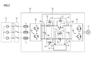
- FIG. 2 a frequency converter 26 is shown, which is connected via a main contactor 24 to the mains phases R, S, T of a network 12. To the frequency converter 26, an electric machine 14 is connected.
- the network 12, the main contactor 24 and the electric machine 14, which in FIG. 2 are shown correspond to the in FIG. 1 with shown elements the same reference numerals. These elements are therefore not explained again here.
- a feed unit 28 is connected via a DC link 30 to a converter 32.
- the feed unit 28 may be configured in a known manner. In the example shown, it has three half-bridges for rectifying the AC voltages applied between the network phases R, S, T, of which in FIG. 2 the sake of clarity, only a half-bridge 34 is shown without further interconnection elements.
- the feed unit 28 can also be operated as an inverter for feeding electrical energy into the network 12.
- the inverter 32 may also be configured in a known manner. In the present example it comprises three half-bridges, of which in FIG. 2 only a half-bridge 36 (without interconnection elements) is shown.
- the inverter 32 can be operated here as an AC and rectifier.
- the supply unit 28 are upstream of the network side chokes L 1, L 2 , L 3 , which are formed as Kommut istsinduktditeen.
- An inverter-side part 38 of the intermediate circuit 30 and a supply-side part 40 are interconnected via a switching device 42.
- a control input G 1 of a semiconductor switch S 1 and a control input G 2 of a semiconductor switch S 2 of the switching device 42 are coupled to a control device 44.
- the switch S 1 is a SiC-MOSFET and the switch S 2 is an IGBT in Si technology.
- the switch S 1 may also be provided as a cascode circuit of a SiC-JFET and a MOSFET.
- the two switches S 1 and S 2 can at the Switching device 42 may also be arranged in the respective other line branch Z 1 or Z 2 .
- the switching device 42 is capable of blocking voltage at a chained mains voltage up to over 1200 V and can also be switched under current flow.
- Diodes D 1 and D 2 of the switching device 42 allow in a generator operation of the electric machine 14 a current flow from the inverter 32 to the feed unit 28. If a parasitic diode of the switch S 1 or S 2 has a sufficiently large current carrying capacity, can on the corresponding diode D. 1 and D 2 are also dispensed with.
- a capacitance of the intermediate circuit capacitor 46 may be greater than 1 mF in the example shown.
- line branches Z 1 and Z 2 of the intermediate circuit are capacitively coupled to one another via a commutation capacitor 48.
- the commutation capacitor 48 may be a ceramic or foil capacitor.
- the capacitance of the commutation capacitor 48 is less than 5 ⁇ F in this example. However, it is generally selected as a function of a total power that can be conducted via the frequency converter 26, wherein it is also preferably less than ten percent of the capacitance of the intermediate circuit capacitor 46.
- a common-mode choke 50 with freewheeling diodes 52, 54 is installed in the converter-side part 38.
- the common mode choke 50 is connected between the commutation capacitor 48 and the DC link capacitor 46.
- frequency converter 26 is both a controlled pre-charging of the intermediate circuit capacitor 46 in the precharge phase as well as a rapid separation of the converter side portion 38 of the intermediate circuit 30 from the network 12 for canceling an operating phase possible.
- the switch S 2 together with the switch S 1 makes it possible to reliably disconnect the DC link 30 even in the event of an earth fault.
- the switch S 1 (SiC-MOSFET) does not have to be switched simultaneously with the switch S 2 when the intermediate circuit capacitor 46 is precharged. This opens up the possibility of designing both switches according to different criteria.
- a semiconductor switch can be selected as the switch S 2 , which has the lowest possible volume resistance in the conductive state, such as in FIG. 2 shown Si transistor. The switch S 2 may then be continuously switched to a conducting state during the precharge phase.
- the precharging of the intermediate circuit 30 can be performed clocked.
- the two switches S 1 and S 2 are switched to a blocking state, so that the converter-side part 38 of the intermediate circuit 30 is electrically isolated from the supply unit 28.
- the main contactor 24 is closed, so that the feed unit 28 generates a rectified voltage at its intermediate-circuit side terminal.
- the current consumption of the commutation capacitor 48 is limited only by the inductance of the inductors L 1 , L 2 , L 3 and the network inductance. Since the commutation capacitance of the commutation capacitor 48 is relatively small, it is quickly charged to the rectification value of the mains voltage. Thus, despite the hard, ie abrupt, connection of the commutation capacitor 48 to the network 12, the average current strength does not increase over a critical value for the feed unit 28.
- a clocked control signal is generated by the control unit 44 at the control terminal G 1 , whose pulse-pause times can be selected as needed and the size of the DC link capacitance.
- the switch S 2 is switched to a permanently conductive state.
- the switch S 1 is pulsed or intermittently switched to a conductive state, so that electric charge is transferred from the Kommut réelleskondensator 48 via the switching device 42 in the DC link capacitor 46. Charge can be transferred until the two capacitors 46, 48 have the same voltages. This transfer is referred to below as the transfer cycle.
- the transient current flowing in this case is limited by the common mode choke 50. It is thus possible to switch the switch S 1 completely conductive. Due to the limited recharging current, the power dissipated in switching device 42 remains so low that switches S 1 and S 2 are not damaged. If sufficiently large (parasitic) inductances and resistances are present in the frequency converter 26, a common-mode choke can also be dispensed with.
- the first transfer cycle is ended by the switch S 1 being switched back to the blocking state.
- the commutation capacitor 48 is thereby charged again with electrical energy from the network 12 via diodes of the half-bridges of the feed unit 28 (ie also the half-bridge 34), ie a second transfer cycle is started.
- the switch S 1 for the transfer of electrical energy can also be operated as a controlled current source.
- the switch S 1 for the transfer of electrical energy is turned on only in part, so that although it is in a conductive state, but the voltage dropping above it is so great that the load current is limited.
- it can also be provided to operate both switches S 1 and S 2 as controlled current sources.
- the frequency converter 26 By operating at least one of the switches S 1 and S 2 as controlled current sources, it is also possible to use the frequency converter 26 without the common mode choke 50. It may also be provided to clock this one of the switches and operate the other as a controlled power source.
- control signals for the control terminals G 1 and G 2 may have a fixed course. But it is also a regulated operation possible in which the control signals, eg. B. the pulse-pause times in the clocked operation, are generated in dependence on a measured variable. For example, a state of charge of the DC link capacitor 46 can be monitored by means of a voltage sensor.
- the control device 44 receives measurement signals from current transformers (not shown) by which a current intensity of a current flowing to the electric machine 14 is detected. The controller 44 monitors this current. Upon detection of an earth fault current in the electric machine 14, both switches S 1 and S 2 are switched to a blocking state, whereby the fault current is interrupted.
- VPM is integrated in the inverter 32.
- IGBTs of the half bridges ie also of the half bridge 36, are switched to a conducting state.
- a synchronous machine prevent the conductively connected IGBT in the inverter 32 that the fed from the electric machine 14 in the inverter 32 energy charges the DC link capacitor 46 uncontrollably, so that a over the intermediate circuit capacitor 46 falling voltage above its maximum voltage increases and it is thereby destroyed.
- the VPM monitors a voltage in the DC link 30 (or in the electric machine 14 itself) via a voltage sensor (not shown). If the amount of the monitored voltage exceeds a threshold, the three phases of the inverter 32 are short-circuited by closing the IGBT. The inverter 32 then no longer emits electrical energy into the intermediate circuit 30. This also works in the event of a ground fault in which a current could flow from the electric machine 14 via the earth fault and the feed unit 28 into the DC link capacitor 46. This is prevented in the intermediate circuit 26 in that the control device 44 opens the two switches S 1 and S 2 in response to a signal of the VPM.
- the VPM can thus be operated in any faulty operating state, in particular even during a ground fault.
- the VPM integrated into the inverter 32 does not require any extra space outside the frequency converter 26, as would be the case with an external VPM.
- an internal VPM can be provided more cost-effectively, because there is no separate housing and no separate thyristors for shorting the phases necessary.
- the control device 44 and the switching device 42 in other cases of error, e.g. in the event of a short circuit, interrupting a current flow in the DC link.
- the example shows how by means of two semiconductor switches (switches S 1 and S 2 ) a triple protection for the frequency converter 26 can be provided.
- switches S 1 and S 2 switches S 1 and S 2
- a triple protection for the frequency converter 26 can be provided.
- a ground fault a safe disconnection of the intermediate circuit 30 is ensured.
- a disconnection from the network 12 is also possible.
- the average current intensity of the charging current in the intermediate circuit capacitor 46 can be limited.
Landscapes
- Engineering & Computer Science (AREA)
- Power Engineering (AREA)
- Inverter Devices (AREA)
Priority Applications (1)
| Application Number | Priority Date | Filing Date | Title |
|---|---|---|---|
| EP11165622A EP2523331A1 (fr) | 2011-05-11 | 2011-05-11 | Convertisseur de fréquence doté d'une protection de raccordement à la terre et procédé de fonctionnement de celui-ci |
Applications Claiming Priority (1)
| Application Number | Priority Date | Filing Date | Title |
|---|---|---|---|
| EP11165622A EP2523331A1 (fr) | 2011-05-11 | 2011-05-11 | Convertisseur de fréquence doté d'une protection de raccordement à la terre et procédé de fonctionnement de celui-ci |
Publications (1)
| Publication Number | Publication Date |
|---|---|
| EP2523331A1 true EP2523331A1 (fr) | 2012-11-14 |
Family
ID=44798134
Family Applications (1)
| Application Number | Title | Priority Date | Filing Date |
|---|---|---|---|
| EP11165622A Withdrawn EP2523331A1 (fr) | 2011-05-11 | 2011-05-11 | Convertisseur de fréquence doté d'une protection de raccordement à la terre et procédé de fonctionnement de celui-ci |
Country Status (1)
| Country | Link |
|---|---|
| EP (1) | EP2523331A1 (fr) |
Cited By (2)
| Publication number | Priority date | Publication date | Assignee | Title |
|---|---|---|---|---|
| CN104821541A (zh) * | 2015-05-27 | 2015-08-05 | 德力西电气有限公司 | 一种接线电路及包含该接线电路的过欠压保护器 |
| CN114175436A (zh) * | 2019-03-29 | 2022-03-11 | 西门子股份公司 | 电气网络和用于运行电气网络的方法 |
Citations (8)
| Publication number | Priority date | Publication date | Assignee | Title |
|---|---|---|---|---|
| DE9216662U1 (de) * | 1992-12-07 | 1993-01-28 | Siemens AG, 80333 München | Vorladeschaltung mit kombiniertem Überspannungsschutz für einen netzgeführten Stromrichter mit ausgangsseitigem Kondensator |
| DE19736903A1 (de) * | 1997-08-25 | 1999-03-04 | Asea Brown Boveri | Umrichter mit Gleichspannungszwischenkreis sowie Verfahren zum Betrieb eines solchen Umrichters |
| DE19739553A1 (de) | 1997-09-09 | 1999-03-11 | Siemens Ag | Vorladeschaltung für einen am Ausgang eines netzgeführten Stromrichters angeschlossenen Kondensator |
| DE19850853A1 (de) * | 1998-11-04 | 2000-05-18 | Vacuumschmelze Gmbh | Frequenzumrichter mit bedämpftem Gleichspannungszwischenkreis |
| EP1396925A2 (fr) * | 2002-09-05 | 2004-03-10 | Dr. Johannes Heidenhain GmbH | Circuit de charge pour un convertisseur |
| EP1418662A2 (fr) * | 2002-11-05 | 2004-05-12 | Power Integrations, Inc. | Procédé et dispositif pour la régulation de tension de sortie des alimentations de puissance à découpage à commande primaire |
| DE102007008765A1 (de) * | 2006-03-01 | 2007-09-06 | Rockwell Automation Technologies, Inc., Mayfield Heights | Verbesserter Stromrichter mit reduzierter Gleichtaktspannung |
| DE102010001275A1 (de) * | 2010-01-27 | 2011-02-24 | Siemens Aktiengesellschaft | Modulares Antriebssystem |
-
2011
- 2011-05-11 EP EP11165622A patent/EP2523331A1/fr not_active Withdrawn
Patent Citations (8)
| Publication number | Priority date | Publication date | Assignee | Title |
|---|---|---|---|---|
| DE9216662U1 (de) * | 1992-12-07 | 1993-01-28 | Siemens AG, 80333 München | Vorladeschaltung mit kombiniertem Überspannungsschutz für einen netzgeführten Stromrichter mit ausgangsseitigem Kondensator |
| DE19736903A1 (de) * | 1997-08-25 | 1999-03-04 | Asea Brown Boveri | Umrichter mit Gleichspannungszwischenkreis sowie Verfahren zum Betrieb eines solchen Umrichters |
| DE19739553A1 (de) | 1997-09-09 | 1999-03-11 | Siemens Ag | Vorladeschaltung für einen am Ausgang eines netzgeführten Stromrichters angeschlossenen Kondensator |
| DE19850853A1 (de) * | 1998-11-04 | 2000-05-18 | Vacuumschmelze Gmbh | Frequenzumrichter mit bedämpftem Gleichspannungszwischenkreis |
| EP1396925A2 (fr) * | 2002-09-05 | 2004-03-10 | Dr. Johannes Heidenhain GmbH | Circuit de charge pour un convertisseur |
| EP1418662A2 (fr) * | 2002-11-05 | 2004-05-12 | Power Integrations, Inc. | Procédé et dispositif pour la régulation de tension de sortie des alimentations de puissance à découpage à commande primaire |
| DE102007008765A1 (de) * | 2006-03-01 | 2007-09-06 | Rockwell Automation Technologies, Inc., Mayfield Heights | Verbesserter Stromrichter mit reduzierter Gleichtaktspannung |
| DE102010001275A1 (de) * | 2010-01-27 | 2011-02-24 | Siemens Aktiengesellschaft | Modulares Antriebssystem |
Cited By (7)
| Publication number | Priority date | Publication date | Assignee | Title |
|---|---|---|---|---|
| CN104821541A (zh) * | 2015-05-27 | 2015-08-05 | 德力西电气有限公司 | 一种接线电路及包含该接线电路的过欠压保护器 |
| CN114175436A (zh) * | 2019-03-29 | 2022-03-11 | 西门子股份公司 | 电气网络和用于运行电气网络的方法 |
| US12176163B2 (en) | 2019-03-29 | 2024-12-24 | Siemens Aktiengesellschaft | Electric grid and method for operating an electric grid |
| US12205783B2 (en) | 2019-03-29 | 2025-01-21 | Siemens Aktiengesellschaft | Apparatus for opening or closing a DC circuit, and method for automatically closing a DC circuit |
| US12217919B2 (en) | 2019-03-29 | 2025-02-04 | Siemens Aktiengesellschaft | Electrical network having fault protection control |
| US12237125B2 (en) | 2019-03-29 | 2025-02-25 | Siemens Aktiengesellschaft | Method for coordinating protective devices in a distribution grid |
| US12266489B2 (en) | 2019-03-29 | 2025-04-01 | Siemens Aktiengesellschaft | Electrical network |
Similar Documents
| Publication | Publication Date | Title |
|---|---|---|
| EP2680421B2 (fr) | Convertisseur de fréquence doté d'un condensateur de circuit intermédiaire et procédé de pré-charge de celui-ci | |
| EP2523333B1 (fr) | Procédé de fonctionnement de convertisseur de fréquence avec une précharge réglée | |
| EP3022836B1 (fr) | Protection contre les surtensions pour redresseurs actifs en cas de délestage brusque | |
| DE102015104567A1 (de) | Gesteuertes Ausschalten eines Leistungsschalters | |
| EP2523334A1 (fr) | Convertisseur de fréquence et procédé de fonctionnement de celui-ci | |
| EP2639916A2 (fr) | Circuit pour convertisseur de courant avec circuit intermédiaire, ainsi que procédé de fonctionnement d'un convertisseur de courant | |
| EP2523332A1 (fr) | Convertisseur de fréquence doté d'une résistance de précharge et procédé de fonctionnement de celui-ci | |
| EP2533409A1 (fr) | Convertisseur de fréquence doté d'un dispositif de limitation de courant et procédé de fonctionnement de celui-ci | |
| DE112014002475T5 (de) | Wechselrichtervorrichtung | |
| DE102013225603B4 (de) | Stromrichtervorrichtung für eine Ein- oder Mehrachsanordnung und Betriebsverfahren | |
| DE102015013875B4 (de) | Wechselrichter für eine elektrische Maschine, elektrische Antriebseinrichtung für ein Kraftfahrzeug sowie Verfahren zum Betreiben eines Wechselrichters | |
| EP3379675A1 (fr) | Construction optimisée d'un système de tension continue et procédé lors d'une panne du réseau d'alimentation | |
| EP3138192B1 (fr) | Dispositif permettant de faire fonctionner un redresseur, en particulier un pont redresseur semi-commandé, et procédé permettant de faire fonctionner un redresseur | |
| EP2733837A1 (fr) | Convertisseur | |
| EP2523331A1 (fr) | Convertisseur de fréquence doté d'une protection de raccordement à la terre et procédé de fonctionnement de celui-ci | |
| EP2198509B1 (fr) | Arrangement de pré-charge d'un condensateur de circuit intermédiaire par une tension d'alimentation | |
| WO2025163090A1 (fr) | Système d'entraînement électrique et son procédé de fonctionnement | |
| EP2648328B1 (fr) | Protection d'un convertisseur de courant avec circuit intermédiaire contre les dommages causés par la contre-tension d'une machine synchrone | |
| EP2523327B1 (fr) | Convertisseur de fréquence doté d'une protection contre les surtensions et procédé de fonctionnement de celui-ci | |
| DE102019202345B4 (de) | Fahrzeugbordnetz mit einem Akkumulator, einem Wechselspannungsanschluss und einem Gleichspannungsanschluss | |
| DE102017221635B4 (de) | Ermitteln einer Netzsystemart einer Energiequelle zum Aufladen eines elektrischen Energiespeichers | |
| DE102009008047B4 (de) | Spannungsversorgung einer Ansteuerung oberer abschaltbarer Leistungshalbleiterschalter eines netzseitigen, grundfrequenz-getakteten Stromrichters | |
| DE102014012028A1 (de) | Vorrichtung und ein Verfahren zum Laden oder Entladen eines elektrischen Energiespeichers mit beliebigen Betriebsspannungen | |
| EP2523295A1 (fr) | Convertisseur de fréquence doté d'une protection contre les surtensions pour une extinction d'urgence et procédé de fonctionnement de celui-ci | |
| EP2523323A1 (fr) | Convertisseur de fréquence doté d'une bobine d'arrêt de mode commun et procédé de fonctionnement de celui-ci |
Legal Events
| Date | Code | Title | Description |
|---|---|---|---|
| PUAI | Public reference made under article 153(3) epc to a published international application that has entered the european phase |
Free format text: ORIGINAL CODE: 0009012 |
|
| AK | Designated contracting states |
Kind code of ref document: A1 Designated state(s): AL AT BE BG CH CY CZ DE DK EE ES FI FR GB GR HR HU IE IS IT LI LT LU LV MC MK MT NL NO PL PT RO RS SE SI SK SM TR |
|
| AX | Request for extension of the european patent |
Extension state: BA ME |
|
| RAP1 | Party data changed (applicant data changed or rights of an application transferred) |
Owner name: SIEMENS AKTIENGESELLSCHAFT |
|
| 17P | Request for examination filed |
Effective date: 20130513 |
|
| 17Q | First examination report despatched |
Effective date: 20170531 |
|
| RAP1 | Party data changed (applicant data changed or rights of an application transferred) |
Owner name: SIEMENS AKTIENGESELLSCHAFT |
|
| STAA | Information on the status of an ep patent application or granted ep patent |
Free format text: STATUS: THE APPLICATION IS DEEMED TO BE WITHDRAWN |
|
| 18D | Application deemed to be withdrawn |
Effective date: 20171212 |