EP2527592A2 - Outil de retrait de tiges d'un carter de turbine à gaz - Google Patents
Outil de retrait de tiges d'un carter de turbine à gaz Download PDFInfo
- Publication number
- EP2527592A2 EP2527592A2 EP12169391A EP12169391A EP2527592A2 EP 2527592 A2 EP2527592 A2 EP 2527592A2 EP 12169391 A EP12169391 A EP 12169391A EP 12169391 A EP12169391 A EP 12169391A EP 2527592 A2 EP2527592 A2 EP 2527592A2
- Authority
- EP
- European Patent Office
- Prior art keywords
- sleeve
- rod
- flange member
- tool
- threaded
- Prior art date
- Legal status (The legal status is an assumption and is not a legal conclusion. Google has not performed a legal analysis and makes no representation as to the accuracy of the status listed.)
- Withdrawn
Links
Images
Classifications
-
- F—MECHANICAL ENGINEERING; LIGHTING; HEATING; WEAPONS; BLASTING
- F01—MACHINES OR ENGINES IN GENERAL; ENGINE PLANTS IN GENERAL; STEAM ENGINES
- F01D—NON-POSITIVE DISPLACEMENT MACHINES OR ENGINES, e.g. STEAM TURBINES
- F01D5/00—Blades; Blade-carrying members; Heating, heat-insulating, cooling or antivibration means on the blades or the members
- F01D5/005—Repairing methods or devices
-
- B—PERFORMING OPERATIONS; TRANSPORTING
- B25—HAND TOOLS; PORTABLE POWER-DRIVEN TOOLS; MANIPULATORS
- B25B—TOOLS OR BENCH DEVICES NOT OTHERWISE PROVIDED FOR, FOR FASTENING, CONNECTING, DISENGAGING, OR HOLDING
- B25B27/00—Hand tools, specially adapted for fitting together or separating parts or objects whether or not involving some deformation, not otherwise provided for
- B25B27/02—Hand tools, specially adapted for fitting together or separating parts or objects whether or not involving some deformation, not otherwise provided for for connecting objects by press fit or detaching same
- B25B27/023—Hand tools, specially adapted for fitting together or separating parts or objects whether or not involving some deformation, not otherwise provided for for connecting objects by press fit or detaching same using screws
-
- B—PERFORMING OPERATIONS; TRANSPORTING
- B25—HAND TOOLS; PORTABLE POWER-DRIVEN TOOLS; MANIPULATORS
- B25B—TOOLS OR BENCH DEVICES NOT OTHERWISE PROVIDED FOR, FOR FASTENING, CONNECTING, DISENGAGING, OR HOLDING
- B25B27/00—Hand tools, specially adapted for fitting together or separating parts or objects whether or not involving some deformation, not otherwise provided for
- B25B27/02—Hand tools, specially adapted for fitting together or separating parts or objects whether or not involving some deformation, not otherwise provided for for connecting objects by press fit or detaching same
- B25B27/04—Hand tools, specially adapted for fitting together or separating parts or objects whether or not involving some deformation, not otherwise provided for for connecting objects by press fit or detaching same inserting or withdrawing keys
-
- F—MECHANICAL ENGINEERING; LIGHTING; HEATING; WEAPONS; BLASTING
- F05—INDEXING SCHEMES RELATING TO ENGINES OR PUMPS IN VARIOUS SUBCLASSES OF CLASSES F01-F04
- F05B—INDEXING SCHEME RELATING TO WIND, SPRING, WEIGHT, INERTIA OR LIKE MOTORS, TO MACHINES OR ENGINES FOR LIQUIDS COVERED BY SUBCLASSES F03B, F03D AND F03G
- F05B2260/00—Function
- F05B2260/30—Retaining components in desired mutual position
- F05B2260/301—Retaining bolts or nuts
-
- F—MECHANICAL ENGINEERING; LIGHTING; HEATING; WEAPONS; BLASTING
- F05—INDEXING SCHEMES RELATING TO ENGINES OR PUMPS IN VARIOUS SUBCLASSES OF CLASSES F01-F04
- F05D—INDEXING SCHEME FOR ASPECTS RELATING TO NON-POSITIVE-DISPLACEMENT MACHINES OR ENGINES, GAS-TURBINES OR JET-PROPULSION PLANTS
- F05D2230/00—Manufacture
- F05D2230/70—Disassembly methods
-
- Y—GENERAL TAGGING OF NEW TECHNOLOGICAL DEVELOPMENTS; GENERAL TAGGING OF CROSS-SECTIONAL TECHNOLOGIES SPANNING OVER SEVERAL SECTIONS OF THE IPC; TECHNICAL SUBJECTS COVERED BY FORMER USPC CROSS-REFERENCE ART COLLECTIONS [XRACs] AND DIGESTS
- Y10—TECHNICAL SUBJECTS COVERED BY FORMER USPC
- Y10T—TECHNICAL SUBJECTS COVERED BY FORMER US CLASSIFICATION
- Y10T29/00—Metal working
- Y10T29/53—Means to assemble or disassemble
- Y10T29/53796—Puller or pusher means, contained force multiplying operator
- Y10T29/53839—Puller or pusher means, contained force multiplying operator having percussion or explosive operator
- Y10T29/53843—Tube, sleeve, or ferrule inserting or removing
-
- Y—GENERAL TAGGING OF NEW TECHNOLOGICAL DEVELOPMENTS; GENERAL TAGGING OF CROSS-SECTIONAL TECHNOLOGIES SPANNING OVER SEVERAL SECTIONS OF THE IPC; TECHNICAL SUBJECTS COVERED BY FORMER USPC CROSS-REFERENCE ART COLLECTIONS [XRACs] AND DIGESTS
- Y10—TECHNICAL SUBJECTS COVERED BY FORMER USPC
- Y10T—TECHNICAL SUBJECTS COVERED BY FORMER US CLASSIFICATION
- Y10T29/00—Metal working
- Y10T29/53—Means to assemble or disassemble
- Y10T29/53796—Puller or pusher means, contained force multiplying operator
- Y10T29/53848—Puller or pusher means, contained force multiplying operator having screw operator
- Y10T29/53857—Central screw, work-engagers around screw
- Y10T29/53878—Tubular or tube segment forms work-engager
- Y10T29/53883—Screw threaded work-engager
-
- Y—GENERAL TAGGING OF NEW TECHNOLOGICAL DEVELOPMENTS; GENERAL TAGGING OF CROSS-SECTIONAL TECHNOLOGIES SPANNING OVER SEVERAL SECTIONS OF THE IPC; TECHNICAL SUBJECTS COVERED BY FORMER USPC CROSS-REFERENCE ART COLLECTIONS [XRACs] AND DIGESTS
- Y10—TECHNICAL SUBJECTS COVERED BY FORMER USPC
- Y10T—TECHNICAL SUBJECTS COVERED BY FORMER US CLASSIFICATION
- Y10T29/00—Metal working
- Y10T29/53—Means to assemble or disassemble
- Y10T29/53909—Means comprising hand manipulatable tool
- Y10T29/53943—Hand gripper for direct push or pull
Definitions
- the present subject matter relates generally to a pin removal tool and, more particularly, to a tool for removing retaining pins from a gas turbine casing.
- Gas turbines typically include a compressor section, a combustion section, and a turbine section.
- the compressor section pressurizes air flowing into the turbine.
- the pressurized air discharged from the compressor section flows into the combustion section, which is generally characterized by a plurality of combustors disposed in an annular array about the axis of the engine. Air entering each combustor is mixed with fuel and combusted. Hot gases of combustion flow from the combustion liner through a transition piece to the turbine section to drive the turbine and generate power.
- the turbine section typically includes a turbine rotor having a plurality of rotor disks and a plurality of turbine buckets extending radially outwardly from and being coupled to each rotor disk for rotation therewith.
- the turbine buckets are generally designed to capture and convert the kinetic energy of the hot gases of combustion flowing through the turbine section into usable rotational energy.
- the turbine section also includes a substantially cylindrical turbine casing configured to contain the hot gases of combustion.
- the turbine casing typically supports a turbine shroud designed to encase or shroud the rotating components of the turbine rotor.
- the turbine shroud may be configured as a single component forming a continuous ring around the turbine rotor or may comprise a plurality of shroud sections or blocks that, when installed around the inner circumference of the turbine casing, abut one another so as generally define a cylindrical shape surrounding the turbine rotor.
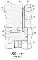
- a cross-sectional view of one embodiment of a portion of a conventional turbine casing 10 and turbine shroud 12 is illustrated in FIG. 1 .
- the turbine shroud 12 may be configured to be supported around the inner circumference of the turbine casing 10 so that an inner surface 14 of the turbine shroud 12 may be disposed adjacent to the tips of the rotating buckets of the turbine rotor (not shown).
- a shroud fit 16 may project from an inner surface 18 of the turbine casing 10.
- the turbine shroud 12 may defme a corresponding slot 20 having a size and/or shape generally corresponding to the size and/or shape of the shroud fit 16 so that the turbine shroud 12 may be installed onto the shroud fit 16 and, thus, may be radially supported against the inner surface 18 of the casing 10.
- a plurality of retaining pins 22 may be installed radially between the turbine casing 10 and the turbine shroud 12 to circumferentially and/or axially retain the turbine shroud 12 relative to the turbine casing 10.
- the turbine casing 10 may define a plurality of retaining holes 24 configured to be generally aligned with a plurality of corresponding retaining holes 26 defined in the turbine shroud 12.
- a retaining pin 22 may be radially inserted through one of the retaining holes 24 defined in the turbine casing 10 and may extend into the corresponding retaining hole 26 defined in the turbine shroud 12. As shown in FIG.
- the dimensions of the retaining holes 24, 26 and/or the retaining pin 22 may be designed such that a radially outer end 30 of the retaining pin 22 is recessed relative to an outer surface 28 of the turbine casing 10 when the pin 22 is inserted into the retaining holes 24, 26. Additionally, a threaded opening 32 may be defined in the radially outer end 30 of the retaining pin 22.
- the retaining holes 24 defmed in the turbine casing 10 may include a counter-bore 34 configured to receive a portion of a plug (not shown) for plugging the retaining holes 24 during operation of the gas turbine.
- the retaining pins 22 are often bent during installation and/or become damaged as a result of vibrations and/or relative movement occurring between the turbine casing 10 and the turbine shroud 12, thereby causing the retaining pins 22 to become stuck within the retaining holes 24, 26. Additionally, dirt and other debris may become trapped between the retaining pins 22 and the turbine casing 10 and/or the turbine shroud 10, thereby further increasing the difficulty of removing the pins 22.
- one known method for removing the retaining pins 22 includes the use of small fasteners together with heavy-duty pliers. Specifically, a small fastener is typically screwed into the threaded opening 32 defmed in each retaining pin 22. The pliers are then utilized to pull the fastener and retaining pin 22 out from the turbine casing 10.
- Another conventional method utilizes a slide-hammer-like device in order to transmit a radially outward force to the retaining pin 22.
- the present subject matter discloses a tool for removing a pin from a casing.
- the tool may generally include a rod configured to be coupled to a portion of the pin, a sleeve received on the rod and a flange member received on the sleeve.
- the flange member may be received on the sleeve such that the flange member is movable in a radial direction relative to the sleeve.
- the tool may include a collar configured to be radially engaged between the flange member and the rod when the flange member is moved radially outwardly relative to the sleeve.
- the present subject matter discloses a system including a casing and a pin extending radially within the casing.
- the system may also include the above tool, the rod thereof being coupled to a portion of the pin.
- the present subject matter is generally directed to a removal tool for removing retaining pins from a casing.
- the removal tool may generally allow for a consistent, radially outward force to be easily and efficiently applied against the retaining pin in order to pull the pin from the casing. Additionally, in several embodiments, the removal tool may be tightly secured against the retaining pin, thereby reducing the likelihood that a portion of the tool breaks off within the pin during the removal process.
- the removal tool disclosed herein will be described in the context of removing retaining pins 22 from a gas turbine casing 10 ( FIG. 1 ). However, it should be appreciated by those of ordinary skill that the removal tool may also be utilized to remove retaining pins and/or any other suitable pins from casings of differing equipment and/or from any other structure in which pins may be located.
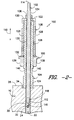
- the removal tool 100 generally comprises an assembly of different components.
- the removal tool 100 may include a rod 102 configured to be coupled to a portion of the retaining pin 22, a sleeve 104 received on the rod 102 and a flange member 106 received on the sleeve 104.
- the flange member 106 may generally be received in the sleeve 104 such that it is movable in a radial direction (indicated by arrow 110) relative to the sleeve 104.
- the removal tool 100 may include a collar 108 configured to be radially engaged against both the flange member 106 and a portion of the rod 102. As such, when the flange member 106 is moved radially outwardly relative to the sleeve 104, a radial force may be transmitted through the collar 108 and into the rod 102, thereby pushing the rod 102 radially outwardly and pulling the retaining pin 22 out from within the retaining hole 24 defmed in the turbine casing 10.
- the rod 102 of the removal tool 100 may generally comprise an elongated member extending between a first end 112 and a second end 114.
- the first and/or second end 112, 114 of the rod 102 may be configured to be attached and/or otherwise coupled to the radially outer end 30 of the retaining pin.
- the rod 102 may include a threaded projection 116 extending outwardly from its first end 112.
- the threaded projection 116 may generally be configured to be received within the threaded opening 32 defined in the retaining pin 22.
- the threaded projection 116 may have a radial length that is generally equal to or less than the radial length of the threaded opening 32.
- the threaded projection 116 may be screwed tightly within the threaded opening 32 until the first end 112 of the rod 102 is engaged against the radially outer end 30 of the retaining pin 22. Such engagement between the first end 112 of the rod 102 and the retaining pin 22 may generally prevent the threaded projection 116 from bending laterally, thereby decreasing the likelihood that the threaded projection 116 will break off within the threaded opening 32 during the removal process.
- the threaded projection 116 may comprise an integral portion of the rod 102 or a separate component configured to be separately attached to the rod 102.
- the threaded projection 116 may be formed integrally with the rod 102, such as by machining the threaded projection out of a portion of the rod 102.
- the threaded projection 116 may comprise a threaded fastener (e.g., a high strength fastener and/or any other suitable fastener) configured to be mounted to and/or otherwise attached to the first end 112 of the rod 102.
- the threaded projection 116 may be pressed into and/or attached within a corresponding opening 118 defmed through the first end 112 of the rod 102 and/or may be attached to the rod 102 using any other suitable means known in the art (e.g., by welding the threaded projection 116 to the first end 112).
- the size and/or shape of the rod 102 may generally be chosen such that at least a portion of the rod 102 (e.g., the first end 112 of the rod 102) may be inserted within the retaining hole 24.
- the first end 112 of the rod 102 may be sized and/or shaped similarly to the size and/or shape of the retaining pin 22, such as by having a generally cylindrical shape and/or by defining a diameter generally equal to the diameter of the retaining pin 22.
- the rod 102 may be configured to be coupled to the radially outer end 30 of the retaining pin 22 using any other suitable attachment method known the art.
- the first or second end 112, 114 of the rod 102 may be welded to the radially outer end 30 of the retaining pin 22.
- the sleeve 104 of the removal tool 100 may generally be configured to be received onto at least a portion of the rod 102.
- the sleeve 104 may have a hollow or tubular configuration and may define a through-passage 120 extending along the entire radial length of the sleeve 104 (i.e., from a top end 122 of the sleeve 104 to a bottom end 124 of the sleeve 104).
- the through-passage 122 may have any suitable size and/or shape that permits the sleeve 104 to be received on the rod 102. For example, as shown in FIG.
- the through passage 122 may have a size and/or shape generally corresponding to the size and/or shape of the rod 102 such that a loose, sliding fit is defined between the sleeve 104 and the rod 102.
- the sleeve 104 may be installed into the rod 102 at one end (e.g., the second end 114 of the rod 102) and subsequently slid and/or otherwise moved into place.
- the flange member 106 may generally be configured to be received on the sleeve 104 such that the flange member 106 is movable in a radial direction relative to the sleeve 104.
- the flange member 106 may comprise a nut (e.g., a flange nut) or any other suitable threaded member configured to be screwed onto a portion of the sleeve 104.
- a nut e.g., a flange nut
- any other suitable threaded member configured to be screwed onto a portion of the sleeve 104.
- at least a portion of an outer surface 126 of the sleeve 104 may be threaded.
- the flange member 106 may be in threaded engagement with the sleeve 104 and, thus, may be moved radially outwardly along the sleeve 104 by rotating the flange member 106 relative to the sleeve 104 in one direction and radially inwardly along the sleeve 104 by rotating the flange member 106 relative to the sleeve 104 in the other direction.
- the flange member 106 need not be configured as a nut or other suitable threaded member, but may generally comprise any suitable component capable of being displaced radially along the sleeve 104.
- the flange member 106 may simply comprise a tubular shaped member configured to be in sliding engagement with the sleeve 104.
- the flange member 106 may be displaced radially along the sleeve 104 by simply pulling and/or pushing the flange member 106 between the top and bottom ends 122, 124.
- the sleeve 104 may define a track or groove into which a portion of the flange member 106 (e.g., a corresponding tongue and/or projection) may be received. As such, the flange member 106 may be moved radially along the sleeve 104 by displacing the flange member 106 along the track or groove.
- a portion of the flange member 106 e.g., a corresponding tongue and/or projection
- the flange member 106 may be moved radially along the sleeve 104 using any suitable means known in the art.
- the flange member 106 may be moved relative to the sleeve 104 manually, such as by pushing/pulling the flange member 106 by hand and/or by using a suitable tool (e.g., a hammer) to move the flange member 106 radially relative to the sleeve 104.
- a cylinder e.g., a hydraulic, pneumatic or other suitable cylinder
- a cylinder may be coupled to the flange member 106 to facilitate relative radial motion between the sleeve 104 and the flange member 106.
- the flange member 106 may be coupled to any other suitable linear displacement mechanism (e.g., a rack and pinion, a worm gear driven device, a cam actuated device, an electro-magnetic solenoid or motor) that may be used to displace the flange member 106 relative to the sleeve 104.
- the collar 108 of the removal tool 100 may generally be configured to be radially engaged between the flange member 106 and a portion of the rod 102 so that radial forces (generated by the radially outward movement of the flange member 106 relative to the sleeve 104) may be transmitted through the collar 108 and into the rod 102.
- a first portion 128 of the collar 108 may generally be configured to be radially engaged against the flange member 106 and a second portion 130 of the collar 108 may generally be configured to be radially engage against a portion of the rod 102. For instance, as shown in FIG.
- the collar 108 may be configured to be received on the second end 114 of the rod 102 and positioned over the top end 122 of the sleeve 104 so that the first portion 128 of the collar 108 generally extends radially between the flange member 106 and the top end 122 of the sleeve 104 and the second portion 130 of the collar 108 extends circumferentially around the rod 102 at a location generally adjacent to the top end 122 of the sleeve 104.
- the collar 108 may be configured to be directly and/or indirectly engaged against the flange member 106.
- the first portion 128 of the collar 108 may configured to be in direct radial contact with the flange member 106 as it is moved radially along the sleeve 104, such as by being attached to a portion of the flange member 106 or by being in abutting engagement with a portion of the flange member 106.
- a spacer 132 or other suitable component may be disposed between the first portion 128 of the collar 108 and the flange member 106 such that any radial force applied by the flange member 106 may be transmitted through the spacer 132 and into the collar 108.
- the collar 108 may also be configured to be directly and/or indirectly engaged against the rod 102.
- the second portion 130 of the collar 108 may be configured to be in direct radial contact with the rod 102 as the flange member 106 is moved radially relative to the sleeve 104, such as by being attached to a portion of the rod 102 or by being in abutting engagement with a portion of the rod 102.
- the second portion 130 of the collar 108 may be in indirect radial contact with the rod 102. For instance, as shown in FIG.
- At least a portion of the outer surface 134 of the rod 102 may be threaded so as to receive an attachment nut 136 and/or any suitable threaded member thereon.
- the attachment nut 136 may be screwed onto the rod 102 until the nut 136 contacts the second portion 130 of the collar 108, thereby facilitating radial engagement between the collar 108 and the rod 102.
- the rod 102 may be initially coupled to the retaining pin 22 by screwing the threaded projection 116 into the corresponding threaded opening 32.
- the sleeve 104, flange member 106 and collar 108 may then be placed onto the rod 102.
- the sleeve 104, with the flange member 106 installed thereon may be installed onto the second end 114 of the rod 102 and moved radially inwardly along the rod 102 until the bottom end 124 of the sleeve 104 contacts and/or is engaged against the outer surface 28 of the turbine casing 10 (e.g., within the counter-bore 34 of the retaining hole 22).
- the collar 108 (and spacer 132) may then be installed onto the second end 114 of the rod 102 and displaced along the rod 102 and/or sleeve 104 until the first portion 128 of the collar 108 radially engages the flange member 106.
- the attachment nut 136 may then be screwed onto the rod 102 until the nut 136 engages the second portion 130 of the collar 108.
- the flange member 106 is moved radially outwardly along the sleeve 104.
- the flange member 106 may be rotated relative to the sleeve 104 to permit relative radial movement between the flange member 106 and the sleeve 104.
- the flange member 106 include one or more flattened sections 138 defined around its outer perimeter (e.g., by configuring the flange member 106 as a nut) and/or that the sleeve 104 include one or more flattened sections 140 defined around its outer perimeter to facilitate rotating the flange member 106 relative to the sleeve 104.
- the flattened sections 138, 140 may allow a maintenance worker to utilize one or more wrenches or other suitable tools to prevent the sleeve 104 from rotating while the flange member 106 is being rotated.
- the flange member 106 As the flange member 106 is moved radially outwardly along the sleeve 104, it applies a radial force against the collar 108 as the bottom end 124 of the sleeve 104 reacts against the turbine casing 10. This radial force may then be transmitted from the collar 108, through the attachment nut 136, and into the rod 102, thereby pushing the rod 102 radially outwardly relative to the sleeve 104 and pulling the retaining pin 22 radially outwardly from the turbine casing 10.
Landscapes
- Engineering & Computer Science (AREA)
- Mechanical Engineering (AREA)
- General Engineering & Computer Science (AREA)
- Structures Of Non-Positive Displacement Pumps (AREA)
- Turbine Rotor Nozzle Sealing (AREA)
- Control Of Turbines (AREA)
- Mutual Connection Of Rods And Tubes (AREA)
Applications Claiming Priority (1)
| Application Number | Priority Date | Filing Date | Title |
|---|---|---|---|
| US13/116,397 US8910357B2 (en) | 2011-05-26 | 2011-05-26 | Tool for removing pins from a gas turbine casing |
Publications (2)
| Publication Number | Publication Date |
|---|---|
| EP2527592A2 true EP2527592A2 (fr) | 2012-11-28 |
| EP2527592A3 EP2527592A3 (fr) | 2017-03-29 |
Family
ID=46168266
Family Applications (1)
| Application Number | Title | Priority Date | Filing Date |
|---|---|---|---|
| EP12169391.5A Withdrawn EP2527592A3 (fr) | 2011-05-26 | 2012-05-24 | Outil de retrait de tiges d'un carter de turbine à gaz |
Country Status (3)
| Country | Link |
|---|---|
| US (1) | US8910357B2 (fr) |
| EP (1) | EP2527592A3 (fr) |
| CN (1) | CN102794739B (fr) |
Cited By (2)
| Publication number | Priority date | Publication date | Assignee | Title |
|---|---|---|---|---|
| WO2017123446A1 (fr) * | 2016-01-11 | 2017-07-20 | General Electric Company | Outil et procédés d'enlèvement de dispositif de fixation |
| DE102019135848A1 (de) * | 2019-12-30 | 2021-07-01 | Ssw Schmack Spezialwerkzeuge Gmbh & Co. Kg | Vorrichtung zum Lösen eines Querlenkerbolzens aus einem Achsschenkel eines Kraftfahrzeuges |
Families Citing this family (9)
| Publication number | Priority date | Publication date | Assignee | Title |
|---|---|---|---|---|
| US8870171B2 (en) * | 2011-02-14 | 2014-10-28 | General Electric Company | Shroud retaining pin extraction systems and methods |
| US8910357B2 (en) * | 2011-05-26 | 2014-12-16 | General Electric Company | Tool for removing pins from a gas turbine casing |
| CN102814779A (zh) * | 2011-06-08 | 2012-12-12 | 深圳富泰宏精密工业有限公司 | 拔模器 |
| US9458731B2 (en) | 2013-03-13 | 2016-10-04 | General Electric Company | Turbine shroud cooling system |
| CN104175278A (zh) * | 2013-05-24 | 2014-12-03 | 富泰华工业(深圳)有限公司 | 拔销器 |
| US9302379B2 (en) * | 2013-08-06 | 2016-04-05 | Duane G. Shipman | Apparatus for inserting a hose coupling into a hose |
| US10717176B1 (en) * | 2018-04-05 | 2020-07-21 | Gerald L. Bowyer | Hanger pin removal tool |
| US20230093014A1 (en) * | 2021-09-21 | 2023-03-23 | Tim Fleet | Gasket Installation Guide |
| CN120516624A (zh) * | 2024-02-20 | 2025-08-22 | 通用电气技术有限公司 | 入口导向轮叶区段销移除套件 |
Family Cites Families (13)
| Publication number | Priority date | Publication date | Assignee | Title |
|---|---|---|---|---|
| US2916813A (en) * | 1955-11-18 | 1959-12-15 | Edgar E Belanger | Blind dowel extractor |
| FR2273629A1 (fr) * | 1974-06-05 | 1976-01-02 | Chrysler France | Appareil pour l'extraction des goupilles creuses |
| US4457061A (en) * | 1982-03-31 | 1984-07-03 | Dowley Manufacturing, Inc. | Harmonic balancer installer |
| IT1238059B (it) * | 1990-02-09 | 1993-06-26 | Salvagnini Transferica Spa Ora | Complesso di elementi di ancoraggio di tipo regolabile per componenti di attrezzature di bloccaggio di pezzi su un pallet di supporto |
| DE19803732C2 (de) * | 1998-01-30 | 2000-10-26 | Audi Ag | Abziehvorrichtung für einen in ein Basisteil eingepreßten Stift |
| FR2776951A1 (fr) * | 1998-04-02 | 1999-10-08 | Jean Vautrin | Dispositif extracteur de goupille |
| US7065855B2 (en) * | 2003-02-25 | 2006-06-27 | Textron Inc. | Installation tool for setting anchors |
| CN2882916Y (zh) * | 2006-03-31 | 2007-03-28 | 胡楚迁 | 抽油机曲柄销取销装置 |
| US8104751B2 (en) * | 2006-04-13 | 2012-01-31 | Schenck Rotec Gmbh | Device for holding a double clutch in a balancing machine |
| CN201006600Y (zh) * | 2006-11-22 | 2008-01-16 | 天津渤天化工有限责任公司 | 轴承拆卸装置 |
| CN201128132Y (zh) * | 2007-12-12 | 2008-10-08 | 中国第一汽车集团公司 | 专用拔销器 |
| US8146221B2 (en) * | 2008-10-22 | 2012-04-03 | Jung-Liang Hung | Hydraulic tool |
| US8910357B2 (en) * | 2011-05-26 | 2014-12-16 | General Electric Company | Tool for removing pins from a gas turbine casing |
-
2011
- 2011-05-26 US US13/116,397 patent/US8910357B2/en not_active Expired - Fee Related
-
2012
- 2012-05-24 EP EP12169391.5A patent/EP2527592A3/fr not_active Withdrawn
- 2012-05-25 CN CN201210182918.3A patent/CN102794739B/zh not_active Expired - Fee Related
Non-Patent Citations (1)
| Title |
|---|
| None |
Cited By (4)
| Publication number | Priority date | Publication date | Assignee | Title |
|---|---|---|---|---|
| WO2017123446A1 (fr) * | 2016-01-11 | 2017-07-20 | General Electric Company | Outil et procédés d'enlèvement de dispositif de fixation |
| US11123848B2 (en) | 2016-01-11 | 2021-09-21 | General Electric Company | Fastener removal tools and methods |
| DE102019135848A1 (de) * | 2019-12-30 | 2021-07-01 | Ssw Schmack Spezialwerkzeuge Gmbh & Co. Kg | Vorrichtung zum Lösen eines Querlenkerbolzens aus einem Achsschenkel eines Kraftfahrzeuges |
| DE102019135848B4 (de) | 2019-12-30 | 2022-09-29 | Ssw Schmack Spezialwerkzeuge Gmbh & Co. Kg | Vorrichtung zum Lösen eines Querlenkerbolzens aus einem Achsschenkel eines Kraftfahrzeuges |
Also Published As
| Publication number | Publication date |
|---|---|
| US8910357B2 (en) | 2014-12-16 |
| CN102794739B (zh) | 2016-06-08 |
| CN102794739A (zh) | 2012-11-28 |
| EP2527592A3 (fr) | 2017-03-29 |
| US20120301291A1 (en) | 2012-11-29 |
Similar Documents
| Publication | Publication Date | Title |
|---|---|---|
| US8910357B2 (en) | Tool for removing pins from a gas turbine casing | |
| US8713776B2 (en) | System and tool for installing combustion liners | |
| US8782865B2 (en) | Combustor liner and flow sleeve tool | |
| US8276273B2 (en) | Method for removing blade ring and member for removing blade ring | |
| US8776347B2 (en) | Tool for rotor assembly and disassembly | |
| EP3327250B1 (fr) | Installation ou dépose d'aube de turbine à l'embase de l'aube de turbine | |
| EP3225779A1 (fr) | Outil d'extraction | |
| EP3330040B1 (fr) | Outil pour chemise de chambre de combustion | |
| EP3402630B1 (fr) | Outil et procédés d'enlèvement de dispositif de fixation | |
| JP2022505311A (ja) | 損傷したねじ山を修繕するための方法および工具 | |
| WO2014105668A1 (fr) | Structure d'attachement de nez de moteur de turbine à gaz | |
| EP3255345A1 (fr) | Outil d'installation et système d'assemblage d'un dispositif de combustion de turbine à gaz | |
| WO2015060734A1 (fr) | Outil et procédé de retrait de segment de tuyère | |
| US10533751B2 (en) | Combustion can maintenance apparatus and method | |
| EP2843313A1 (fr) | Procédé pour enlever le couvercle d'extrémité d'un ensemble de couvercle de chambre de combustion | |
| EP2835497A2 (fr) | Appareil de remplacement de composant de turbine à distance et procédé de remplacement d'un tel composant | |
| EP2913483B1 (fr) | Procédé pour retirer un godet de rotor d'une roue de rotor d'une turbomachine | |
| US20160230599A1 (en) | Flangeless conical sleeve and method of repair |
Legal Events
| Date | Code | Title | Description |
|---|---|---|---|
| PUAI | Public reference made under article 153(3) epc to a published international application that has entered the european phase |
Free format text: ORIGINAL CODE: 0009012 |
|
| AK | Designated contracting states |
Kind code of ref document: A2 Designated state(s): AL AT BE BG CH CY CZ DE DK EE ES FI FR GB GR HR HU IE IS IT LI LT LU LV MC MK MT NL NO PL PT RO RS SE SI SK SM TR |
|
| AX | Request for extension of the european patent |
Extension state: BA ME |
|
| PUAL | Search report despatched |
Free format text: ORIGINAL CODE: 0009013 |
|
| AK | Designated contracting states |
Kind code of ref document: A3 Designated state(s): AL AT BE BG CH CY CZ DE DK EE ES FI FR GB GR HR HU IE IS IT LI LT LU LV MC MK MT NL NO PL PT RO RS SE SI SK SM TR |
|
| AX | Request for extension of the european patent |
Extension state: BA ME |
|
| RIC1 | Information provided on ipc code assigned before grant |
Ipc: F01D 5/00 20060101AFI20170221BHEP |
|
| STAA | Information on the status of an ep patent application or granted ep patent |
Free format text: STATUS: THE APPLICATION IS DEEMED TO BE WITHDRAWN |
|
| 18D | Application deemed to be withdrawn |
Effective date: 20170930 |