EP2527745A1 - Dispositif de chauffage - Google Patents
Dispositif de chauffage Download PDFInfo
- Publication number
- EP2527745A1 EP2527745A1 EP11732818A EP11732818A EP2527745A1 EP 2527745 A1 EP2527745 A1 EP 2527745A1 EP 11732818 A EP11732818 A EP 11732818A EP 11732818 A EP11732818 A EP 11732818A EP 2527745 A1 EP2527745 A1 EP 2527745A1
- Authority
- EP
- European Patent Office
- Prior art keywords
- heating
- flow
- room
- path formation
- blow
- Prior art date
- Legal status (The legal status is an assumption and is not a legal conclusion. Google has not performed a legal analysis and makes no representation as to the accuracy of the status listed.)
- Withdrawn
Links
- 238000010438 heat treatment Methods 0.000 title claims abstract description 835
- 230000015572 biosynthetic process Effects 0.000 claims abstract description 436
- 238000005192 partition Methods 0.000 claims abstract description 142
- 238000007664 blowing Methods 0.000 claims abstract description 9
- 238000010411 cooking Methods 0.000 description 93
- 230000008859 change Effects 0.000 description 34
- 230000004087 circulation Effects 0.000 description 19
- 230000002093 peripheral effect Effects 0.000 description 17
- 230000007246 mechanism Effects 0.000 description 16
- 230000006870 function Effects 0.000 description 13
- 230000017525 heat dissipation Effects 0.000 description 9
- 238000003466 welding Methods 0.000 description 9
- 239000002184 metal Substances 0.000 description 8
- 238000000034 method Methods 0.000 description 7
- 238000003860 storage Methods 0.000 description 7
- 238000010586 diagram Methods 0.000 description 6
- 230000001965 increasing effect Effects 0.000 description 6
- 239000000463 material Substances 0.000 description 6
- 235000014510 cooky Nutrition 0.000 description 5
- 230000009467 reduction Effects 0.000 description 5
- 239000004615 ingredient Substances 0.000 description 4
- 230000008569 process Effects 0.000 description 4
- 241000287828 Gallus gallus Species 0.000 description 2
- 230000000903 blocking effect Effects 0.000 description 2
- 230000015556 catabolic process Effects 0.000 description 2
- 235000013330 chicken meat Nutrition 0.000 description 2
- 238000006731 degradation reaction Methods 0.000 description 2
- 230000002401 inhibitory effect Effects 0.000 description 2
- 238000005259 measurement Methods 0.000 description 2
- 239000007769 metal material Substances 0.000 description 2
- 229910001285 shape-memory alloy Inorganic materials 0.000 description 2
- 230000007480 spreading Effects 0.000 description 2
- 238000003892 spreading Methods 0.000 description 2
- 101001109518 Homo sapiens N-acetylneuraminate lyase Proteins 0.000 description 1
- 102100022686 N-acetylneuraminate lyase Human genes 0.000 description 1
- 238000005842 biochemical reaction Methods 0.000 description 1
- 239000000919 ceramic Substances 0.000 description 1
- 239000003086 colorant Substances 0.000 description 1
- 238000009826 distribution Methods 0.000 description 1
- 238000001035 drying Methods 0.000 description 1
- 230000000694 effects Effects 0.000 description 1
- 230000006872 improvement Effects 0.000 description 1
- 230000001939 inductive effect Effects 0.000 description 1
- 239000004065 semiconductor Substances 0.000 description 1
- 238000005245 sintering Methods 0.000 description 1
Images







Classifications
-
- F—MECHANICAL ENGINEERING; LIGHTING; HEATING; WEAPONS; BLASTING
- F24—HEATING; RANGES; VENTILATING
- F24C—DOMESTIC STOVES OR RANGES ; DETAILS OF DOMESTIC STOVES OR RANGES, OF GENERAL APPLICATION
- F24C15/00—Details
- F24C15/32—Arrangements of ducts for hot gases, e.g. in or around baking ovens
- F24C15/322—Arrangements of ducts for hot gases, e.g. in or around baking ovens with forced circulation
- F24C15/325—Arrangements of ducts for hot gases, e.g. in or around baking ovens with forced circulation electrically-heated
Definitions
- the present invention relates to heating devices which heat objects to be heated within a heating room, using convection heating systems for creating hot air flows with a blower fan and a heater and, further, causing convection of created hot air flows into the heating room.
- a heating cooker as a heating device of this type has been generally provided with a hot-air-flow circulation mechanism including a blower fan and a heater, in the rear of a rear wall, which forms a rear surface of a heating room for placing objects to be heated.
- the hot-air-flow circulation mechanism is structured to suck air within the heating room, with the blower fan, through a suction port provided in the rear wall of the heating room, further to blow them onto the heater and to blow off hot air flows having been heated by the heater into the heating room through blow-off ports provided in the rear wall of the heating room.
- the heating cooker including the hot-air-flow circulation mechanism is adapted to perform cooking for objects to be heated within the heating room, using a convection heating system utilizing circulations of hot air flows within the heating room.
- heating cookers adapted to supply hot air flows into a heating room through blow-off ports using airflow direction plates provided in a hot-air-flow circulation mechanism, in order to uniformize the temperature distribution within the heating room (refer to Japanese Examined Patent Application Publication No. H7-111256 (Patent Literature 1), for example). Further, there have been heating cookers adapted to collect portions of hot air flows from a blower fan and to cause hot air flows from blow-off ports to spread over a heating room, with airflow-direction changing members provided near the blow-off ports in a hot-air-flow circulation mechanism, in order to enable heating cooking for objects to be heated without inducing heating unevenness (refer to Japanese Unexamined Patent Publication No. 2006-71124 (Patent Literature 2), for example).
- Fig. 19 is a side cross-sectional view illustrating the interior structure of a conventional heating cooker disclosed in Patent Literature 1.
- an inner casing 103 on an outer surface of a rear wall 102 which forms a rear surface of a heating room 101, wherein the rear wall 102 and the inner casing 103 constitute a casing of a hot-air-flow circulation mechanism.
- a blower fan 104 constituted by a centrifugal fan, and a substantially-annular heater 105.
- the rear wall 102 of the heating room 101 is provided, at the center thereof, with a suction port 106 formed from a plurality of punched holes.
- a plurality of blow-off ports 107 constituted by a plurality of punched holes at upper and lower positions sandwiching the suction port 106 therebetween.
- the blower fan 104 constituted by a centrifugal fan is provided inside the inner casing 103, such that it faces the suction port 106 formed at the center of the rear wall 102 of the heating room 101.
- the blower fan 104 is driven to be rotated by a motor 108 which is provided outside the inner casing 103.
- the heater 105 is a substantially-annular sheathed heater which is provided in such a way as to surround the blower fan 104.
- the conventional heating cooker illustrated in Fig. 19 is structured in such a way as to block, by airflow direction plates 109, portions of hot air flows having been blown in the centrifugal direction from the blower fan 104 and heated by the heater 105.
- the airflow direction plates 109 are provided near the blow-off ports 107 in the rear of the blow-off ports 107, in the direction of flowing of hot air flows blown from the blower fan 104.
- the airflow direction plates 109 are for the purpose of blocking and collecting portions of hot air flows from the blower fan 104 for increasing the amount of hot air flows supplied to the heating room 101 through the blow-off ports 107.
- the airflow direction plates 109 are placed, such that their plate surfaces, with which hot air flows from the blower fan 104 come into contact, are vertical with respect to the rear wall 102 and, also, are parallel with the upward and downward directions of the blower fan 104 or with the centrifugal direction with respect to the rotational center of the blower fan 104.
- a conventional heating cooker disclosed in Patent Literature 2 is also adapted to block, by airflow direction changing members, portions of hot air flows having been blown in a centrifugal direction from a blower fan and heated by a heater, thereby changing airflow directions of hot air flows supplied to a heating room through blow-off ports, similarly to the heating cooker disclosed in Patent Literature 1.
- the airflow direction changing members are placed in the rear of the blow-off ports near the blow-off ports, in the direction of flowing of hot air flows from the blower fan.
- the conventional heating cooker disclosed in Patent Literature 2 is for the purpose of blocking portions of hot air flows from the blower fan and changing the airflow directions thereof by the airflow direction changing members, for reducing unevenness of hot air flows within the heating room.
- the blower fan is driven to be rotated by the motor, so that air within the heating room is sucked through the suction port into the hot-air-flow circulation mechanism. Further, due to the rotation of the blower fan, air within the hot-air-flow circulation mechanism is blown in the centrifugal direction. Such air blown in the centrifugal direction from the blower fan is heated by the heater and, further, is supplied to the heating room through the plurality of blow-off ports (at an upper position, a lower position and side positions in the rear wall, for example). As described above, hot air flows are circulated within the heating room and within the hot-air-flow circulation mechanism, thereby performing convection heating on the object to be heated within the heating room.
- the conventional heating cookers are structured such that, after the start of convection heating, portions of hot air flows come into contact with the airflow direction plates (the airflow direction changing members) within the hot-air-flow circulation mechanism, so that hot air flows are directed in the opposite direction from the direction of the rotation of the blower fan, and hot air flows are supplied to the inside of the heating room through the blow-off ports near the airflow direction plates. Due to the provision of the plurality of airflow direction plates (the airflow direction changing members) within the hot-air-flow circulation device as described above, hot air flows are supplied to the inside of the heating room through the plurality of blow-off ports, thereby suppressing heating unevenness, namely so-called burning unevenness.
- Patent Literature 3 Japanese Unexamined Patent Publication No. H6-347041
- Patent Literature 4 Japanese Unexamined Patent Publication No. 2004-353922
- Patent Literature 1 Japanese Examined Patent Application Publication No. H7-111256
- Patent Literature 2 Japanese Unexamined Patent Publication No. 2006-71124
- Patent Literature 3 Japanese Unexamined Patent Publication No. H6-347041
- Patent Literature 4 Japanese Unexamined Patent Publication No. 2004-353922
- NPL1 Patent Company Publication "Variations of Hand Scanner” Editor Tokkyo Ichiro
- Patent Literatures 1 and 2 are structured such that air flows from the blower fan constituted by a centrifugal fan are blown in the centrifugal direction of the blower fan and, further, are flowed along the rear wall of the heating room within the hot-air-flow circulation mechanism.
- the airflow directions of air flows from the blower fan are inclined from the radial direction to the rotational direction of the blower fan along with the rotation of the blower fan, so that they have a so-called outward spiral shape.
- air flows may be blown in directions approximate to tangential directions of the rotation of the blower fan. Therefore, a larger part of hot air flows blown off from the hot-air-flow circulation device is blown through the plurality of blow-off ports in the rear wall of the heating room, in an outward spiral shape or onto the side surfaces, the ceiling surface and the bottom surface of the heating room.
- Patent Literatures 1 and 2 are structured to increase the amount of hot air flows blown through the blow-off ports, through the airflow direction plates (the airflow direction changing members) provided within the hot-air-flow circulation mechanism.
- the airflow directions of hot air flows blown off through the blow-off ports are directions approximate to substantially-tangential directions of the rotation of the blower fan.
- hot air flows blown through the blow-off ports formed at a lower position in the rear wall of the heating room are flowed along the bottom surface of the heating room
- hot air flows blown through the blow-off ports formed at an upper position in the rear wall of the heating room are flowed along the ceiling surface of the heating room and, further, hot air flows blown through the blow-off ports formed at side positions in the rear wall of the heating room are flowed along the side surfaces.
- hot air flows blown off from the hot-air-flow circulation mechanism are caused to mainly heat the wall surfaces of the heating room.
- the conventional heating cookers have had the problem that the wall surfaces of the heating room are raised to higher temperatures than that of objects to be heated within the heating room, which has increased heat dissipation losses, thereby preventing efficient heating of the objects to be heated.
- hot air flows blown off into the heating room from the hot-air-flow circulation mechanism are in substantially-tangential directions of the circle of rotations of the blower fan through the blow-off ports and, thus, may be blown off in directions perpendicular to the rotational axis of the blower fan and may be flowed along the rear wall of the heating room.
- Such conventional heating cookers have had the problem of further degradation of the heating efficiency for objects to be heated.
- Patent Literatures 3 and 4 have been structured to enable securing a control mechanism at a predetermined position within the heating room, according to the shapes and the sizes of objects to be heated and the positions at which they are housed within the heating room, for adjusting airflow directions of hot air flows within the heating room during heating operations.
- Patent Literatures 3 and 4 are not enabled to change airflow directions of hot air flows during heating operations, which has induced the problem as follows. That is, it is impossible to attain both efficient heating of objects to be heated through hot air flows being directly impinged on the objects to be heated and uniform heating of objects to be heated prone to cause burning unevenness therein.
- the present invention was made in order to overcome problems in heating devices as conventional heating cookers as described above and aims at providing a heating device capable of uniformly impinging hot air flows through blow-off ports on objects to be heated within a heating room while inhibiting hot air flows from directly heating the wall surfaces of the heating room for intensively heating the objects to be heated, thereby reducing losses due to heat dissipation through the wall surfaces of the heating room and, thus, efficiently heating the objects to be heated.
- a heating device including: a heating room for housing an object to be heated; and a heat-source room which communicates with the heating room through a suction port and a plurality of blow-off ports which are formed in a partition wall formed between the heat-source room and the heating room; wherein, inside the heat-source room, there are provided an air-blower portion for creating an air flow, a heating portion for heating the air flow, and a flow-path formation portion which forms a flow path for moving the air flow heated by the heating portion toward a surface facing the partition wall, then circulating the air flow in at least a partial space within the heat-source room and, thereafter, blowing off the air flow toward a center of the heating room through at least a single blow-off port out of the plurality of blow-off ports.
- hot air flows created by the air-blower portion and the heating portion within the heat-source room are flowed through the flow path formed by the flow-path formation portion, so that hot air flows blown off through the blow-off ports into the heating room can be flowed toward the center of the heating room.
- the flow-path formation portion is placed within an air flow path from the heating portion to the blow-off ports.
- the flow-path formation portion includes a guide surface for moving an air flow heated by the heating portion toward the surface facing the partition wall and is adapted such that the air flow moved toward the surface facing the partition wall by the guide surface is circulated in at least the partial space within the heat-source room, then is brought into contact with a surface opposite from the guide surface and, then, is blown off through the blow-off ports.
- the heating device having the aforementioned structure in the third aspect of the present invention, it is possible to uniformly impinge hot air flows through the blow-off ports on objects to be heated within the heating room and, further, it is possible to inhibit hot air flows from directly heating the wall surfaces of the heating room, thereby enabling operations for intensively heating the objects to be heated.
- the air-blower portion is constituted by a centrifugal fan which is adapted to suck air within the heating room through the suction port in the partition wall and to eject air in a centrifugal direction, and the heating portion is provided in such a way as to surround an outer periphery of the air-blower portion.
- the guide surface at least partially includes an inclined surface which is inclined at a predetermined angle with respect to an axial direction of a rotational shaft of the air-blower portion.
- the guide surface is at least partially formed from a curved surface.
- the guide surface is formed in such a way as to cover at least the blow-off ports in their entirety, with a predetermined interval interposed between the guide surface and the blow-off ports.
- the guide surface at least partially includes an inclined surface which is inclined at a predetermined angle with respect to an axial direction of a rotational shaft of the air-blower portion, whereby an air flow blown off through the blow-off ports is changed, in direction, by changing the angle of the inclined surface.
- an air flow blown off trough the blow-off ports is changed in direction by changing the rotational speed of the air-blower portion.
- the flow-path formation portion includes a longitudinal flow-path formation portion which includes a guide surface for moving an air flow heated by the heating portion toward the surface facing the partition wall and is adapted such that the air flow moved toward the surface facing the partition wall by the guide surface is circulated in at least the partial space within the heat-source room, then is brought into contact with a surface opposite from the guide surface and, then, is blown off through the blow-off ports, and a lateral flow-path formation portion which is provided downstream from the blow-off ports in the direction of flowing of an air flow created by the air-blower portion and includes a block surface placed in such a way as to block a portion of the air flow from the air-blower portion to cause it to be blown off through the blow-off ports.
- the heating device having the aforementioned structure in the tenth aspect of the present invention
- air sucked through the partition wall can be heated and, further, hot air flows can be blown off in a desired direction into the heating room through the flow path formed by the flow-path formation portion, within the heat-source room.
- This can suppress heat dissipation losses, which enables efficiently heating objects to be heated, thereby enabling speed-up for preheating of the heating room and for heating cooking.
- the flow-path formation portion includes a longitudinal flow-path formation portion which includes a guide surface for moving an air flow heated by the heating portion toward the surface facing the partition wall and is adapted such that the air flow moved toward the surface facing the partition wall by the guide surface is circulated in at least the partial space within the heat-source room, then is brought into contact with a surface opposite from the guide surface and, then, is blown off through the blow-off ports, a lateral flow-path formation portion which is provided downstream from the blow-off ports in the direction of flowing of an air flow created by the air-blower portion and includes a block surface placed in such a way as to block a portion of the air flow from the air-blower portion to cause it to be blown off through the blow-off ports, and a ceiling flow-path formation portion which includes a ceiling surface which covers the blow-off ports with a predetermined interval interposed between the ceiling surface and the blow-off ports and, further, makes the longitudinal flow-
- the heating device having the aforementioned structure in the eleventh aspect of the present invention, it is possible to certainly form the flow path for causing hot air flows created by the air-blower portion and the heating portion within the heat-source room to be blown off toward the center of the heating room through the blow-off ports.
- the guide surface in the longitudinal flow-path formation portion and the block surface in the lateral flow-path formation portion are placed around the blow-off ports, such that the guide surface and the block surface are orthogonal to each other.
- the air-blower portion is constituted by a centrifugal fan which is adapted to suck air within the heating room through the suction port in the partition wall and to eject air in a centrifugal direction, and the heating portion is provided in such a way as to surround an outer periphery of the air-blower portion.
- the heating device having the aforementioned structure in the thirteenth aspect of the present invention, air sucked through the partition wall can be certainly heated by the heating portion provided around the centrifugal fan, and hot air flows can be blown off in a desired direction into the heating room through the hot-air-flow path formed by the flow-path formation portion, within the heat-source room.
- the guide surface at least partially includes an inclined surface which is inclined at a predetermined angle with respect to an axial direction of a rotational shaft of the air-blower portion.
- the guide surface is at least partially formed from a curved surface.
- the heating device With the heating device according to the present invention, it is possible to uniformly impinge hot air flows through the blow-off ports on objects to be heated within the heating room while inhibiting hot air flows from directly heating the wall surfaces of the heating room, thereby enabling operations for intensively heating the objects to be heated. This can reduce losses due to heat dissipation through the wall surfaces of the heating room, thereby enabling efficiently heating the objects to be heated.
- heating cookers as embodiments of a heating device according to the present invention.
- the heating device according to the present invention is not limited to the structures of the heating devices which will be described in the following embodiments and is intended to include heating devices structured based on technical concepts equivalent to the technical concepts which will be described in the following embodiments and based on technical common senses in the present technical field.
- Fig. 1 is a side cross-sectional view illustrating the schematic structure of the interior of a heating cooker according to the first embodiment of the present invention.
- Fig. 2 is a plan cross-sectional view of a portion of the heating cooker illustrated in Fig. 1 , taken along the line II-II.
- Fig. 3 is a perspective view illustrating a rear-surface wall, which forms a rear wall of a heating room, in the heating cooker according to the first embodiment.
- the description will be given by assuming that its surface provided with a door which enables taking in and out objects to be heated is a front surface of the heating cooker, and the leftward and rightward directions of the heating cooker are the directions which can be viewed when it is viewed at its front surface.
- the front surface and the leftward and rightward directions will be defined as described above.
- the heating cooker according to the first embodiment includes the heating room 2 having a substantially rectangular parallelepiped structure which is formed inside a main body 1, in order to enable housing ingredients as objects 10 to be heated.
- the heating room 2 includes wall plates which are made of metal materials and form a ceiling surface, a bottom surface, a left side surface, a right side surface and a rear surface, the door 3 which is to be opened and closed for taking in and out the objects 10 to be heated, and a plurality of supporting portions 4 for supporting cooking plates 5 for placing the objects 10 to be heated.
- the supporting portions 4 are formed such that the cooking plates 5 can be placed on the supporting portions 4 in three stages.
- a magnetron 6 and an antenna 7 are installed and structured such that electromagnetic waves generated from the magnetron 6 can be radiated within the heating room 2 through the antenna 7.
- the heating room 2 having the aforementioned structure is structured such that, when the door 3 is closed, the electromagnetic waves supplied to the inside of the heating room 2 can be enclosed within the heating room 2.
- electromagnetic waves from the magnetron 6 are supplied to the heating room through the antenna
- the present invention can be also applied to structures which employ circuit structures employing semiconductor devices for creating electromagnetic waves and supplying the electromagnetic waves to the heating room and, also, can be applied to structures of oven cookers of simple convection-heating types.
- the heating cooker according to the first embodiment is provided with a heat-source room 8, adjacent to the heating room 2, in a rear-surface side in the rear of the heating room 2. Inside the heat-source room 8, there are installed a blower fan 9 constituted by a centrifugal fan, and a heater 11 constituted by a sheathed heater, which is adapted to heat air brown through rotational operations of the blower fan 9.
- the heater 11 is placed outside the blade portions of the blower fan 9, further is provided at a position displaced rearwardly from the blade portions and, further, has a substantially-square frame shape.
- the present invention is not limited to this structure, and the heater 11 can have other shapes, such as annular frame shapes, for example.
- a motor 13 as a driving power source.
- the shaft of the motor 13 penetrates a heat-source-room rear-surface wall 14 which forms the rear surface of the heat-source room 8, and the blower fan 9 as an air-blowing portion is mounted to the tip end of this shaft.
- the heat-source room 8 in which there is installed the heater 11 as a heating portion as a heat source, is separated and thermally insulated from the driving room 12 in which there is installed the motor 13 as the driving power source, by an inner case 22 including the heat-source-room rear-surface wall 14.
- partition wall 15 which forms a heating-room rear-surface wall, between the heating room 2 in which the objects 10 to be heated are housed, and the heat-source room 8 in which there are installed the blower fan 9 and the heater 11.
- the partition wall 15 spatially separates the heating room 2 and the heat-source room 8 from each other.
- the partition wall 15 which forms the heating-room rear-surface wall is provided with a suction port 16 at a position which faces the vicinity of the center of the blower fan 9 (a center area). Further, the partition wall 15 is provided with a plurality of blow-off ports 17A, 17B, 23A and 23B (see Fig. 3 ) which are constituted by a plurality of punched holes, in its areas close to the wall surfaces of the heating room 2 and outside the blower fan 9.
- the heat-source-room rear-surface wall 14 is formed to have a convex shape protruding toward the heat-source room at its center portion for providing the motor 13 in the driving room 12 in the rear of the heating cooker, rather than being formed to have a flat-plate shape.
- the heat-source-room rear-surface wall 14 is formed to have a concave shape protruding toward the driving room at its outer peripheral portion.
- the heat-source-room rear-surface wall 14 is structured such that the motor 13 is placed in the concave-portion space in the driving-room side which is formed at the center portion of the heat-source-room rear-surface wall 14.
- the heating room 2 is constituted by the left side surface 18, the right side surface 19, the bottom surface 20, the ceiling surface 21, and the partition wall 15 which forms the heating-room rear-surface wall as the rear surface, in addition to the door 3 which forms the front surface.
- the left side surface 18 and the right side surface 19 are provided with the supporting portion 4 protruding inside the heating room 2, in three stages upwardly and downwardly, substantially in parallel with the bottom surface 20, These supporting portions 4 are adapted to hold the cooking plates 5 within the heating room 2.
- the partition wall 15 which forms the rear surface of the heating room 2 has the function of separating the heating room 2 and the heat-source room 8 from each other.
- the heater 11 Inside the heat-source room 8, there are provided the heater 11, and the blower fan 9 constituted by a centrifugal fan.
- the blower fan 9 and the heater 11 are adapted to be controlled by a control portion 24 provided inside the main body 1.
- the partition wall 15 which forms the rear surface of the heating room 2 is provided, at its center portion, with the suction port 16 formed from a plurality of punched holes. Further, the partition wall 15 is provided with the plurality of blow-off ports 17A, 17B, 23A and 23B in areas around the suction port 16, such that the suction port 16 is at the center of them.
- the upper blow-off port 17A having a band shape which is formed from a plurality of punched holes, such that it is elongated in the horizontal direction, in an area from the vicinity of the end portion proximal to the left side surface 18 of the heating room 2 to a substantially-center potion of the partition wall 15.
- the lower blow-off port 17B having a band shape which is formed from a plurality of punched holes, such that it is elongated in the horizontal direction, in an area from the vicinity of the end portion proximal to the right side surface 19 of the heating room 2 to a substantially-center potion of the partition wall 15.
- the two blow-off ports formed in the partition wall 15, which are the upper blow-off port 17A and the lower blow-off port 17B, are formed point-symmetrically with respect to the center of the suction port 16.
- an arrow indicates the direction of the rotation of the blower fan 9.
- blow-off ports 23A and 23B having a band shape with a larger width which are constituted by a plurality of punched holes, in areas which are to the left and right of the suction port 16 (see Fig. 3 ).
- the partition wall 15 is provided with the left blow-off port 23A and the right blow-off port 23B which are constituted by a plurality of punched holes, similarly, at left and right positions which sandwich the suction port 16.
- the upper blow-off port 17A and the lower blow-off port 17B are formed to have a shape having a larger length in the horizontal direction and a smaller width in the vertical direction, than those of the shape of the left blow-off port 23A and the right blow-off port 23B (see Fig. 3 ).
- the heating room 2 and the heat-source room 8 communicate with each other, through the respective punched holes in the suction port 16, the upper and lower blow-off ports 17A and 17B, and the left and right blow-off ports 23A and 23B in the partition wall 15.
- the punched holes forming the suction port 16, the upper and lower blow-off ports 17A and 17B and the left and right blow-off ports 23A and 23B are formed to be groups of a plurality of holes having diameters in the range of about 2 to 5 mm, in order to prevent leakages of electromagnetic waves to the outside of the heating room 2 during heating with electromagnetic waves.
- the air-suction portion of the blower fan 9 within the heat-source room 8 is placed such that it faces the suction port 16 in the partition wall 15.
- the heater 11 Around the outer peripheral portion of the blower fan 9, which forms the air-exhaust portion, there is provided the heater 11 having a substantially-square frame shape and having a substantially-annular shape.
- the blower fan 9 is rotated and driven by the motor 13 provided outside the heat-source room 8 to generate air flows for blowing air in the centrifugal direction.
- Air flows generated are heated by the heater 11 at a position around the outer periphery of the blower fan 9 to form hot air flows and, then, are supplied to the inside of the heating room 2 through the upper and lower blow-off ports 17A and 17B and the left and right blow-off ports 23A and 23B in the partition wall 15 to perform convection heating on the objects 10 to be heated.
- the partition wall 15 forming the rear-surface wall of the heating room 2 is provided, on its the rear surface facing the heating-source room 8, with a first flow-path formation portion 30A, between the left blow-off port 23A and the suction port 16 at the center. Further, the partition wall 15 is provided, on its rear surface, with a second flow-path formation portion 30B between the right blow-off port 23B and the suction port 16 at the center.
- the first flow-path formation portion 30A and the second flow-path formation portion 30B are formed, such that they are secured at their one ends to the rear surface of the partition wall 15 and, further, are protruded, at the other ends, obliquely within the internal space of the heat-source room 8.
- the respective protruding end portions of the first flow-path formation portion 30A and the second flow-path formation portion 30B are placed, such that there is a predetermined gap between them and the heat-source-room rear-surface wall 14. Further, the first flow-path formation portion 30A and the second flow-path formation portion 30B are provided between the respective blow-off ports 23A and 23B and the heater 11 placed to surround the blower fan 9. As described above, the blower fan 9, the heater 11, the first flow-path formation portion 30A and the second flow-path formation portion 30B are provided inside the heat-source room 8 constituted by the partition wall 15 and the inner case 22 including the heat-source-room rear-surface wall 14, so that they create specific air flows within the heat-source room 8.
- the first flow-path formation portion 30A and the second flow-path formation portion 30B at positions to the left and right of the suction port 16 at the center are formed to have fixed portions 30Ab and 30Bb secured to the partition wall 15, and inclined portions 30Aa and 30Ba having guide surfaces which are inclined to be opened outwardly at an angle of about 45 degrees with respect to the flat surface (the vertical surface) formed by the partition wall 15.
- the fixed portions 30Ab and 30Bb are placed near the respective center sides of the left and right blow-off ports 23A and 23B on the rear surface, and the inclined portions 30Aa and 30Bb are obliquely extended in such a way as to cover the center sides of the left and right blow-off ports 23A and 23B.
- the fixed portions 30Ab and 30Bb are mounting portions for securing the first flow-path formation portion 30A and the second flow-path formation portion 30B to the partition wall 15, and these fixed portions 30Ab and 30Bb are secured to the partition wall 15 through staking or welding.
- the first flow-path formation potion 30A and the second flow-path formation portion 30B are formed from respective metal plates folded along straight lines. Further, the materials of the first flow-path formation potion 30A and the second flow-path formation portion 30B are not limited to metal materials and can be any materials having enough thermal resistance to maintain their shapes.
- first flow-path formation potion 30A and the second flow-path formation portion 30B will be described as being structured such that the inclined portions 30Aa and 30Bb are opened outwardly at an angle of about 45 degrees with respect to the flat surface (the vertical surface) of the partition wall 15, this angle is determined by specifications of the heating cooker. According to operation characteristics of the heating cooker, the inclined portions 30Aa and 30Ba are adapted to be opened outwardly at an angle within the range of 30 to 70 degrees with respect to the flat surface (the vertical surface) of the partition wall 15.
- the first flow-path formation portion 30A and the second flow-path formation portion 30B are formed from rectangular-shaped plate members which are folded and, further, they are placed such that the folding lines, which are straight lines, are in the vertical direction, as illustrated in Fig. 3 . Further, the first flow-path formation portion 30A and the second flow-path formation portion 30B are formed such that they are shorter than the length of the partition wall 15 in the upward and downward directions but longer than the length of the left and right blow-off ports 23A and 23B in the upward and downward directions. Further, the first flow-path formation portion 30A and the second flow-path formation portion 30B are provided along the center sides (the suction-port sides) of the left and right blow-off ports 23A and 23B.
- first flow-path formation portion 30A and the second flow-path formation portion 30B are formed such that they are longer than the length of the left and right blow-off ports 23A and 23B in the upward and downward directions
- the present invention is not limited to this structure, and they can be also formed such that they are shorter than the length of the left and right blow-off ports in the upward and downward directions, according to specifications of the heating device and the like.
- the heat-source room 8 and the driving room 12 are formed such that they have smaller depthwise sizes, in order to cause the main body 1 including the heat-source room 8 including the blower fan 9 and the heater 11 and the driving room 12 including the motor 13 to have a smaller depthwise size, while maintaining the internal capacity of the heating room 2.
- the heating cooker according to the first embodiment employs the blower fan 9 constituted by a centrifugal fan which does not degrade its air-blowing performance even though it has a smaller depthwise size, whereby the blower fan 9 can have a reduced depwthwise size at its center portion which forms the air-suction portion. Therefore, the heat-source-room rear-surface wall 14, through which the shaft of the motor 13 penetrates, has such a shape as to have a concavity toward the heating room (toward the front surface) at its portion proximal to the motor 13, wherein the motor 13 is placed inside this concavity. This results in reduction of the depthwise size of the combination of the heat-source room 8 and the driving room 12.
- the heat-source-room rear-surface wall 14 is formed as described above, and the motor 13 is placed inside the concavity in the heat-source-room rear-surface wall 14, so that the heat-source room 8 has a reduced depthwise size, at its portion proximal to the motor 13 (its center portion).
- the heat-source room 8 is made to have a larger depthwise size than that of its center portion, thereby securing a space for placing, therein, the heater 11 as a heating portion as a heat source.
- the heating cooker according to the first embodiment there are secured spaces for placing, therein, the first flow-path formation portion 30A and the second flow-path formation portion 30B at predetermined positions outside the heater 11. Particularly, there are secured air-flow paths within the heat-source room 8, which are formed by the first flow-path formation portion 30A and the second flow-path formation portion 30B. Further, inside the heat-source room 8, the heater 11 is placed, such that the position of the center of the thickness (the depthwise length) of the heater 11 is in the rear of the position of the center of the depthwise length of the blades of the blower fan 9.
- the cooking plates 5 on which objects 10 to be heated such as cookies are placed are engaged with the supporting portions 4 provided in the left and right wall surfaces of the heating room 2 and, further, these cooking plates 5 are inserted into the heating room 2.
- the cooking plates 5 are pushed until they come into contact with the partition wall 15 which forms the rear-surface wall of the heating room 2 and, then, the door 14 is closed so that the heating room 2 forms a heating space.
- Manipulations are performed on predetermined buttons in a manipulation portion (not illustrated) provided in the front surface of the main body 1, which starts oven cooking in the heating cooker.
- cooking conditions such as the heating time and the heating temperature for the objects 10 to be heated are set.
- Signals indicative of the cooking conditions having been set through the manipulation portion are inputted to the control portion 24 constituted by a microcomputer.
- the control portion 24 drives and controls the heater 11, the motor 13 and the like, based on the signals indicative of the cooking conditions.
- the rotation of the motor 13 causes the blower fan 9, which is constituted by a centrifugal fan, to start a rotating operation. Due to the rotating operation of the blower fan 9, outward air flows in a spiral shape are blown from the outer peripheral portion of the blower fan 9. Air flows blown from the blower fan 9 are heated by the heater 11 placed in such a way as to surround the outer peripheral portion of the blower fan 9 to form air flows at a higher temperature (hot air flows).
- portions of air flows from the blower fan 9 come into contact with the inclined portions 30Aa and 30Ba of the first flow-path formation portion 30A and the second flow-path formation portion 30B, which are provided at positions to the left and right of the blower fan 9, and, thus, these portions of air flows are guided thereby toward the heat-source-room rear-surface wall 14 in the rear side of the heat-source room 8.
- larger amounts of air flows are flowed toward the heater 11 placed slightly in the rear of the blower fan 9 and, thus, are heated thereby to form air flows at a higher temperature (hot air flows).
- These hot air flows are flowed in outward directions in a spiral shape along the direction of the rotation of the blower fan 9, so that the hot air flows from the upper blow-off port 17A are flowed in directions to the ceiling surface 21 and the right side surface 19 of the heating room 2, while the hot air flows from the lower blow-off port 17B are flowed in directions to the bottom surface 20 and the left side surface 18 of the heating room 2.
- the upper blow-off port 17A and the lower blow-off port 17B which are constituted by a plurality of punched holes, are formed to have a band shape elongated in the horizontal direction and, further, to be narrower and longer than the shape of the left blow-off port 23A and the right blow-off port 23B, which are formed from a plurality of punched holes (see Fig. 3 ).
- hot air flows blown in the leftward and rightward directions of the blower fan 9 are brought into contact with the first flow-path formation portion 30A and the second flow-path formation portion 30B and, thus, are guided thereby toward the heat-source-room rear-surface wall 14 which forms the rear surface of the heat-source room 8.
- the hot air flows guided to the heat-source-room rear-surface wall 14 flow along the heat-source-room rear-surface wall 14 and change their directions at the left and right end portions of the heat-source room 8 and, further, are directed toward the first flow-path formation portion 30A and the second flow-path formation portion 30B, again.
- the hot air flows are guided by the rear surfaces of the first flow-path formation portion 30A and the second flow-path formation portion 30B and, then, are blown into the heating room 2 through the respective blow-off ports 23A and 23B.
- the hot air flows blown into the heating room 2 through the left and right blow-off ports 23A and 23B are flowed, within the heat-source room 8, in directions from its left and right end portions toward the center, and, therefore, they are blown toward substantially the center of the heating room 2.
- the hot air flows blown into the heating room 2 through both the left and right blow-off ports 23A and 23B are directed toward the objects 10 to be heated within the heating room 2 and, thus, are flowed in such a way as to intensively heat the objects 10 to be heated. Accordingly, the hot air flows blown into the heating room 2 through the left and right blow-off ports 23A and 23B are prevented from directly heating the wall surfaces of the heating room 2.
- the heating cooker according to the first embodiment As described above, with the heating cooker according to the first embodiment, greater parts of hot air flows blown to the inside of the heating room 2 through the left and right blow-off ports 23A and 23B from the heat-source room 8 can be concentrated on the objects 10 to be heated. As a result, with the heating cooker according to the first embodiment, it is possible to largely reduce heating losses due to intensive heating of the wall surfaces of the heating room 2 by hot air flows, which enables efficiently heating the inside of the heating room, thereby enabling efficient heating cooking for the objects to be heated. Accordingly, with the heating cooker according to the first embodiment, it is possible to reduce times for pre-heating the heating room and cooking times, thereby enabling speed-up for cooking.
- the heating cooker according to the first embodiment since the heat-source-room rear-surface wall is provided with a concavity, and the motor 13 is placed in the concavity, the driving room 12 and the heat-source room 8 which are placed in the rear of the heating room 2 are enabled to have reduced thicknesses at their portions coupled to each other.
- the structure of the heating cooker according to the first embodiment it is possible to provide a heating cooker with excellent energy-saving performance which is capable of having a reduced depthwise size over the entire device while maintaining the capacity of the heating room.
- the heating cooker according to the first embodiment has been described with respect to an example where the heater 11 is constituted by a substantially-annular shaped sheathed heater, it is also possible to employ, as a heater, a sheathed heater having a surface provided with a plurality of heat dissipation fins, which enables efficiently heating air from the blower fan 9.
- the heating cooker according to the first embodiment has been described with respect to an example where the first flow-path formation portion 30A and the second flow-path formation portion 30B are secured (adhered through staking or welding) to the partition wall 15 which forms the rear-surface wall of the heating room 2, the first flow-path formation portion 30A and the second flow-path formation portion 30B can be also adapted to be secured to other members constituting the heat-source room 8, such that they are placed at predetermined positions with respect to the left and right blow-off ports 23A and 23B.
- the heating cooker according to the second embodiment of the present invention is different from the heating cooker according to the aforementioned first embodiment, in terms of the structure of flow-path formation portions provided within a heat-source room. Accordingly, the heating cooker according to the second embodiment will be described with respect to the flow-path formation portions, in particular, and elements having the same functions and structures as those of the heating cooker according to the first embodiment will be designated by the same reference characters, and the aforementioned description of the first embodiment will be substituted for the description.
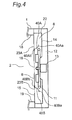
- Fig. 4 is a plan cross-sectional view illustrating the heat-source room and a driving room in the rear of a heating room in the heating cooker according to the second embodiment.
- the heating cooker according to the second embodiment is different from the heating cooker according to the first embodiment, in terms of the shapes of a first flow-path formation portion 40A and a second flow-path formation portion 40B which are provided on a partition wall 15 which forms a rear-surface wall of the heating room 2.
- the first flow-path formation portion 40A and the second flow-path formation portion 40B are formed to include respective inclined portions 40Aa and 40Ba formed from curved surfaces.
- the first flow-path formation portion 40A is constituted by the inclined portion 40Aa having a concave surface which faces a left blow-off port 23A, and a fixed portion 40Ab for securing it to the partition wall 15 which forms the rear-surface wall of the heating room 2.
- the second flow-path formation portion 40B is constituted by the inclined portion 40Ba having a concave surface which faces a right blow-off port 23B, and a fixed portion 40Bb for securing it to the partition wall 15, similarly to the first flow-path formation portion 40A.
- the heating cooker according to the second embodiment will be described with respect to an example where the first flow-path formation portion 40A and the second flow-path formation portion 40B are secured (adhered through staking or welding) to the partition wall 15, the first flow-path formation portion 40A and the second flow-path formation portion 40B can be also adapted to be secured to other members constituting the heat-source room 8 such that they are placed at predetermined positions with respect to the left and right blow-off ports 23A and 23B.
- hot air flows blown in the leftward and rightward directions of the blower fan 9 are brought into contact with the guide surface formed from the smooth curved surface (the convex surface) in the inclined portion 40Aa in the first flow-path formation portion 40A and the guide surface formed from the smooth curved surface (the convex surface) in the inclined portion 40Ba in the second flow-path formation portion 40B and, then, these hot air flows are guided thereby toward the heat-source-room rear-surface wall 14 which forms the rear-surface wall of the heat-source room.
- the hot air flows blown into the heating room 2 through the left and right blow-off ports 23A and 23B are flowed, within the heat-source room 8, in directions from its left and right end portions toward the center, and, therefore, they are blown toward substantially the center of the heating room 2 from the left and right blow-off ports 23A and 23B.
- the hot air flows blown into the heating room 2 through both the left and right blow-off ports 23A and 23B are directed toward objects 10 to be heated within the heating room 2 and, thus, are flowed in such a way as to intensively heat the objects 10 to be heated.
- first flow-path formation portion 40A and the second flow-path formation portion 40B at the fixed-portion sides of the curved surfaces in the respective inclined portions (the guide surfaces), it is possible to adjust the angle between the partition wall 15 and the end portions of these curved surfaces, which can adjust the airflow directions of hot air flows blown off into the heating room 2 through the left and right blow-off ports 23A and 23B.
- the respective inclined portions 40Aa and 40Ba in the first flow-path formation portion 40A and the second flow-path formation portion 40B are formed to have the smooth curved surfaces (the guide surfaces), so that hot air flows brown into the heating room 2 through the left and right blow-off ports 23A and 23B can be directed toward the front side of the heating room 2, more smoothly than with the heating cooker according to the aforementioned first embodiment.
- the heating cooker according to the second embodiment hot air flows blown off into the heating room 2 through the left and right blow-off ports 23A and 23B from the heat-source room 8 can be caused to smoothly change their directions and, thus, can be flowed in directions toward the front side and the center.
- the heating cooker according to the third embodiment of the present invention is different from the heating cooker according to the aforementioned first embodiment, in terms of the structure of flow-path formation portions provided within a heat-source room. Accordingly, the heating cooker according to the third embodiment will be described with respect to the flow-path formation portions, in particular, and elements having the same functions and structures as those of the heating cooker according to the first embodiment will be designated by the same reference characters, and the aforementioned description of the first embodiment will be substituted for the description.
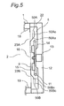
- Fig. 5 is a plan cross-sectional view illustrating the heat-source room and a driving room in the rear of a heating room in the heating cooker according to the third embodiment.
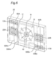
- Fig. 6 is a perspective view illustrating the interior of the heat-source room illustrated in Fig. 5 , wherein a partition wall 15 which forms a rear-surface wall of the heating room is removed.
- a first flow-path formation portion 50A and a second flow-path formation portion 50B which are provided within the heat-source room 8 include respective inclined portions 50Aa and 50Ba and respective wing portions 50Ac and 50Bc.
- the first flow-path formation portion 50A is formed in such a way as to cover the rear surface of a left blow-off port 23A with a predetermined interval interposed.
- the first flow-path formation portion 50A is constituted by the inclined portion 50Aa inclined (at about 45 degrees) with respect to the rear surface of the partition wall 15, and the wing portion 50Ac which is continuous with an extended end portion of the inclined portion 50Aa and has a surface parallel with the rear surface of the partition wall 15.
- the surfaces of the inclined portion 50Aa and the wing portion 50Ac which are faced to the heat-source-room rear-surface wall 14 form a guide surface.
- the guide surface is adapted to guide portions of hot air flows blown in the centrifugal direction from a blower fan 9 toward the heat-source-room rear-surface wall 14.
- the second flow-path formation portion 50B is formed in such a way as to cover the rear surface of a right blow-off port 23B with a predetermined interval interposed.
- the second flow-path formation portion 50B is constituted by the inclined portion 50Ba inclined (at about 45 degrees) with respect to the rear surface of the partition wall 15, and the wing portion 50Bc which is continuous with an extended end portion of the inclined portion 50Ba and has a surface parallel with the rear surface of the partition wall 15.
- the surfaces of the inclined portion 50Ba and the wing portion 50Bc which are faced to the heat-source-room rear-surface wall 14 form a guide surface.
- the wing portions 50Ac and 50Bc in the first flow-path formation portion 50A and the second flow-path formation portion 50B are placed such that there is a predetermined interval between them and the heat-source-room rear-surface wall 14, thereby forming air flow paths for passing hot air flows between the wing portions 50Ac and 50Bc and the heat-source-room rear-surface wall 14.
- the first flow-path formation portion 50A and the second flow-path formation portion 50B are extended to the upper and lower end portions of the heat-source room 8 and, thus, have the same length as the length of the heat-source-room rear-surface wall 14 in the upward and downward directions (the vertical direction). Accordingly, the first flow-path formation portion 50A and the second flow-path formation portion 50B are secured to the upper and lower end portions of an inner case 22 which forms the heat-source room 8 and, thus, are placed at predetermined positions.
- the hot air flows blown into the heating room 2 through the left and right blow-off ports 23A and 23B are flowed, within the heat-source room 8, in directions from its left and right end portions toward the center, and, therefore, they are blown toward substantially the center of the heating room 2 from the left and right blow-off ports 23A and 23B.
- the hot air flows blown into the heating room 2 through both the left and right blow-off ports 23A and 23B are directed toward objects 10 to be heated within the heating room 2 and, thus, are flowed in such a way as to intensively heat the objects 10 to be heated.
- the heating cooker according to the third embodiment hot air flows blown into the heating room 2 through the left and right blow-off ports 23A and 23B from the heat-source room 8 can be flowed intensively toward the objects 10 to be heated. As a result, it is possible to largely reduce heating losses due to intensive heating of the wall surfaces of the heating room 2 by hot air flows, which enables efficiently heating the inside of the heating room, thereby enabling efficient heating cooking for the objects to be heated. Accordingly, with the heating cooker according to the third embodiment, it is possible to reduce times for pre-heating the heating room and cooking times, thereby enabling speed-up for cooking.
- the heating cooker according to the fourth embodiment of the present invention is different from the heating cooker according to the aforementioned first embodiment, in terms of the structure of flow-path formation portions provided within a heat-source room. Accordingly, the heating cooker according to the fourth embodiment will be described with respect to the flow-path formation portions, in particular, and elements having the same functions and structures as those of the heating cooker according to the first embodiment will be designated by the same reference characters, and the aforementioned description of the first embodiment will be substituted for the description.
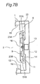
- Fig. 7A and Fig. 7B are plan cross-sectional views illustrating the heat-source room and a driving room in the rear of a heating room in the heating cooker according to the fourth embodiment.
- Fig. 7A illustrates a state where the flow-path formation portions are at a temperature equal to or lower than a predetermined temperature
- Fig. 7B illustrates a state where the flow-path formation portions are at a temperature higher than the predetermined temperature.
- Fig. 8 is a perspective view of a partition wall 15 and the like in the heating cooker according to the fourth embodiment, when it is viewed at its rear-surface side.
- first flow-path formation portion 51A between a suction port 16 formed at the center portion of the partition wall 15 and a left blow-off port 23A formed to the left of the suction port 16.
- second flow-path formation portion 51B between the suction port 16 and a right blow-off port 23B formed to the right of the suction port 16.
- the first flow-path formation portion 51A and the second flow-path formation portion 51B are formed, such that they are secured at their one ends to the rear surface of the partition wall 15 and, further, are protruded, at the other ends, obliquely within the internal space of the heat-source room 8.
- first flow-path formation portion 51A and the second flow-path formation portion 51B are placed, such that there is a predetermined interval between them and the heat-source-room rear-surface wall 14. Further, the first flow-paths formation portion 51A and the second flow-path formation portion 51B are provided between the respective blow-off ports 23A and 23B and a heater 11 placed to surround a blower fan 9.
- the first flow-path formation portion 51A and the second flow-path formation portion 51B at positions to the left and right of the suction port 16 are formed to include fixed portions 51Ab and 51Bb secured to the partition wall 15, and inclined portions 51Aa and 51Ba which are inclined outwardly with respect to the flat surface formed by the partition wall 15.
- the fixed portions 51Ab and 51Bb are placed near the center sides of the left and right blow-off ports 23A and 23B on the rear surface, and the inclined portions 51Aa and 51Ba are obliquely extended in such a way as to cover the rear-surface sides of the left and right blow-off ports 23A and 23B.
- the fixed portions 51Ab and 51Bb are mounting portions for securing the first flow-path formation portion 51A and the second flow-path formation portion 5 1 B to the partition wall 15, and these fixed portions 51Ab and 51Bb are secured to the partition wall 15 through staking or welding.
- the first flow-path formation portion 51A and the second flow-path formation portion 51B are each made of a bimetal formed from two metal plates with different thermal expansion coefficients which are attached to each other or made of a shape memory alloy.
- the first flow-path formation portion 51A and the second flow-path formation portion 51B having the aforementioned structure has the function of changing the airflow directions of hot air flows depending on the temperature of the hot air flows.
- first flow-path formation portion 51A and the second flow-path formation portion 51 B are at a temperature equal to or lower than the predetermined temperature
- the inclined portions 51Aa and 51Ba in the first flow-path formation portion 51A and the second flow-path formation portion 51B are mounted such that they are outwardly opened at an angle of about 45 degrees with respect to the partition wall 15. Since the first flow-path formation portion 51A and the second flow-path formation portion 51B are made of a bimetal formed from two metal plates with different thermal expansion coefficients which are attached to each other or made of a shape memory alloy, they have the function of changing airflow directions inside the heat-source room 8.
- the inclined portions 51Aa and 51Ba in the first flow-path formation portion 51A and the second flow-path formation portion 51B are positioned in such a way as to be inclined outwardly at an angle of about 60 degrees with respect to the partition wall 15. It is preferable that this inclination angle can be changed within the range of 30 degrees to 70 degrees.
- the first flow-path formation portion 51A and the second flow-path formation portion 51B which are provided at positions to the left and the right of the suction port 16, are formed such that they are shorter than the length of the partition wall 15 but longer than the length of the left and right blow-off ports 23A and 23B, in the vertical direction. Further, the first flow-path formation portion 51A and the second flow-path formation portion 51B are provided in such a way as to cover at least center-side areas of the left blow-off port 23A and the right blow-off port 23B.
- first flow-path formation portion 51A and the second flow-path formation portion 51 B are formed such that they are longer than the length of the left and right blow-off ports 23A and 23B in the upward and downward directions
- the present invention is not limited to this structure, and they can be also formed such that they are shorter than the length of the left and right blow-off ports in the upward and downward directions, according to specifications of the heating device, and the like.
- the heat-source room 23 and the driving room 12 are made to have smaller depthwise sizes at their portions coupled to each other, in order to cause the main body 1 including the heat-source room 8 including the blower fan 9 and the heater 11 and the driving room 12 including a motor 13 to have a smaller depthwise size, while maintaining the internal capacity of the heating room 2.
- the heating cooker according to the fourth embodiment employs the blower fan 9 constituted by a centrifugal fan which does not degrade its air-blowing performance even though it has a smaller depthwise size, whereby the blower fan 9 can have a reduced depwthwise size at its center portion which forms the air-suction portion. Therefore, the heat-source-room rear-surface wall 14, through which the shaft of the motor 13 penetrates, has such a shape as to have a concavity toward the heating room (toward the front surface) at its portion proximal to the motor 13, wherein the motor 13 is placed inside this concavity. This results in reduction of the depthwise size of the combination of the heat-source room 8 and the driving room 12.
- the heat-source-room rear-surface wall 14 is formed as described above, and the motor 13 is placed inside the concavity, so that the heat-source room 8 has a reduced depthwise size, at its portion proximal to the motor 13 (its center portion).
- the heat-source room 8 is made to have a larger depth-wise size than that of its center portion, thereby securing a space for placing the heater 11.
- the heating cooker according to the fourth embodiment there are secured spaces for placing the first flow-path formation portion 51A and the second flow-path formation portion 51B at predetermined positions outside the heater 11. Particularly, there are secured air-flow paths within the heat-source room 8 which are formed by the first flow-path formation portion 51A and the second flow-path formation portion 51B. Further, inside the heat-source room 8, the heater 11 is placed slightly in the rear of the position of the center of the depthwise length of the blades of the blower fan 9.
- heating cooker for example, in cases of performing oven cooking, cooking plates 5 on which objects 10 to be heated such as roast chickens are placed are engaged with supporting portions 4 provided in the left and right wall surfaces of the heating room 2 and, further, these cooking plates 5 are inserted into the heating room 2. The cooking plates 5 are pushed until they come into contact with the partition wall 15 and, then, a door 14 is closed so that the heating room 2 forms a heating space. Manipulations are performed on predetermined buttons in a manipulation portion (not illustrated), which is electrically connected to a control portion 24, which starts oven cooking in the heating cooker.
- cooking conditions such as the heating time and the heating temperature for the objects 10 to be heated are set.
- Signals indicative of the cooking conditions set through the manipulation portion are inputted to the control portion 24 constituted by a microcomputer.
- the control portion 24 controls the heater 11, the motor 13 and the like, based on the signals indicative of the cooking conditions.
- the blower fan 9 Due to the rotation of the motor 13, the blower fan 9 starts a rotating operation. Due to the rotating operation of the blower fan 9, air flows are blown outwardly in a spiral shape from the outer peripheral portion of the blower fan 9, which is constituted by a centrifugal fan. Air flows from the blower fan 9 are heated by the heater 11 placed in such a way as to surround the outer peripheral portion of the blower fan 9 to form air flows at a higher temperature (hot air flows).
- portions of air flows from the blower fan 9 come into contact with the inclined portions 51Aa and 51Ba of the first flow-path formation portion 51A and the second flow-path formation portion 51B, which are provided at positions to the left and right of the blower fan 9, and, thus, these portions of air flows are guided thereby toward the heat-source-room rear-surface wall 14 in the rear side of the heat-source room 8.
- Out of the air flows having been guided to the rear side of the heat-source room 8 larger amounts of air flows are flowed toward the heater 11 placed slightly in the rear of the blower fan 9 and are heated thereby to form air flows at a higher temperature (hot air flows).
- These hot air flows are flowed in outward directions in a spiral shape along the direction of the rotation of the blower fan 9, so that the hot air flows from the upper blow-off port 17A are flowed in directions to the ceiling surface 21 and the right side surface 19 of the heating room 2, while the hot air flows from the lower blow-off port 17B are flowed in directions to the bottom surface 20 and the left side surface 18 of the heating room 2.
- a temperature equal to or lower than the predetermined temperature for example, when it is equal to or lower than 150 degrees C
- hot air flows from the blower fan 9 are brought into contact with the respective inclined portions 51Aa and 51B forming the respective guide surfaces in the first flow-path formation portion 51A and the second flow-path formation portion 51B and, thus, these hot air flows are guided thereby toward the heat-source-room rear-surface wall 14 and, then, are flowed along the heat-source-room rear-surface wall 14.
- the hot air flows change their directions at the left and right end portions of the heat-source room 8 and, further, are directed toward the first flow-path formation portion 51A and the second flow-path formation portion 51B, again.
- the hot air flows are guided by the rear surfaces of the first flow-path formation portion 51A and the second flow-path formation portion 51B and, then, are blown into the heating room 2 through the respective blow-off ports 23A and 23B. Therefore, the hot air flows from the blow-off ports 23A and 23B are blown toward substantially the center of the heating room 2.
- a heating operation illustrated in Fig. 7B for example, when the first flow-path formation portion 51A and the second flow-path formation portion 51B are at a temperature higher than the predetermined temperature (for example, when it is higher than 150 degrees C), hot air flows from the blower fan 9 are brought into contact with the respective inclined portions 51Aa and 51B in the first flow-path formation portion 51A and the second flow-path formation portion 51B and, thus, these hot air flows are directed thereby toward the heat-source-room rear-surface wall 14, then change their directions at the heat-source-room rear-surface wall 14, then are guided to the first flow-path formation portion 51A and the second flow-path formation portion 5 1 B again and, then, are blown into the heating room 2 through the respective blow-off ports 23A and 23B. Therefore, the hot air flows from the blow-off ports 23A and 23B are blown into the heating room 2 substantially in parallel with the forward direction.
- the predetermined temperature for example, when it is higher than 150 degrees C
- the heating cooker according to the fourth embodiment is adapted such that, in heating operations, in a heating initial stage, hot air flows are blown into the heating room 2 through the left and right blow-off ports 23A and 23B in different directions from those in subsequent heating operation stages. This enables efficiently heating the inside of the heating room during heating operations and, further, enables heating cooking according to conditions of objects to be heated within the heating room.
- the heating cooker according to the fourth embodiment is adapted such that hot air flows blown into the heating room 2 through the left and right blow-off ports 23A and 23B are directed toward the objects 10 to be heated within the heating room 2 until a predetermined condition is satisfied, which enables intensively heating the objects 10 to be heated.
- the heating cooker according to the fourth embodiment hot air flows blown into the inside of the heating room 2 through the left and right blow-off ports 23A and 23B from the heat-source room 8 can be concentrated on the objects 10 to be heated.
- the heating cooker according to the fourth embodiment it is possible to largely reduce heating losses due to intensive heating of the wall surfaces of the heating room 2 by hot air flows, which enables efficient heating cooking for the objects to be heated.
- the first flow-path formation portion 51A and the second flow-path formation portion 51B which are made of a bimetal, are deformed due to the difference in thermal expansion coefficient between the metal plates attached to each other. Namely, as illustrated in Fig. 7B , the oblique portions 51Aa and 51Ba (the guide surfaces) of the first flow-path formation portion 51A and the second flow-path formation portion 51B are increased in inclination angle with respect to the partition wall 15 and, thus, these oblique portions 51Aa and 51Ba (the guide surfaces) are erected in the vertical direction with respect to the partition wall 15.
- the airflow directions of hot air flows blown off into the heating room 2 through the left and right blow-off ports 23A and 23B are changed from directions to the center of the heating room 2 to such directions as to surround the ingredients as the objects 10 to be heated, thereby attaining such an airflow-direction change as to prevent hot air flows from directly impinging on the objects 10 to be heated.
- the objects 10 to be heated are ingredients which tend to cause burnt-color unevenness
- the heating cooker according to the fourth embodiment due to the provision of the first flow-path formation portion 51A and the second flow-path formation portion 51B, hot air flows created by the blower fan 9 and the heater 11 within the heat-source room 8 are caused to be blown toward the center of the heating room 2 through the left and right blow-off ports 23A and 23B and, therefore, these hot air flows are prevented from directly heating the wall surfaces forming the heating room 2.
- the heating cooker according to the fourth embodiment forms an energy-saving cooking device capable of efficiently heating objects to be heated.
- the heating cooker according to the fourth embodiment in cases of objects to be heated which tend to cause burnt-color unevenness, it is possible to heat the objects to be heated in such a way as to cause hot air flows to surround the objects to be heated in airflow directions along the side wall surfaces, without causing hot air flows to directly impinge on the objects to be heated.
- the heating cooker according to the fourth embodiment can be also structured to blow off hot air flows toward the center of the heating room during pre-heating of the heating room 2 and to blow off hot air flows such that they surround objects to be heated during cooking operations with hot air flows having been raised to above a predetermined temperature.
- the heating cooker having this structure it is possible to change the airflow directions of hot air flows blown into the heating room for heating objects to be heated within the heating room, which can improve the cooking performance.
- hot air flows from the blow-off ports 23A and 23B directly impinge on the objects 10 to be heated within the heating room 2 hot air flows ejected from the blow-off ports 23A and 23B may be immediately flowed to the suction port 16 in a short-circuit manner, depending on conditions such as the temperature and the velocity of the hot air flows, which may prevent hot air flows from sufficiently spreading throughout the inside of the heating room 2.
- hot air flows from the blow-off ports 23A and 23B directly impinge on the objects 10 to be heated within the heating room 2 this may prevent the objects to be heated from being efficiently heated, depending on conditions.
- it is possible to change the airflow directions of hot air flows during heating operations which enables efficiently heating the heating room 2 and, also, enables efficiently cooking the objects 10 to be heated.
- the heating cooker according to the fifth embodiment of the present invention is different from the heating cooker according to the aforementioned first embodiment, in terms of the shape of flow-path formation portions provided within a heat-source room, the structure of a control portion and the control method. Accordingly, the heating cooker according to the fifth embodiment will be described with respect to the flow-path formation portions and the control portion, in particular, and elements having the same functions and structures as those of the heating cooker according to the first embodiment will be designated by the same reference characters, and the aforementioned description of the first embodiment will be substituted for the description.
- Fig. 9 is a plan cross-sectional view illustrating the heat-source room and a driving room in the rear of a heating room in the heating cooker according to the fifth embodiment.
- Fig. 10 is a block diagram illustrating the structure of the control portion 24 in the heating cooker according to the fifth embodiment.
- Fig. 11 is a pattern diagram illustrating operation processes for heating cooking with the heating cooker according to the fifth embodiment.
- a first flow-path formation portions 52A and a second flow-path formation portion 52B which are provided at left and right positions on a partition wall 15 are formed to cover left and right blow-off ports 23A and 23B, respectively.
- the first flow-path formation portions 52A and the second flow-path formation portion 52B are structured to include fixed portions 52Ab and 52Bb secured to the partition wall 15, and curved-surface portions 52Aa and 52Ba having concave curved surfaces faced to the respective blow-off ports 23A and 23B.
- the curved-surface portions 52Aa and 52Ba are formed to cover the rear-surface sides of the left and right blow-off ports 23A and 23B, and there is a predetermined interval between the heat-source-room rear-surface wall 14 and the protruding end portions of the curved-surface portions 52Aa and 52Ba.
- the fixed portions 52Ab and 52Bb are mounting portions for securing the first flow-path formation portion 52A and the second flow-path formation portion 52B to the partition wall 15, and these fixed portions 52Ab and 52Bb are secured to the partition wall 15 through staking or welding.
- the first flow-path formation portion 52A and the second flow-path formation portion 52B having the aforementioned structure are adapted to send portions of hot air flows having been heated by a heater 11 toward the heat-source-room rear-surface wall 14 for causing them to largely round inside the heat-source room 8. Further, the first flow-path formation portion 52A and the second flow-path formation portion 52B are adapted to guide, again, hot air flows having largely rounded inside the heat-source room 8 for causing them to be forwardly blown off toward the door 3 into the heating room 2 through the left and right blow-off ports 23A and 23B.
- the heating cooker according to the fifth embodiment it is possible to smoothly change the airflow directions of hot air flows blown off into the heating room 2 through the left and right blow-off ports 23A and 23B to directions to the front side and the center of the heating room 2, unlike the structure of the heating cooker according to the aforementioned first embodiment.
- the control portion 24 is provided with a timer portion 25, an airflow-direction determination portion 26, an operation-condition storage portion 27, and a rotational-speed control portion 28.
- the timer portion 25 is for measuring running times for heating cooking and the like.
- the airflow-direction determination portion 26 is a portion for determining and deciding airflow directions of hot air flows supplied to the inside of the heating room 2.
- the operation-condition storage portion 27 stores predetermined operation conditions of respective driving components which are electrically connected to the control portion 24, such as a motor 13, for heating cooking operations.
- the rotational-speed control portion 28 is a portion which is capable of changing the rotational speed of the motor 13 for a blower fan 9 for controlling the amount and the velocity of hot air flows created thereby for controlling the airflow directions of air flows within the heating room 2, wherein this portion constitutes an airflow-direction changing means.
- a user selects a mode of pre-heating at a predetermined temperature (for example, 250 degrees C) and starts a pre-heating operation, through button manipulations on the manipulation portion (not illustrated), without introducing the cooking plates 5.
- a predetermined temperature for example, 250 degrees C
- the timer portion 25 starts measuring the elapsed time in the pre-heating mode.
- the horizontal axis represents the time, wherein it is assumed that the pre-heating mode is started at a time Ts.
- control portion 24 starts energization of the heater 11 and the motor 13.
- the airflow-direction determination portion 26 performs a determination, and the rotational-speed control portion 28 sets the rotational speed of the motor 13 at "Medium Speed".
- the motor 13 having been set to "Medium Speed” is driven, which causes the blower fan 9 to rotate, thereby causing hot air flows to be blown in the centrifugal direction by being energized by the blower fan 9. Portions of hot air flows from the blower fan 9 are guided to the first flow-path formation portion 52A and the second flow-path formation portion 52B and, further, are blown in directions to the front side of the heating room 2 through the left and right blow-off ports 23A and 23B.
- these hot air flows blown have a not-high velocity and, therefore, are drawn by flows being sucked by the suction port 16 at the center, so that hot air flows blown through the blow-off ports 23A and 23B are directed toward the center of the heating room 2.
- the heating cooker according to the fifth embodiment is structured to notify the user of the completion of the pre-heating operation, through an annunciation sound (display light) and the like, when the temperature within the heating room 2 has reached a predetermined temperature (250 degrees C, for example).
- a predetermined temperature 250 degrees C, for example.
- the user introduces, into the heating room 2, the cooking plates 5 on which objects 10 to be heated such as roast chickens are placed and, then, he or she closes the door 3 in the heating room 2. Thereafter, the user manipulates a predetermined button in the manipulation portion (not illustrated) to start a cooking operation through oven cooking (an oven mode) with the heating cooker (the oven mode is started at a time T1).
- the timer portion 25 starts measurement of the elapsed time in the oven mode.
- the airflow-direction determination portion 26 determines operation conditions of the motor 13, based on operation conditions of the motor 13 in the oven mode, which are stored in the operation-condition storage portion 27.
- the rotational-speed control portion 28 changes and sets the rotational speed of the motor 13 to "High Speed", based on signals from the airflow-direction determination portion 26 (the high-speed operation in the oven mode is started at a time T2).
- hot air flows created by the blower fan 9 and the heater 11 within the heat-source room 8 are guided to the first flow-path formation portion 52A and the second flow-path formation portion 52B, further largely round in left and right sides within the heat-source room 8 to change their airflow directions and, then, are blown off through the respective blow-off ports 23A and 23B toward the center of the heating room 2 or in directions parallel with the left and side wall surface walls, rather than being directly blown off into the heating room 2 through the two blow-off ports 23A and 23B in the left and right sides. Accordingly, with the structure of the heating cooker according to the fifth embodiment, hot air flows blown through the left and right blow-off ports 23A and 23B are prevented from being directly directed toward the wall surfaces of the heating room 2.
- the heating cooker according to the fifth embodiment it is possible to prevent hot air flows blown through the left and right blow-off ports 23A and 23B from directly heating the wall surfaces of the heating room 2 to raise the wall surfaces of the heating room 2 to higher temperatures than that of the objects 10 to be heated.
- the heating cooker according to the fifth embodiment it is possible to reduce losses due to heat dissipation through the wall surfaces of the heating room, thereby enabling efficiently heating the objects to be heated.
- the heating cooker according to the fifth embodiment it is possible to change the airflow directions of hot air flows blown through the left and right blow-off ports 23A and 23B, through the placement of the flow-path formation portions and adjustments of the rotational speed of the motor 13, which enables heating the objects 10 to be heated in such a way as to cause hot air flows to surround the objects 10 to be heated in airflow directions parallel with the side surface walls of the heating room, without causing hot air flows from directly impinging on the objects 10 to be heated.
- the heating cooker according to the fifth embodiment it is possible to change the airflow directions for performing heating, such that hot air flows are blown off toward the center of the heating room 2 during operations for pre-heating the heating room 2, and such that hot air flows surround the objects 10 to be heated during cooking. Accordingly, with the heating cooker according to the fifth embodiment, it is possible to further improve the cooking performance.
- the heating cooker according to the fifth embodiment of the invention of the present application is adapted to change the airflow directions for heating, such that hot air flows surround the objects 10 to be heated during cooking and, therefore, has higher efficiency for heating the objects to be heated and higher cooking performance.
- the heating cooker according to the fifth embodiment is capable of easily changing the airflow directions of hot air flows blown into the heating room 2 through the left and right blow-off ports 23A and 23B during heating cooking, since it includes the airflow-direction changing means capable of changing the rotational speed of the blower fan 9 for changing the airflow directions.
- the heating cooker according to the fifth embodiment includes the control portion 24 which drives the airflow-direction changing means for controlling the airflow directions.
- the control portion 24 includes the timer portion 25 for measuring the elapsed time during heating cooking, the airflow-direction determination portion 26 for determining and deciding the airflow directions of hot air flows based on inputs from the timer portion 25, and the operation-condition storage portion 27 which stores operation conditions of the motor 13 and the like for respective set conditions.
- the control portion 24 controls the airflow directions of hot air flows blown off into the heating room 2 through the left and right blow-off ports 23A and 23B in the partition wall 15 according to heating processes.
- the heating cooker according to the fifth embodiment is capable of controlling the airflow directions of hot air flows blown off through the left and right blow-off ports 23A and 23B and, therefore, is capable of changing the airflow directions of hot air flows supplied to the inside of the heating room 2 to preferable airflow directions, according to heating processes.
- the heating cooker according to the fifth embodiment has been described as being structured to change the airflow directions with the airflow-direction determination portion 26 based on only inputs from the timer portion 25, the present invention is not limited to this structure and, for example, it is also possible to provide sensors for detecting the temperature and the burnt colors in objects 10 to be heated and to change the airflow directions of hot air flows through the blow-off ports 23A and 23B with the airflow-direction determination portion 26, based on outputs from these sensors.
- the heating cooker according to the sixth embodiment of the present invention is different from the heating cooker according to the aforementioned fifth embodiment, in terms of control methods with a control portion. Accordingly, the heating cooker according to the sixth embodiment will be described with respect to the control methods with the control portion, in particular.
- elements having the same functions and structures as those of the heating cookers according to the first to fifth embodiments will be designated by the same reference characters, and the aforementioned descriptions of the respective embodiments will be substituted for the description.
- Fig. 12 is a pattern diagram illustrating operation processes for heating cooking with the heating cooker according to the sixth embodiment.
- a user selects a pre-heating mode and starts a pre-heating operation, through button manipulations on a manipulation portion, without introducing cooking plates 5.
- a timer portion 25 starts measuring the elapsed time in the pre-heating mode.
- the horizontal axis represents the time, wherein it is assumed that the pre-heating mode is started at a time Ts.
- control portion 24 starts energization of a heater 11 and a motor 13.
- an airflow-direction determination portion 26 performs a determination, and a rotational-speed control portion 28 sets the rotational speed of the motor 13 at "Medium Speed".
- the motor 13 having been set to "Medium Speed” is driven, which causes a blower fan 9 to rotate, thereby causing air flows to be blown in the centrifugal direction by being energized by the blower fan 9. Portions of hot air flows from the blower fan 9 are guided to a first flow-path formation portion 52A and a second flow-path formation portion 52B and, further, are blown in directions to the front side of the heating room 2 through left and right blow-off ports 23A and 23B.
- these hot air flows blown have a not-high velocity and, therefore, are drawn by flows being sucked by a suction port 16 at the center, so that air flows through the blow-off ports 23A and 23B are directed toward the center of the inside of the heating room 2. Since hot air flows through the blow-off ports 23A and 23B are directed toward the center of the inside of the heating room 2 as described above, it is possible to complete the pre-heating operation with higher efficiency in a relatively-shorter time period.
- the heating cooker according to the sixth embodiment is structured to notify the user of the completion of the pre-heating operation, through an annunciation sound (display light) and the like, when the temperature within the heating room 2 has reached a predetermined temperature (180 degrees C, for example).
- a predetermined temperature 180 degrees C, for example.
- the user introduces, into the heating room 2, the cooking plates 5 on which objects 10 to be heated such as cookies are placed and, then, he or she closes the door 3 in the heating room 2. Thereafter, the user manipulates a predetermined button in the manipulation portion (not illustrated) to start a cooking operation through oven cooking (an oven mode) with the heating cooker (the oven mode is started at a time T1).
- the timer portion 25 starts measurement of the elapsed time in the oven mode.
- the airflow-direction determination portion 26 determines operation conditions of the motor 13, based on operation conditions of the motor 13 in the oven mode, which are stored in the operation-condition storage portion 27.
- hot air flows blown off through the left and right blow-off ports 23A and 23B have a sufficient velocity and, therefore, are flowed in airflow directions substantially parallel with the left and right side surface walls, without being drawn by flows being sucked by the suction port 16. Namely, hot air flows from the left and right blow-off ports 23A and 23B are caused to heat the objects 10 to be heated in such a way as to surround them, without being directly blown onto the objects 10 to be heated.
- the heating cooker having the aforementioned structure according to the sixth embodiment, it is possible to change the airflow directions of hot air flows blown off through the left and right blow-off ports 23A and 23B. Accordingly, in cases of objects 10 to be heated which tend to cause burnt-color unevenness, such as cookies, it is possible to blow off hot air flows in such a way as to flow them in parallel with the side surface walls of the heating room for causing them to surround the objects 10 to be heated for heating them, without causing hot air flows from directly impinging on the objects 10 to be heated.
- the heating cooker according to the sixth embodiment is structured to change the airflow directions for performing heating, such that hot air flows are blown off toward the center of the inside of the heating room 2 during operations for pre-heating the heating room 2, and such that hot air flows are blown off in such a way as to surround objects 10 to be heated during cooking operations. Accordingly, with the heating cooker according to the sixth embodiment, it is possible to enable both speed-up for pre-heating and improvement of the cooking performance.
- the heating cooker according to the sixth embodiment is structured to change the airflow directions of hot air flows blown off into the heating room 2 through the left and right blow-off ports 23A and 23B in the partition wall 15 according to respective heating processes during heating operations. Therefore, the heating cooker according to the sixth embodiment is capable of supplying hot air flows blown into the heating room, while changing the airflow directions to preferable airflow directions, according to heating processes.
- the heating cooker according to the seventh embodiment of the present invention is different from the heating cooker according to the aforementioned first embodiment, in terms of the structure of flow-path formation portions provided within a heat-source room. Accordingly, the heating cooker according to the seventh embodiment will be described with respect to the flow-path formation portions, in particular, and elements having the same functions and structures as those of the heating cooker according to the first embodiment will be designated by the same reference characters, and the aforementioned description of the first embodiment will be substituted for the description.
- Fig. 13 is a plan cross-sectional view illustrating the heat-source room and a driving room in the rear of a heating room in the heating cooker according to the seventh embodiment.
- the heating cooker according to the seventh embodiment is different from the heating cooker according to the first embodiment, in terms of the structure of a first flow-path formation portion 61A and a second flow-path formation portion 62 which are provided on a partition wall 15.
- Fig. 14 is a perspective view of the partition wall 15 which forms a rear-surface wall of the heating room 2 in the heating cooker according to the seventh embodiment, when it is viewed at its rear side.
- the partition wall 15 forming the rear-surface wall of the heating room 2 is provided, on its the rear surface facing the heating-source room 8, with the first flow-path formation portion 61 between a left blow-off port 23A and a suction port 16 at the center. Further, the partition wall 15 is provided, on its rear surface, with the second flow-path formation portion 62 between a right blow-off port 23B and the suction port 16 at the center.
- the first flow-path formation portion 61 and the second flow-path formation portion 62 are formed, such that they are secured at their one ends to the rear surface of the partition wall 15 and, further, are protruded, at the other ends, within the internal space of the heat-source room 8.
- the respective protruding end portions of the first flow-path formation portion 61 and the second flow-path formation portion 62 are placed, such that there is a predetermined gap between them and the heat-source-room rear-surface wall 14. Further, the first flow-path formation portion 61 and the second flow-path formation portion 62 are provided between the respective blow-off ports 23A and 23B and a heater 11 placed to surround a blower fan 9. The blower fan 9, the heater 11, the first flow-path formation portion 61 and the second flow-path formation portion 62 are provided within the internal space of the heat-source room 8 constituted by the partition wall 15 and an inner case 22 including the heat-source-room rear-surface wall 14.
- the first flow-path formation portion 61 is constituted by a longitudinal flow-path formation portion 61A and a lateral flow-path formation portion 61B
- the second flow-path formation portion 62 is constituted by a longitudinal flow-path formation portion 62A and a lateral flow-path formation portion 62B.
- the respective longitudinal flow-path formation portion 61A and 62A in the first flow-path formation portion 61 and the second flow-path formation portion 62 include fixed portions 61Ab and 62Ab secured to the partition wall 15, and inclined portions 61Aa and 61Ba which are inclined to be opened outwardly at an angle of about 45 degrees with respect to the flat surface formed by the partition wall 15.
- the fixed portions 61Ab and 62Ab are placed at positions closer to the center than the left and right blow-off ports 23A and 23B, respectively.
- the inclined portions 61Aa and 62Aa in the respective longitudinal flow-path formation portions 61A and 62A are extended in such a way as to cover the center-sides of the left and right blow-off ports 23A and 23B.
- the fixed portions 61Ab and 62Ab in the respective longitudinal flow-path formation portions 61A and 62A are mounting portions for securing the respective longitudinal flow-path formation portions 61A and 62A to the partition wall 15, and these fixed portions 61Ab and 62Ab are certainly secured to the partition wall 15 through staking or welding.
- the respective lateral flow-path formation portion 61B and 62B in the first flow-path formation portion 61 and the second flow-path formation portion 62 include fixed portions 61Bb and 62Bb secured to the partition wall 15, and block portions 61Ba and 62Ba which are orthogonal to the flat surface formed by the partition wall 15.
- the first flow-path formation portion 61 and the second flow-path formation portion 62 are each integrally formed from a folded metal plate. Further, the material of the first flow-path formation potion 61 and the second flow-path formation portion 62 is not limited to a metal and can be any material having enough thermal resistance to maintain their shapes.
- the longitudinal flow-path formation portion 61A and the lateral flow-path formation portion 61B are placed in an L shape and are formed integrally with each other.
- the first flow-path formation portion 61 formed as described above is placed along a portion of the upper side and the center side (the suction-port side) of the periphery of the left blow-off port 23A.
- the longitudinal flow-path formation portion 61A includes surfaces parallel with the normal direction (the vertical direction), while the lateral flow-path formation portion 61B includes surfaces parallel with the horizontal direction.
- the longitudinal flow-path formation portion 61A and the lateral flow-path formation portion 61B are structured to include surfaces which are parallel with the normal direction and the horizontal direction, respectively.
- the present invention is not limited to this structure, and the longitudinal flow-path formation portion and the lateral flow-path formation portion can be placed at positions which form an appropriate angle, according to specifications of this heating device, and the like.
- the longitudinal flow-path formation portion 61A is placed between the blower fan 9 and the left blow-off port 23A and is placed at a position at which hot air flows having been blown in the leftward direction from the blower fan 9 and heated by the heater 11. come into contact.
- the lateral flow-path formation portion 61B is placed downstream from the longitudinal flow-path formation portion 61A in the direction of the rotation of the blower fan 9 and proximally to the downstream-side of the left blow-off port.
- the lateral flow-path formation portion 61B is provided in such a way as to block portions of hot air flows from the blower fan 9 and to cause them to be blown off through the left blow-off port 23A.
- the second flow-path formation portion 62 is structured similarly to the first flow-path formation portion 61, wherein the longitudinal flow-path formation portion 62A and the lateral flow-path formation portion 62B are placed in an L shape and are formed integrally with each other.
- the second flow-path formation portion 62 is placed in an L shape, along a portion of the lower side and the center side of the right blow-off port 23B.
- the longitudinal flow-path formation portion 62A includes surfaces parallel with the normal direction (the vertical direction), while the lateral flow-path formation portion 62B includes surfaces parallel with the horizontal direction.
- the longitudinal flow-path formation portion 62A is placed between the blower fan 9 and the right blow-off port 23B and is placed at a position at which hot air flows having been blown in the rightward direction from the blower fan 9 and heated by the heater 11 come into contact.
- the lateral flow-path formation portion 62B is placed downstream from the longitudinal flow-path formation portion 62A in the direction of the rotation of the blower fan 9 and, thus, is provided in such a way as to block portions of hot air flows from the blower fan 9 and to cause them to be blown off through the right blow-off port 23B.
- the respective inclined portions 61Aa and 62Aa (the guide surfaces) in the first flow-path formation portion 61 and the second flow-path formation portion 62 are formed such that they are shorter than the length of the partition wall 15 in the upward and downward directions but longer than the length of the left and right blow-off ports 23A and 23B in the upward and downward directions. Further, the inclined portions 61Aa and 62Aa (the guide surfaces) are provided in such a way as to cover portions of the left and right blow-off ports 23A and 23B, respectively.
- the heat-source room 8 and the driving room 12 are made to have smaller depthwise sizes at their portions coupled to each other, in order to cause the main body 1 including the heat-source room 8 including the blower fan 9 and the heater 11 and the driving room 12 including the motor 13 to have a smaller depthwise size, while maintaining the internal capacity of the heating room 2.
- the heating cooker according to the seventh embodiment employs the blower fan 9 constituted by a centrifugal fan which does not degrade its air-blowing performance even though it has a smaller depthwise size, whereby the blower fan 9 can have a reduced depwthwise size at its center portion which forms the suction portion. Therefore, the heat-source-room rear-surface wall 14, through which the shaft of the motor 13 penetrates, has such a shape as to have a concavity toward the heating room (toward the front surface) at its portion proximal to the motor 13, wherein the motor 13 is placed inside this concavity. This results in reduction of the depthwise size of the portions of the heat-source room 8 and the driving room 12 which are coupled to each other.
- the heat-source-room rear-surface wall 14 is formed as described above, and the motor 13 is placed inside the concavity, so that the heat-source room 8 has a reduced depth-wise size, at its portion proximal to the motor 13 (its center portion).
- the heat-source room 8 is made to have a larger depthwise size than that of its center portion, thereby securing a space for placing, therein, the heater 11, the first flow-path formation portion 61 and the second flow-path formation portion 62 at predetermined positions and, further, securing air flow paths inside the heat-source room 8.
- the heater 11 is placed slightly in the rear of the position of the center of the depthwise length of the blades of the blower fan 9.
- heating cooker according to the seventh embodiment for example, in cases of performing oven cooking, cooking plates 5 on which objects 10 to be heated such as cookies are placed are engaged with supporting portions 4 provided in the left and right wall surfaces of the heating room 2 and, further, these cooking plates 5 are inserted into the heating room 2. The cooking plates 5 are pushed thereinto until they come into contact with the partition wall 15 which forms the rear-surface wall of the heating room 2 and, then, the door 14 is closed so that the heating room 2 forms a heating space. Manipulations are performed on predetermined buttons in a manipulation portion (not illustrated) provided in the front surface of the main body 1, which starts oven cooking with the heating cooker.
- cooking conditions such as the heating time and the heating temperature for the objects 10 to be heated are set.
- Signals indicative of the cooking conditions having been set through the manipulation portion are inputted to a control portion 24 constituted by a microcomputer.
- the control portion 24 drives and controls the heater 11, the motor 13 and the like, based on the signals indicative of the cooking conditions.
- the rotation of the motor 13 causes the blower fan 9 to start a rotating operation. Due to the rotating operation of the blower fan 9, outward air flows in a spiral shape are blown from the outer peripheral portion of the blower fan 9, which is constituted by a centrifugal fan. Air flows blown from the blower fan 9 are heated by the heater 11 placed in such a way as to surround the outer peripheral portion of the blower fan 9 to form air flows at a higher temperature.
- portions of air flows from the blower fan 9 come into contact with the inclined portions 61Aa and 62Aa of the first flow-path formation portion 61 and the second flow-path formation portion 62, which are provided at positions to the left and right of the blower fan 9, and, thus, these portions of air flows are guided thereby toward the heat-source-room rear-surface wall 14 in the rear side of the heat-source room 8, Out of the air flows having been guided to the rear side of the heat-source room 8, larger amounts of air flows are flowed toward the heater 11 placed slightly in the rear of the blower fan 9 and, thus, are heated thereby to form air flows at a higher temperature (hot air flows).
- the block portions 61Ba and 62Ba in the first flow-path formation portion 61 and the second flow-path formation portion 62 are adapted to block and collect portions of outward air flows in a spiral shape from the outer peripheral portion of the blower fan 9 and to guide these portions of air flows in such a way as to flow them through the left and right blow-off ports 23A and 23B. Therefore, the heating cooker according to the seventh embodiment is adapted such that larger amounts of air flows are blown off through the left and right blow-off ports 23A and 23B.
- These hot air flows are flowed in outward airflow directions in a spiral shape along the direction of the rotation of the blower fan 9, so that the hot air flows through the upper blow-off port 17A are flowed in directions to the ceiling surface 21 and the right side surface 19 of the heating room 2, while the hot air flows through the lower blow-off port 17B are flowed in directions to the bottom surface 20 and the left side surface 18 of the heating room 2.
- the hot air flows are guided by the rear surfaces (the surfaces opposite from the guide surfaces) of the inclined portions 61Aa and 62Aa of the first flow-path formation portion 61 and the second flow-path formation portion 62 and, then, are blown into the heating room 2 through the respective blow-off ports 23A and 23B.
- the hot air flows blown into the heating room 2 through the left and right blow-off ports 23A and 23B are flowed, within the heat-source room 8, in directions from its left and right end portions toward the center. Therefore, they are blown toward substantially the center of the heating room 2. Namely, the hot air flows blown into the heating room 2 through both the left and right blow-off ports 23A and 23B are directed toward the objects 10 to be heated within the heating room 2 and, thus, are flowed in such a way as to intensively heat the objects 10 to be heated.
- the heating cooker according to the seventh embodiment hot air flows blown into the heating room 2 through the left and right blow-off ports 23A and 23B from the heat-source room 8 can be flowed in such a way as to intensively heat the objects 10 to be heated.
- the heating cooker according to the seventh embodiment it is possible to largely reduce heating losses due to intensive heating of the wall surfaces of the heating room 2 by hot air flows, which enables efficiently heating the heating room 2, thereby enabling efficient heating cooking for the objects 10 to be heated.
- the heating cooker according to the eighth embodiment of the present invention is different from the heating cookers according to the aforementioned first and seventh embodiments, in terms of the structure of flow-path formation portions provided within a heat-source room. Accordingly, the heating cooker according to the eighth embodiment will be described with respect to the flow-path formation portions, in particular, and elements having the same functions and structures as those of the heating cookers according to the first and seventh embodiments will be designated by the same reference characters, and the aforementioned descriptions of the first and seventh embodiments will be substituted for the description.
- Fig. 15 is a plan cross-sectional view illustrating the heat-source room and a driving room in the rear of a heating room in the heating cooker according to the eighth embodiment.
- the heating cooker according to the eighth embodiment is different from the heating cooker according to the seventh embodiment, in terms of the shape of a first flow-path formation portion 63 and a second flow-path formation portion 64 which are provided on a partition wall 15 which forms a rear-surface wall of the heating room 2.
- the first flow-path formation portion 63 and the second flow-path formation portion 64 include respective inclined portions (guide surfaces) which are formed from curved surfaces.
- the first flow-path formation portion 63 is integrally structured to include a longitudinal flow-path formation portion 63A and a lateral flow-path formation portion 63B, similarly to the first flow-path formation portion 61 according to the aforementioned seventh embodiment illustrated in Fig. 14 .
- the longitudinal flow-path formation portion 63A includes an inclined portion having a concave surface which faces a left blow-off port 23A, and a fixed portion for securing it to a partition wall 15 which forms a rear-surface wall of the heating room 2.
- the lateral flow-path formation portion 63B includes a block portion having a horizontal surface, and a fixed portion for securing it to the partition wall 15 which forms the rear-surface wall of the heating room 2.
- the second flow-path formation portion 64 is integrally structured to include a longitudinal flow-path formation portion 64A and a lateral flow-path formation portion 64B, similarly to the first flow-path formation portion 63.
- the longitudinal flow-path formation portion 64A includes an inclined portion having a concave surface which faces a right blow-off port 23B, and a fixed portion for securing it to the partition wall 15.
- the lateral flow-path formation portion 64B includes a block portion having a horizontal surface, and a fixed portion for securing it to the partition wall 15.
- the heating cooker according to the eighth embodiment will be described with respect to an example where the first flow-path formation portion 63 and the second flow-path formation portion 64 are secured (adhered through staking or welding) to the partition wall 15, the first flow-path formation portion 63 and the second flow-path formation portion 64 can be also secured to other members constituting the heat-source room 8 and can be placed at predetermined positions with respect to the left and right blow-off ports 23A and 23B.
- hot air flows blown in the leftward and rightward directions of the blower fan 9 are brought into contact with the guide surfaces formed from the smooth curved surface (the convex surface) of the inclined portion in the first flow-path formation portion 63 and the smooth curved surface (the convex surface) of the inclined portion in the second flow-path formation portion 64 and, thus, these hot air flows are guided thereby toward the heat-source-room rear-surface wall 14.
- the hot air flows are guided by the surfaces opposite from the guide surfaces, which are formed from the smooth curved surface (the concave surface) of the inclined portion of the first flow-path formation portion 63 and the smooth curved surface (the concave surface) of the inclined portion of the second flow-path formation portion 64.
- these hot air flows are blown into the heating room 2 through the respective blow-off ports 23A and 23B.
- the hot air flows blown into the heating room 2 through the left and right blow-off ports 23A and 23B are flowed, within the heat-source room 8, in directions from its left and right end portions toward the center. Therefore, the hot air flows are blown toward substantially the center of the heating room 2 through the left and right blow-off ports 23A and 23B. Namely, hot air flows blown into the heating room 2 through both the left and right blow-off ports 23A and 23B are directed toward the objects 10 to be heated within the heating room 2 and, thus, are flowed in such a way as to intensively heat the objects 10 to be heated.
- first flow-path formation portion 63 and the second flow-path formation portion 64 at the fixed-portion sides of the curved surfaces in the respective inclined portions (the guide surfaces), it is possible to adjust the angle between the partition wall 15 and the end portions of these curved surfaces, which can adjust the airflow directions of hot air flows blown into the heating room 2 through the left and right blow-off ports 23A and 23B.
- the respective inclined portions (the guide surfaces) in the first flow-path formation portion 63 and the second flow-path formation portion 64 are formed from the smooth curved surfaces, so that hot air flows brown into the heating room 2 through the left and right blow-off ports 23A and 23B can be directed toward the front side of the heating room 2, more smoothly than with the heating cooker according to the aforementioned seventh embodiment.
- the heating cooker according to the eighth embodiment it is possible to cause hot air flows blown off into the heating room 2 through the left and right blow-off ports 23A and 23B from the heat-source room 8 to smoothly change their directions to directions to the front side and the center, with respect to the objects 10 to be heated. As a result, it is possible to largely reduce heating losses due to intensive heating of the wall surfaces of the heating room 2 by hot air flows, which enables efficiently heating the heating room 2, thereby enabling efficient heating cooking for the objects 10 to be heated. Accordingly, with the heating cooker according to the eighth embodiment, it is possible to reduce times for pre-heating the heating room 2 and cooking times, thereby enabling speed-up for cooking.
- the heating cooker according to the ninth embodiment of the present invention is different from the heating cooker according to the aforementioned first embodiment, in terms of the structure of flow-path formation portions provided within a heat-source room. Accordingly, the heating cooker according to the ninth embodiment will be described with respect to the flow-path formation portions, in particular, and elements having the same functions and structures as those of the heating cooker according to the first embodiment will be designated by the same reference characters, and the aforementioned description of the first embodiment will be substituted for the description.
- Fig. 16 is a plan cross-sectional view illustrating the heat-source room and a driving room in the rear of a heating room in the heating cooker according to the ninth embodiment.
- the heating cooker according to the ninth embodiment is different from the heating cooker according to the first embodiment, in terms of the structure of a first flow-path formation portion 65 and a second flow-path formation portion 66 which are provided on a partition wall 15 which forms a rear-surface wall of the heating room 2.
- Fig. 17 is a perspective view of the partition wall 15 which forms the rear-surface wall of the heating room 2 in the heating cooker according to the ninth embodiment, when it is viewed at its rear surface.
- first flow-path formation portion 65 between a left blow-off port 23A and a suction port 16 at the center.
- second flow-path formation portion 66 between a right blow-off port 23B and the suction port 16 at the center.
- the first flow-path formation portion 65 and the second flow-path formation portion 66 are formed, such that they are secured at their one ends to the rear surface of the partition wall 15 and, further, are protruded, at the other ends, within the internal space of the heat-source room 8.
- the respective protruding end portions of the first flow-path formation portion 65 and the second flow-path formation portion 66 are placed, such that there is a predetermined gap between them and the heat-source-room rear-surface wall 14. Further, the first flow-path formation portion 65 and the second flow-path formation portion 66 are provided between the respective blow-off ports 23A and 23B and a heater 11 placed to surround a blower fan 9. The blower fan 9, the heater 11, the first flow-path formation portion 65 and the second flow-path formation portion 66 are provided inside the heat-source room 8 constituted by the partition wall 15, and an inner case 22 including the heat-source-room rear-surface wall 14.
- the first flow-path formation portion 65 is constituted by a longitudinal flow-path formation portion 65A, a lateral flow-path formation portion 65B and a ceiling flow-path formation portion 65C.
- the second flow-path formation portion 66 is constituted by a longitudinal flow-path formation portion 66A, a lateral flow-path formation portion 66B, and a ceiling flow-path formation portion 66C.
- the respective longitudinal flow-path formation portions 65A and 66A in the first flow-path formation portion 65 and the second flow-path formation portion 66 include fixed portions 65Ab and 66Ab secured to the partition wall 15, and inclined portions 65Aa and 66Aa which are inclined to be opened outwardly at an angle of about 45 degrees with respect to the flat surface formed by the partition wall 15.
- the inclined portions 65Aa and 66Aa in the respective longitudinal flow-path formation portions 65A and 66A are extended in such a way as to cover portions of the rear-surface sides of the left and right blow-off ports 23A and 23B, and there is a predetermined gap between the heat-source-room rear-surface wall 14 and the protruding end portions of the inclined portions 65Aa and 66Aa.
- the fixed portions 65Ab and 66Ab in the respective longitudinal flow-path formation portions 65A and 66A are mounting portions for securing the respective longitudinal flow-path formation portions 65A and 66A to the partition wall 15, and these fixed portions 65Ab and 66Ab are certainly secured to the partition wall 15 through staking or welding.
- the respective lateral flow-path formation portions 65B and 66B in the first flow-path formation portion 65 and the second flow-path formation portion 66 include fixed portions 65Bb and 66Bb secured to the partition wall 15, and block portions 65Ba and 66Ba which are orthogonal to the flat surface formed by the partition wall 15.
- the first flow-path formation portion 65 and the second flow-path formation portion 66 are each integrally formed from a bent metal plate. Further, the material of the first flow-path formation potion 65 and the second flow-path formation portion 66 is not limited to a metal and can be any material having enough thermal resistance to maintain their shapes.
- the longitudinal flow-path formation portion 65A and the lateral flow-path formation portion 65B are placed in an L shape and are placed along a portion of the upper side and the center side (the suction-port side) of the periphery of the left blow-off port 23A. Further, the longitudinal flow-path formation portion 65A and the lateral flow-path formation portion 65B are covered, at their end portions protruded toward the heat-source-room rear-surface wall 14, with the ceiling flow-path formation portion 65C forming the ceiling surface, so that they are formed integrally with one another.
- the first flow-path formation portion 61 having the aforementioned structure is adapted to surround the left blow-off port 23A in an L shape.
- the longitudinal flow-path formation portion 65A has surfaces parallel with the normal direction (the vertical direction), while the lateral flow-path formation portion 65B has surfaces parallel with the horizontal direction.
- the ceiling flow-path formation portion 65C is constituted by a surface which is substantially parallel with the partition wall 15.
- the longitudinal flow-path formation portion 65A and the lateral flow-path formation portion 65B are structured to include surfaces which are parallel with the normal direction and the horizontal direction, respectively.
- the present invention is not limited to this structure, and the longitudinal flow-path formation portion and the lateral flow-path formation portion can be placed at positions which form an appropriate angle, according to specifications of this heating device, and the like.
- the longitudinal flow-path formation portion 65A is placed between the blower fan 9 and the left blow-off port 23A and is placed at a position at which hot air flows having been blown in the leftward direction from the blower fan 9 and heated by the heater 11 come into contact.
- the lateral flow-path formation portion 65B is placed downstream from the longitudinal flow-path formation portion 65A, proximally thereto, in the direction of the rotation of the blower fan 9, and, thus, the lateral flow-path formation portion 65B is provided in such a way as to block and collect portions of hot air flows from the blower fan 9 and to cause them to be blown off through the left blow-off port 23A.
- the second flow-path formation portion 66 is formed similarly to the first flow-path formation portion 65, wherein the longitudinal flow-path formation portion 66A and the lateral flow-path formation portion 66B are placed in an L shape. Further, the longitudinal flow-path formation portion 66A and the lateral flow-path formation portion 66B are covered, at their end portions protruded toward the heat-source-room rear-surface wall 14, with the ceiling flow-path formation portion 66C forming the ceiling surface, so that they are formed integrally with one another.
- the second flow-path formation portion 66 having the aforementioned structure is placed in an L shape along a portion of the lower side and the center side of the outer side of the right blow-off port 23B.
- the longitudinal flow-path formation portion 66A has surfaces parallel with the normal direction (the vertical direction), while the lateral flow-path formation portion 66B has surfaces parallel with the horizontal direction.
- the ceiling flow-path formation portion 66C is constituted by a surface which is substantially parallel with the partition wall 15.
- the longitudinal flow-path formation portion 66A is placed between the blower fan 9 and the right blow-off port 23B and is placed at a position at which hot air flows having been blown in the rightward direction from the blower fan 9 and heated by the heater 11 come into contact.
- the lateral flow-path formation portion 66B is placed downstream from the longitudinal flow-path formation portion 66A, proximally thereto, in the direction af the rotation of the blower fan 9, and, thus, the lateral flow-path formation portion 66B is provided in such a way as to block and collect portions of hot air flows from the blower fan 9 and to cause them to be blown off through the right blow-off port 23B.
- the respective inclined portions 65Aa and 66Aa (the guide surfaces) in the first flow-path formation portion 65 and the second flow-path formation portion 66 are formed such that they are shorter than the length of the partition wall 15 in the upward and downward directions but longer than the length of the left and right blow-off ports 23A and 23B in the upward and downward directions. Further, the respective inclined portions 65Aa and 66Aa (the guide surfaces) are provided in such a way as to cover portions of the left and right blow-off ports 23A and 23B.
- the heat-source room 8 and the driving room 12 are made to have smaller depthwise sizes at their portions coupled to each other, in order to cause the main body 1 including the heat-source room 8 including the blower fan 9 and the heater 11 and the driving room 12 including the motor 13 to have a smaller depthwise size, while maintaining the internal capacity of the heating room 2.
- the heating cooker according to the ninth embodiment employs the blower fan 9 constituted by a centrifugal fan which does not degrade its air-blowing performance even though it has a smaller depthwise size, whereby the blower fan 9 can have a reduced depwthwise size at its center portion which forms the suction portion. Therefore, the heat-source-room rear-surface wall 14, through which the shaft of the motor 13 penetrates, has such a shape as to have a concavity toward the heating room (toward the front surface) at its portion proximal to the motor 13, wherein the motor 13 is placed inside this concavity. This results in reduction of the depthwise size of the combination of the heat-source room 8 and the driving room 12.
- the heat-source-room rear-surface wall 14 is formed as described above, and the motor 13 is placed inside the concavity, so that the heat-source room 8 has a reduced depth-wise size, at its portion proximal to the motor 13 (at its center portion).
- the heat-source room 8 is made to have a larger depthwise size than that of its center portion, thereby securing a space for placing, therein, the heater 11, the first flow-path formation portion 65 and the second flow-path formation portion 66 at predetermined positions and, further, securing air-flow paths within the heat-source room 8.
- the heater 11 is placed slightly in the rear of the position of the center of the depthwise length of the blades of the blower fan 9.
- heating cooker according to the ninth embodiment for example, in cases of performing oven cooking, cooking plates 5 on which objects 10 to be heated such as cookies are placed are engaged with supporting portions 4 provide in the left and right wall surfaces of the heating room 2 and, further, these cooking plates 5 are inserted into the heating room 2. The cooking plates 5 are pushed thereinto until they come into contact with the partition will 15 and, then, the door 14 is closed so that the heating room 2 forms a heating space. Manipulations are performed on predetermined buttons in a manipulation portion (not illustrated) provided in the front surface of the main body 1, which starts oven cooking in the heating cooker.
- cooking conditions such as the heating time and the heating temperature for the objects 10 to be heated are set.
- Signals indicative of the cooking conditions having been set through the manipulation portion are inputted to a control portion 24, which is constituted by a microcomputer.
- the control portion 24 controls the heater 11, the motor 13 and the like, based on the signals indicative of the cooking conditions.
- the rotation of the motor 13 causes the blower fan 9 to start a rotating operation. Due to the rotating operation of the blower fan 9, outward air flows in a spiral shape are blown from the outer peripheral portion of the blower fan 9, which is constituted by a centrifugal fan. Air flows blown from the blower fan 9 are heated by the heater 11 placed in such a way as to surround the outer peripheral portion of the blower fan 9 to form air flows at a higher temperature.
- portions of air flows from the blower fan 9 come into contact with the inclined portions 65Aa and 66Aa of the first flow-path formation portion 65 and the second flow-path formation portion 66, which are provided at positions to the left and right of the blower fan 9, and, thus, these portions of air flows are guided thereby toward the heat-source-room rear-surface wall 14 in the rear side of the heat-source room 8.
- Out of the air flows having been guided to the rear side of the heat-source room 8 larger amounts of air flows are flowed toward the heater 11 placed slightly in the rear of the blower fan 9 and, thus, are heated thereby to form air flows at a higher temperature.
- the block portions 65Ba and 66Bb in the first flow-path formation portion 65 and the second flow-path formation portion 66 are adapted to block and collect portions of outward air flows in a spiral shape from the outer peripheral portion of the blower fan 9 and to guide these portions of air flows in such a way as to flow them through the left and right blow-off ports 23A and 23B. Therefore, the heating cooker according to the ninth embodiment is structured such that larger amounts of air flows are blown off through the left and right blow-off ports 23A and 23B.
- the ceiling flow-path formation portions 65C and 66C are formed in the first flow-path formation portion 65 and the second flow-path formation portion 66, which can guide portions of outward air flows in a spiral shape from the outer peripheral portion of the blower fan 9 such that they are certainly flowed through the left and right blow-off ports 23A and 23B.
- These hot air flows are flowed in outward airflow directions in a spiral shape along the direction of the rotation of the blower fan 9, so that the hot air flows through the upper blow-off port 17A are flowed in directions to the ceiling surface 21 and the right side surface 19 of the heating room 2, while the hot air flows through the lower blow-off port 17B are flowed in directions to the bottom surface 20 and the left side surface 18 of the heating room 2.
- the hot air flows are guided by the rear surfaces (the surfaces opposite from the guide surfaces) of the inclined portions 65Aa and 66Aa in the first flow-path formation portion 65 and the second flow-path formation portion 66 and, then, are blown into the heating room 2 through the respective blow-off ports 23A and 23B.
- the hot air flows blown into the heating room 2 through the left and right blow-off ports 23A and 23B are flowed, within the heat-source room 8, in directions from its left and right end portions toward the center. Therefore, these hot air flows are blown toward substantially the center of the heating room 2. Namely, the hot air flows blown into the heating room 2 through both the left and right blow-off ports 23A and 23B are directed toward the objects 10 to be heated within the heating room 2 and, thus, are flowed in such a way as to intensively heat the objects 10 to be heated.
- the heating cooker according to the ninth embodiment hot air flows blown into the heating room 2 through the left and right blow-off ports 23A and 23B from the heat-source room 8 can be flowed in such a way as to intensively heat the objects 10 to be heated.
- the heating cooker according to the ninth embodiment it is possible to largely reduce heating losses due to intensive heating of the wall surfaces of the heating room 2 by hot air flows, which enables efficiently heating the heating room 2, thereby enabling efficient heating cooking for the objects 10 to be heated.
- the heating cooker according to the tenth embodiment of the present invention is different from the heating cookers according to the aforementioned first and ninth embodiments, in terms of the structure of flow-path formation portions provided within a heat-source room. Accordingly, the heating cooker according to the tenth embodiment will be described with respect to the flow-path formation portions, in particular, and elements having the same functions and structures as those of the heating cookers according to the first and ninth embodiment will be designated by the same reference characters, and the aforementioned descriptions of the first and ninth embodiments will be substituted for the description.
- Fig. 18 is a plan cross-sectional view illustrating the heat-source room and a driving room in the rear of a heating room in the heating cooker according to the tenth embodiment.
- the heating cooker according to the tenth embodiment is different from the heating cooker according to the ninth embodiment, in terms of the shape of a first flow-path formation portion 67 and a second flow-path formation portion 68 which are provided on a partition wall 15 which forms a rear-surface wall of the heating room 2.
- the first flow-path formation portion 67 and the second flow-path formation portion 68 include respective inclined portions (guide surfaces) formed from curved surfaces.
- the first flow-path formation portion 67 is constituted by a longitudinal flow-path formation portion 67A, a lateral flow-path formation portion 67B and a ceiling flow-path formation portion 67C, similarly to the first flow-path formation portion 65 according to the aforementioned ninth embodiment illustrated in Fig. 16 .
- the longitudinal flow-path formation portion 67A includes a fixed portion for securing it to the partition wall 15 which forms the rear-surface wall of the heating room 2, and an inclined portion having a concave surface which faces a left blow-off port 23A.
- the lateral flow-path formation portion 67B includes a fixed portion for securing it to the partition wail 15, and a block portion having a horizontal surface.
- the second flow-path formation portion 68 is constituted by a longitudinal flow-path formation portion 68A, a lateral flow-path formation portion 68B and a ceiling flow-path formation portion 68C, similarly to the first flow-path formation portion 67.
- the longitudinal flow-path formation portion 68A includes a fixed portion for securing it to the partition wall 15, and an inclined portion having a concave surface which faces a right blow-off port 23B.
- the lateral flow-path formation portion 68B includes a fixed portion for securing it to the partition wall 15, and a block portion having a horizontal surface.
- the heating cooker according to the tenth embodiment will be described with respect to an example where the first flow-path formation portion 67 and the second flow-path formation portion 68 are secured (adhered through staking or welding) to the partition wall 15, the first flow-path formation portion 67 and the second flow-path formation portion 68 can be also secured to other members constituting the heat-source room 8 and can be provided at predetermined positions with respect to the left and right blow-off ports 23A and 23B.
- the hot air flows are guided by the surfaces opposite from the guide surfaces, which are formed from the smooth curved surface (the concave surface) in the inclined portion of the first flow-path formation portion 67 and the smooth curved surface (the concave surface) in the inclined portion of the second flow-path formation portion 68 and, then, these hot air flows are blown into the heating room 2 through the respective blow-off ports 23A and 23B.
- the hot air flows blown into the heating room 2 through the left and right blow-off ports 23A and 23B are flowed, within the heat-source room 8, in directions from its left and right end portions toward the center. Therefore, the hot air flows are blown toward substantially the center of the heating room 2 through the left and right blow-off ports 23A and 23B. Namely, the hot air flows blown into the heating room 2 through both the left and right blow-off ports 23A and 23B are directed toward the objects 10 to be heated within the heating room 2 and, thus, are flowed in such a way as to intensively heat the objects 10 to be heated.
- first flow-path formation portion 67 and the second flow-path formation portion 68 at the fixed-portion sides of the curved surfaces in the respective inclined portions (the guide surfaces), it is possible to adjust the angle between the partition wall 15 and the end portions of these curved surfaces, which can adjust the airflow directions of hot air flows blown into the heating room 2 through the left and right blow-off ports 23A and 23B.
- the respective inclined portions (the guide surfaces) in the first flow-path formation portion 67 and the second flow-path formation portion 68 are formed from the smooth curved surfaces, so that hot air flows brown into the heating room 2 through the left and right blow-off ports 23A and 23B can be directed toward the front side of the heating room 2, more smoothly than with the heating cooker according to the aforementioned ninth embodiment.
- the heating cooker according to the tenth embodiment it is possible to cause hot air flows blown into the heating room 2 through the left and right blow-off ports 23A and 23B from the heat-source room 8 to smoothly change their directions to flow in directions to the front side and the center. As a result, it is possible to largely reduce heating losses due to intensive heating of the wall surfaces of the heating room 2 by hot air flows, which enables efficiently heating the inside of the heating room 2, thereby enabling efficient heating cooking for the objects 10 to be heated. Accordingly, with the heating cooker according to the tenth embodiment, it is possible to reduce times for pre-heating the heating room 2 and cooking times, thereby enabling speed-up for cooking.
- the heating cookers since the heat-source-room rear-surface wall is provided with a concavity, and the motor 13 is placed in the concavity, it is possible to reduce the thicknesses of the driving room 12 and the heat-source room 8 which are placed in the rear of the heating room 2. This can provide a heating cooker with excellent energy-saving performance which enables reduction of the depthwise size of the entire device while maintaining the capacity of the heating room.
- the heating cookers according to the aforementioned respective embodiments have been described with respect to examples where the heater 11 is constituted by an annular-shaped sheathed heater, it is also possible to employ, as a heater, a sheathed heater having a surface provided with a plurality of heat dissipation fins, which enables efficiently heating air from the blower fan 9.
- the heating device according to the present invention which has been described by exemplifying the heating cookers according to the aforementioned respective embodiments, is structured such that a greater amount of hot air flows is blown off through the blow-off ports toward the center of the heating room, which enables efficiently heating objects to be heated within the heating room, thereby reducing times required for operations for pre-heating the heating room and times required for heating operations.
- the heating device With the heating device according to the present invention, it is possible to change the airflow directions of hot air flows through the blow-off ports. Accordingly, in cases of objects to be heated which tend to cause burning unevenness with the heating cooker, it is possible to heat the objects to be heated in such a way as to cause hot air flows to surround the objects to be heated without causing hot air flows from directly impinging on these objects to be heated. Further, it is possible to change the airflow directions of hot air flows during heating operations.
- the present invention is adaptable to various types of heating devices, such as household microwave ovens and electric ovens which have convection-heating oven functions, various types of commercial oven heating devices, industrial heating devices such as drying devices, heating devices and sintering devices for use in ceramics, heating devices for use in biochemical reactions, and the like.
Landscapes
- Engineering & Computer Science (AREA)
- Chemical & Material Sciences (AREA)
- Combustion & Propulsion (AREA)
- Mechanical Engineering (AREA)
- General Engineering & Computer Science (AREA)
- Baking, Grill, Roasting (AREA)
- Electric Ovens (AREA)
- Air-Conditioning For Vehicles (AREA)
Applications Claiming Priority (5)
| Application Number | Priority Date | Filing Date | Title |
|---|---|---|---|
| JP2010007729 | 2010-01-18 | ||
| JP2010028487 | 2010-02-12 | ||
| JP2010048714 | 2010-03-05 | ||
| JP2010048713 | 2010-03-05 | ||
| PCT/JP2011/000190 WO2011086948A1 (fr) | 2010-01-18 | 2011-01-17 | Dispositif de chauffage |
Publications (2)
| Publication Number | Publication Date |
|---|---|
| EP2527745A1 true EP2527745A1 (fr) | 2012-11-28 |
| EP2527745A4 EP2527745A4 (fr) | 2017-12-13 |
Family
ID=44304221
Family Applications (1)
| Application Number | Title | Priority Date | Filing Date |
|---|---|---|---|
| EP11732818.7A Withdrawn EP2527745A4 (fr) | 2010-01-18 | 2011-01-17 | Dispositif de chauffage |
Country Status (5)
| Country | Link |
|---|---|
| EP (1) | EP2527745A4 (fr) |
| JP (1) | JP5830685B2 (fr) |
| CN (1) | CN102713443B (fr) |
| TW (1) | TW201144722A (fr) |
| WO (1) | WO2011086948A1 (fr) |
Cited By (5)
| Publication number | Priority date | Publication date | Assignee | Title |
|---|---|---|---|---|
| CN104141971A (zh) * | 2013-04-30 | 2014-11-12 | 东部大宇电子株式会社 | 烹饪设备 |
| WO2018102082A1 (fr) * | 2016-11-30 | 2018-06-07 | Illinois Tool Works Inc. | Système de convection destiné à être utilisé avec un four rf |
| EP3425286A1 (fr) * | 2017-07-07 | 2019-01-09 | Vestel Beyaz Esya Sanayi Ve Ticaret A.S. | Dispositif de cuisson et son procédé de fonctionnement |
| EP3479028A1 (fr) * | 2016-07-04 | 2019-05-08 | Convotherm Elektrogeräte GmbH | Appareil de cuisson industriel |
| US20230337855A1 (en) * | 2020-03-19 | 2023-10-26 | Illinois Tool Works Inc. | Convection oven |
Families Citing this family (2)
| Publication number | Priority date | Publication date | Assignee | Title |
|---|---|---|---|---|
| JP6114920B2 (ja) * | 2013-05-31 | 2017-04-19 | パナソニックIpマネジメント株式会社 | 加熱調理器 |
| JP6006190B2 (ja) * | 2013-10-23 | 2016-10-12 | 東芝ホームテクノ株式会社 | 加熱調理器 |
Family Cites Families (18)
| Publication number | Priority date | Publication date | Assignee | Title |
|---|---|---|---|---|
| US3529582A (en) * | 1968-12-09 | 1970-09-22 | Gen Electric | Self-cleaning forced convection oven |
| JPS5623320U (fr) * | 1979-07-31 | 1981-03-02 | ||
| GB2173680B (en) * | 1985-04-12 | 1988-09-07 | Microwave Ovens Ltd | Microwave ovens |
| JPH07111256B2 (ja) | 1986-05-15 | 1995-11-29 | 株式会社東芝 | 熱風循環式調理器 |
| JP2539701B2 (ja) * | 1990-09-06 | 1996-10-02 | リンナイ株式会社 | 加熱調理器 |
| JPH06347041A (ja) | 1993-06-07 | 1994-12-20 | Toshiba Corp | 加熱調理器 |
| JPH08200684A (ja) * | 1995-01-31 | 1996-08-06 | Toshiba Corp | 加熱調理器 |
| US5601070A (en) * | 1996-06-17 | 1997-02-11 | Middleby Marshall, Inc. | Convection oven |
| JP3708337B2 (ja) * | 1998-09-02 | 2005-10-19 | 松下電器産業株式会社 | 蒸気処理器 |
| JP2003302058A (ja) * | 2002-04-09 | 2003-10-24 | Sharp Corp | 加熱調理器 |
| JP2004028513A (ja) * | 2002-06-28 | 2004-01-29 | Hitachi Hometec Ltd | 加熱調理器 |
| JP3967291B2 (ja) | 2003-05-28 | 2007-08-29 | シャープ株式会社 | 加熱調理器 |
| JP4369282B2 (ja) * | 2004-04-15 | 2009-11-18 | シャープ株式会社 | 加熱調理器 |
| JP2006071124A (ja) | 2004-08-31 | 2006-03-16 | Sharp Corp | 加熱調理器 |
| WO2006025133A1 (fr) * | 2004-08-31 | 2006-03-09 | Sharp Kabushiki Kaisha | Dispositif de cuisson par chauffage |
| WO2007125123A1 (fr) * | 2006-05-01 | 2007-11-08 | Arcelik Anonim Sirketi | Four |
| EP1970635B1 (fr) * | 2008-06-26 | 2012-03-21 | V-Zug AG | Four à air chaud doté de déflecteurs |
| CN201306759Y (zh) * | 2008-11-05 | 2009-09-09 | 美的集团有限公司 | 一种微波炉 |
-
2011
- 2011-01-17 WO PCT/JP2011/000190 patent/WO2011086948A1/fr not_active Ceased
- 2011-01-17 EP EP11732818.7A patent/EP2527745A4/fr not_active Withdrawn
- 2011-01-17 JP JP2011549951A patent/JP5830685B2/ja active Active
- 2011-01-17 TW TW100101632A patent/TW201144722A/zh unknown
- 2011-01-17 CN CN201180006296.2A patent/CN102713443B/zh not_active Expired - Fee Related
Non-Patent Citations (1)
| Title |
|---|
| See references of WO2011086948A1 * |
Cited By (8)
| Publication number | Priority date | Publication date | Assignee | Title |
|---|---|---|---|---|
| CN104141971A (zh) * | 2013-04-30 | 2014-11-12 | 东部大宇电子株式会社 | 烹饪设备 |
| EP2799781A3 (fr) * | 2013-04-30 | 2016-01-06 | Dongbu Daewoo Electronics Corporation | Appareil de cuisson |
| CN104141971B (zh) * | 2013-04-30 | 2017-06-09 | 东部大宇电子株式会社 | 烹饪设备 |
| EP3479028A1 (fr) * | 2016-07-04 | 2019-05-08 | Convotherm Elektrogeräte GmbH | Appareil de cuisson industriel |
| WO2018102082A1 (fr) * | 2016-11-30 | 2018-06-07 | Illinois Tool Works Inc. | Système de convection destiné à être utilisé avec un four rf |
| US11388787B2 (en) | 2016-11-30 | 2022-07-12 | Illinois Tool Works Inc. | Convection system for employment with an RF oven |
| EP3425286A1 (fr) * | 2017-07-07 | 2019-01-09 | Vestel Beyaz Esya Sanayi Ve Ticaret A.S. | Dispositif de cuisson et son procédé de fonctionnement |
| US20230337855A1 (en) * | 2020-03-19 | 2023-10-26 | Illinois Tool Works Inc. | Convection oven |
Also Published As
| Publication number | Publication date |
|---|---|
| JP5830685B2 (ja) | 2015-12-09 |
| CN102713443B (zh) | 2014-10-15 |
| TW201144722A (en) | 2011-12-16 |
| JPWO2011086948A1 (ja) | 2013-05-20 |
| CN102713443A (zh) | 2012-10-03 |
| WO2011086948A1 (fr) | 2011-07-21 |
| EP2527745A4 (fr) | 2017-12-13 |
Similar Documents
| Publication | Publication Date | Title |
|---|---|---|
| EP2527745A1 (fr) | Dispositif de chauffage | |
| US6730880B2 (en) | Oven and methods for operating same | |
| US6727478B2 (en) | Multi rack oven and methods for operating same | |
| EP2636955B1 (fr) | Four de cuisson prévu pour le transfert de chaleur par convection | |
| US8950319B2 (en) | Cooking appliance | |
| KR101014043B1 (ko) | 가열 조리기 | |
| EP2232152B1 (fr) | Four à micro-ondes | |
| WO2006025133A1 (fr) | Dispositif de cuisson par chauffage | |
| CN108685480A (zh) | 加热烹调器 | |
| US11849527B2 (en) | Oven appliance with improved convection cooking performance | |
| JP2008027739A (ja) | 誘導加熱調理器 | |
| EP2235445A2 (fr) | Four à micro-ondes | |
| JP5011001B2 (ja) | 加熱調理器 | |
| JP3823033B2 (ja) | 加熱調理装置 | |
| JPH06103100B2 (ja) | 熱風循環式調理器 | |
| JP6114920B2 (ja) | 加熱調理器 | |
| HK1173207A (en) | Heating device | |
| JP3787503B2 (ja) | 加熱調理器 | |
| JPH06103099B2 (ja) | 熱風循環式調理器 | |
| US20250142684A1 (en) | Heating cooker | |
| JP2006017389A (ja) | 加熱調理器 | |
| JP2005030644A (ja) | 加熱調理器 | |
| JP2006170579A (ja) | 加熱調理器 | |
| JP2006177593A (ja) | 加熱調理器 | |
| JP2011163695A (ja) | 加熱装置 |
Legal Events
| Date | Code | Title | Description |
|---|---|---|---|
| PUAI | Public reference made under article 153(3) epc to a published international application that has entered the european phase |
Free format text: ORIGINAL CODE: 0009012 |
|
| 17P | Request for examination filed |
Effective date: 20120717 |
|
| AK | Designated contracting states |
Kind code of ref document: A1 Designated state(s): AL AT BE BG CH CY CZ DE DK EE ES FI FR GB GR HR HU IE IS IT LI LT LU LV MC MK MT NL NO PL PT RO RS SE SI SK SM TR |
|
| DAX | Request for extension of the european patent (deleted) | ||
| RA4 | Supplementary search report drawn up and despatched (corrected) |
Effective date: 20171110 |
|
| RIC1 | Information provided on ipc code assigned before grant |
Ipc: F24C 15/32 20060101AFI20171106BHEP |
|
| STAA | Information on the status of an ep patent application or granted ep patent |
Free format text: STATUS: REQUEST FOR EXAMINATION WAS MADE |
|
| STAA | Information on the status of an ep patent application or granted ep patent |
Free format text: STATUS: THE APPLICATION IS DEEMED TO BE WITHDRAWN |
|
| 18D | Application deemed to be withdrawn |
Effective date: 20180609 |