EP2535544A2 - Boîtier d'entrainement d'accessoires monté en travers - Google Patents
Boîtier d'entrainement d'accessoires monté en travers Download PDFInfo
- Publication number
- EP2535544A2 EP2535544A2 EP20120163059 EP12163059A EP2535544A2 EP 2535544 A2 EP2535544 A2 EP 2535544A2 EP 20120163059 EP20120163059 EP 20120163059 EP 12163059 A EP12163059 A EP 12163059A EP 2535544 A2 EP2535544 A2 EP 2535544A2
- Authority
- EP
- European Patent Office
- Prior art keywords
- agb
- gas turbine
- engine
- turbine engine
- compressor
- Prior art date
- Legal status (The legal status is an assumption and is not a legal conclusion. Google has not performed a legal analysis and makes no representation as to the accuracy of the status listed.)
- Granted
Links
- 230000002000 scavenging effect Effects 0.000 claims description 12
- 239000003921 oil Substances 0.000 description 18
- 238000002485 combustion reaction Methods 0.000 description 7
- 238000005461 lubrication Methods 0.000 description 7
- 239000000446 fuel Substances 0.000 description 5
- 239000007858 starting material Substances 0.000 description 5
- 239000010687 lubricating oil Substances 0.000 description 2
- 239000002245 particle Substances 0.000 description 2
- 150000001875 compounds Chemical class 0.000 description 1
- 238000009434 installation Methods 0.000 description 1
- 230000001788 irregular Effects 0.000 description 1
- 239000002516 radical scavenger Substances 0.000 description 1
Images


Classifications
-
- F—MECHANICAL ENGINEERING; LIGHTING; HEATING; WEAPONS; BLASTING
- F02—COMBUSTION ENGINES; HOT-GAS OR COMBUSTION-PRODUCT ENGINE PLANTS
- F02C—GAS-TURBINE PLANTS; AIR INTAKES FOR JET-PROPULSION PLANTS; CONTROLLING FUEL SUPPLY IN AIR-BREATHING JET-PROPULSION PLANTS
- F02C7/00—Features, components parts, details or accessories, not provided for in, or of interest apart form groups F02C1/00 - F02C6/00; Air intakes for jet-propulsion plants
- F02C7/32—Arrangement, mounting, or driving, of auxiliaries
-
- F—MECHANICAL ENGINEERING; LIGHTING; HEATING; WEAPONS; BLASTING
- F02—COMBUSTION ENGINES; HOT-GAS OR COMBUSTION-PRODUCT ENGINE PLANTS
- F02C—GAS-TURBINE PLANTS; AIR INTAKES FOR JET-PROPULSION PLANTS; CONTROLLING FUEL SUPPLY IN AIR-BREATHING JET-PROPULSION PLANTS
- F02C7/00—Features, components parts, details or accessories, not provided for in, or of interest apart form groups F02C1/00 - F02C6/00; Air intakes for jet-propulsion plants
- F02C7/36—Power transmission arrangements between the different shafts of the gas turbine plant, or between the gas-turbine plant and the power user
-
- F—MECHANICAL ENGINEERING; LIGHTING; HEATING; WEAPONS; BLASTING
- F05—INDEXING SCHEMES RELATING TO ENGINES OR PUMPS IN VARIOUS SUBCLASSES OF CLASSES F01-F04
- F05D—INDEXING SCHEME FOR ASPECTS RELATING TO NON-POSITIVE-DISPLACEMENT MACHINES OR ENGINES, GAS-TURBINES OR JET-PROPULSION PLANTS
- F05D2250/00—Geometry
- F05D2250/30—Arrangement of components
- F05D2250/31—Arrangement of components according to the direction of their main axis or their axis of rotation
- F05D2250/312—Arrangement of components according to the direction of their main axis or their axis of rotation the axes being parallel to each other
-
- F—MECHANICAL ENGINEERING; LIGHTING; HEATING; WEAPONS; BLASTING
- F05—INDEXING SCHEMES RELATING TO ENGINES OR PUMPS IN VARIOUS SUBCLASSES OF CLASSES F01-F04
- F05D—INDEXING SCHEME FOR ASPECTS RELATING TO NON-POSITIVE-DISPLACEMENT MACHINES OR ENGINES, GAS-TURBINES OR JET-PROPULSION PLANTS
- F05D2250/00—Geometry
- F05D2250/30—Arrangement of components
- F05D2250/31—Arrangement of components according to the direction of their main axis or their axis of rotation
- F05D2250/313—Arrangement of components according to the direction of their main axis or their axis of rotation the axes being perpendicular to each other
-
- F—MECHANICAL ENGINEERING; LIGHTING; HEATING; WEAPONS; BLASTING
- F05—INDEXING SCHEMES RELATING TO ENGINES OR PUMPS IN VARIOUS SUBCLASSES OF CLASSES F01-F04
- F05D—INDEXING SCHEME FOR ASPECTS RELATING TO NON-POSITIVE-DISPLACEMENT MACHINES OR ENGINES, GAS-TURBINES OR JET-PROPULSION PLANTS
- F05D2260/00—Function
- F05D2260/50—Kinematic linkage, i.e. transmission of position
- F05D2260/53—Kinematic linkage, i.e. transmission of position using gears
-
- Y—GENERAL TAGGING OF NEW TECHNOLOGICAL DEVELOPMENTS; GENERAL TAGGING OF CROSS-SECTIONAL TECHNOLOGIES SPANNING OVER SEVERAL SECTIONS OF THE IPC; TECHNICAL SUBJECTS COVERED BY FORMER USPC CROSS-REFERENCE ART COLLECTIONS [XRACs] AND DIGESTS
- Y02—TECHNOLOGIES OR APPLICATIONS FOR MITIGATION OR ADAPTATION AGAINST CLIMATE CHANGE
- Y02T—CLIMATE CHANGE MITIGATION TECHNOLOGIES RELATED TO TRANSPORTATION
- Y02T50/00—Aeronautics or air transport
- Y02T50/60—Efficient propulsion technologies, e.g. for aircraft
Definitions
- the present invention generally relates to gas turbine engines, and more particularly relates to an arrangement and connection of an accessory gear box to the power shaft.
- An accessory gear box (AGB) is mounted on a gas turbine engine and drives various support components required to sustain engine operation.
- the support components include but are not limited to a fuel pump, an oil pump, an air driven starter, and air/oil separator, and an electrical generator. These components, the gearbox and the engine itself must fit within a confined space called an engine nacelle.
- a typical gas turbine engine 100 comprises of a compressor section 5, a combustion section 10 and a turbine section 15 arranged sequentially in that order. All of these sections are roughly cylindrical and oriented coaxially. A set of compressor blades in the compressor section 5 and a set of turbine blades in the turbine section 15 are driven in tandem by the engine drive shaft 30 extending coaxially completely through the gas turbine engine 100 from the compressor section 5 to the turbine section 15.
- a tower shaft that is driven by bevel gears off of the drive shaft is typically used to transfer power from the drive shaft 30 to the auxiliary gearbox that is located outside of the exterior casing of the gas turbine engine and inside the nacelle or engine bay.
- a conventional gear box has at least one gear axis 41 running parallel with the engine drive shaft 30.
- the AGB 40 drives the support components 42 via a series of interlocking drive gears (See, FIG. 1B ) that are oriented orthogonally to the gear axis 41.
- Each of the support components 42 are arranged arcuately around the engine casing 50 and located radially away from the drive shaft 30 and are situated outboard of the widest cylindrical section of the gas turbine engine (e.g., the air collector 45) in order to fit within the nacelle or the engine bay and also not interfere with the engine casing 50. This positioning is necessary because the irregular radius of the gas turbine engine casing 50 physically precludes the combined auxiliary gear box 40 and its support components 42 from being installed any closer to the drive shaft of the gas turbine engine.
- the relatively long tower shaft 35 driving the AGB 40 and the disbursed, arcuate arrangement of the support components 42 produces a significant churning of lubrication oil within the AGB 40 and results in less than efficient lubrication and lubrication oil scavenging.
- the arrangement also requires an unnecessarily large amount of space within the nacelle or engine bay (See, FIG. 3 ).
- gearbox architecture that allows the gearbox to be compactly contoured and positioned closer to the exterior engine casing to reduce weight and improve oil scavenging.
- a gas turbine engine comprises a drive shaft, a compressor, a combustor, and an exhaust turbine, where the exhaust turbine and the compressor are coaxially and serially connected by the drive shaft.
- the gas turbine further comprises an engine casing of varying diameters that circumferentially envelopes the compressor, the combustor and the exhaust turbine.
- the gas turbine engine and engine casing has a waist located between the compressor and the combustor.
- the gas turbine engine also comprises an accessory gear box (“AGB”) attached to the engine casing at or near the waist.
- the AGB comprises a gear rotating on an axis extending in a transverse direction relative to that of the drive shaft.
- the AGB comprises a housing defining an opening and two or more gears mounted within the housing. Each of the two or more gears rotates about its own axis where each axis is transverse to the drive shaft of the gas turbine engine.
- a gas turbine engine comprises a drive shaft; and an accessory gear box (AGB).
- the AGB further comprises a housing having an opening and two or more gears mounted within the housing, each of the two or more gears rotating about its own axis, each axis being transverse to an axis of the drive shaft of the gas turbine engine.
- FIG. 1 is a left side cutaway view of an exemplary gas turbine engine with a conventional longitudinal accessory Gear Box (AGB);
- AGB longitudinal accessory Gear Box
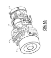
- FIG. 1A is a perspective view of the gas turbine engine with a conventional AGB wrapped around the top of the engine casing;
- FIG. 1B is a disembodied view of a gearing arrangement of a conventional longitudinal AGB
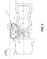
- FIG. 2 is a left side cutaway view of a gas turbine engine with an exemplary transverse AGB installed at the engine casing waist according to embodiments;
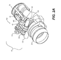
- FIG. 2A is a perspective view of the gas turbine engine with an exemplary transverse AGB installed at the engine casing waist according to embodiments;
- FIG. 2B is a disembodied view of an exemplary view of a gearing arrangement of an exemplary transverse AGB according to embodiments.
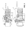
- FIG. 3 is a comparison plan view of the dimensions of the gas turbine engine with the conventional AGB and an exemplary transverse AGB installed.
- FIG. 1 is a simplified cross sectional side view of a gas turbine engine 100 and a conventional AGB 40 mounted thereon at the periphery of the air collector 45.
- a typical gas turbine engine includes an air intake bellmouth 25, a compressor 5, a combustion section 10, an exhaust turbine 15, an exhaust plenum 20 and a conventional AGB 40.
- the compressor 5, the exhaust turbine 15 and the AGB 40 are all coaxially driven by the drive shaft 30, which is shown only in part in the interest of brevity and clarity.
- AGB 40 With the exception of the AGB 40, the entire engine is enclosed in an engine casing 50.
- the engine casing 50 and the AGB 40 must all fit with the confines of an aerodynamic nacelle or within an engine bay.
- a nacelle is a cover housing that is separate from the aircraft fuselage that holds engines, fuel, or equipment.
- accessories 42 that are driven by the accessory gearbox are arranged in a direction that is coaxial with the drive shaft 30 and are dispersed arcuately along an angular segment of the air collector 45 section of the engine casing 50 (See, FIG. 1A ).
- This arrangement permits the accessories 42 to fit between a wall of an engine bay and the engine casing 50.
- the AGB 40 must also be arcuate.
- FIG. 1B is a simplified typical gearing architecture of a conventional AGB 40.
- the AGB 40 may include, inter alia, gearing for a starter 110, an inlet particle accelerator fan 115, a compound idler gear 120, lubrication oil pump 125, an air oil separator 130, a generator shaft 135 and a fuel pump 140.
- the AGB 40 is driven by the drive shaft 30 via a relatively long tower shaft 35 (See FIG. 1 ) and its associated bevel gears.
- the accessories 42 driven by the AGB 40 must be positioned around the circumference of the engine casing 50 to locations on the air collector 45 that are radially the closest to the drive shaft of the gas turbine engine 100 in order to maximize the space available between the nacelle and the engine casing 50.
- the AGB 40 must be simultaneously positioned distantly from the drive shaft 30 to allow the accessories 42 that are mounted on the forward or aft side of the AGB 40 to clear the air collector 45 portion of the engine casing 50.
- the tower shaft 35 must be long enough to extend from the drive shaft 30 to the gearing (See, FIG. 1A ) of the AGB 40.
- the AGB 40 is necessarily laid out in the narrow arcuate configuration that wraps around the engine casing at a distance required to clear the radial profile of the engine casing 50.
- the resulting arcuate arrangement of the AGB 40 makes oil management more difficult because the oil is susceptible to gear churn as it travels along inside the AGB 40 to the various scavenger ports (not shown) towards either distal end of the AGB 40.
- the arcuate arrangement requires more oil scavenging points to collect the lubricating oil and return it to the lubricating oil pump.
- FIG. 2 is a simplified cross sectional side view of the gas turbine engine 100 and an exemplary transverse AGB 40' mounted thereon according to embodiments.
- the gas turbine engine 100 includes the air intake bellmouth 25, the compressor 5, the combustion section 10, the exhaust turbine 15, the exhaust plenum 20 and a transverse AGB 40'.
- the compressor 5, the combustion section 10, the exhaust turbine 15 and the transverse AGB 40' are all driven by the drive shaft 30, which is shown in part in the interest of brevity and clarity.
- a salient feature of the embodiments of FIG. 2 is the rotational axes 41' of the transverse AGB 40' are perpendicular to the drive shaft 30.
- the rotational axes 41' of all of the accessories (not shown) driven by the transverse AGB 40' are also perpendicular to the drive shaft 30.
- the rotational axes 41' of the transverse AGB 40' are disclosed as being perpendicular, it will be appreciated that the rotational axes 41' need not be precisely perpendicular.
- the rotational axes 41' of the transverse AGB 40' may deviate from true perpendicularity as may be required by the overarching design of the gas turbine engine 100.
- the mounting for the transverse AGB 40' may be moved aft from the air collector 45 towards the combustion section 10 to take advantage of the narrower radius of the engine casing in the vicinity of a narrowing (commonly referred to as the waist) 51 of the engine casing 50 that is located in the vicinity of the high pressure stages 7 of the compressor 5.
- the accessories may be aggregated together more compactly in the transverse AGB 40' to fit into the space available at the waist 51.
- the length of the various accessories attached thereto prevented any space savings because the physical size of the accessories clashed either with the air collector 45 or the engine casing 50 in the vicinity of the combustion section 10.
- the tower shaft 35' may be reduced in length thereby eliminating weight and reducing torsion strain that would otherwise occur in a longer tower shaft (such as tower shaft 35 of FIG. 1 ).
- the tower shaft 35' has a first end 202 and a second end 203.
- the fist end 202 is connected to the gearing 42' of the transverse AGB 40' via a translational gear 43 and the second end 203 is connected to the drive shaft 30 via a bevel gear via the opening 36' in the housing 20'.
- oil scavenging is improved.
- By reducing the width and increasing the depth of the transverse AGB 40' most of the AGB lubrication oil returns to the engine casing via the tower shaft opening 36' in the transverse AGB 40'.
- fewer scavenging ports 44 are required in the AGB housing 20' to collect and return the AGB lubrication oil.
- Whatever number of scavenging ports 44 that may be required can be located at the lowest points in the transverse AGB 40'. This may be desirable to scavenge oil when the gas turbine engine 100 is in a non-level flight attitude such that the tower shaft opening 36' is not the lowest point in the transverse AGB 40'.
- FIG 2 illustrates one scavenging port 44 at a potential low point in the transverse AGB 40'.
- Such illustration is merely exemplary and should not be construed as limiting the number of scavenging ports disclosed herein to the single scavenging port 44.
- FIG. 2A is an rendition of an exemplary installation on an HPW3000 gas turbine engine produced by from Advanced Turbine Engine Company (ATEC) with a exemplary transverse mounted AGB 40' according to embodiments.
- the gas turbine engine 100 includes the housing 50, the air intake bellmouth 25, the compressor 5, the combustion section 10, the exhaust turbine 15, the exhaust plenum 20 (See, FIG. 2 ) and the transverse AGB 40'.
- the accessories 42' driven by the transverse AGB may include a starter 110, an inlet particle accelerator fan 115, one or more pumps (120,125), an air oil separator 130, an air turbine starter 135 and a fuel control unit 140.
- FIG. 2B is a disembodied view of an exemplary gearing arrangement for a transverse AGB 40'.
- the transversal AGB 40' is driven by the tower shaft 35' (via a bevel gear) and drives a number of gears (110'-140') for the accessories 42'.
- Exemplary accessories may include the air oil separator 130', fuel pump 120', idler gear 25', starter 110', generator shaft 135' and a lubrication oil pump 140' (See, also FIG 2A ).
- FIG. 3 is a side by side comparison of plan views of an exemplary gas turbine engine with a conventional AGB 40 and with a transverse AGB 40'.
- the width requirement of the transverse AGB 40' is 4.2 in. as compared to the conventional AGB 40 that has a width requirement of 19.2 in., which is a 79% reduction.
- the length requirement in this particular embodiment increases slightly from 10.4 inches to 14.1 inches. Because the AGB 40 represents the widest component of the engine; it is the controlling factor in regard to space constraints within the engine bay or nacelle.
Landscapes
- Engineering & Computer Science (AREA)
- Chemical & Material Sciences (AREA)
- Combustion & Propulsion (AREA)
- Mechanical Engineering (AREA)
- General Engineering & Computer Science (AREA)
- Structures Of Non-Positive Displacement Pumps (AREA)
- Gear Transmission (AREA)
Applications Claiming Priority (1)
| Application Number | Priority Date | Filing Date | Title |
|---|---|---|---|
| US13/160,380 US9145834B2 (en) | 2011-06-14 | 2011-06-14 | Transverse mounted accessory gearbox |
Publications (3)
| Publication Number | Publication Date |
|---|---|
| EP2535544A2 true EP2535544A2 (fr) | 2012-12-19 |
| EP2535544A3 EP2535544A3 (fr) | 2018-03-28 |
| EP2535544B1 EP2535544B1 (fr) | 2020-02-19 |
Family
ID=46022035
Family Applications (1)
| Application Number | Title | Priority Date | Filing Date |
|---|---|---|---|
| EP12163059.4A Active EP2535544B1 (fr) | 2011-06-14 | 2012-04-03 | Boîtier d'entrainement d'accessoires monté en travers |
Country Status (2)
| Country | Link |
|---|---|
| US (1) | US9145834B2 (fr) |
| EP (1) | EP2535544B1 (fr) |
Cited By (11)
| Publication number | Priority date | Publication date | Assignee | Title |
|---|---|---|---|---|
| FR3007463A1 (fr) * | 2013-06-21 | 2014-12-26 | Hispano Suiza Sa | Boitier d'accessoires de turbomachine equipe d'un separateur air/huile |
| FR3017658A1 (fr) * | 2014-02-18 | 2015-08-21 | Hispano Suiza Sa | Boitier d'entrainement d'equipements pour turbomachine |
| EP3054128A1 (fr) | 2015-02-09 | 2016-08-10 | United Technologies Corporation | Transmission pour moteur de turbine à gaz |
| EP3135882A1 (fr) * | 2015-08-26 | 2017-03-01 | Honeywell International Inc. | Boîtier d'accessoires monté transversalement |
| US9752500B2 (en) | 2013-03-14 | 2017-09-05 | Pratt & Whitney Canada Corp. | Gas turbine engine with transmission and method of adjusting rotational speed |
| US9926849B2 (en) | 2011-06-14 | 2018-03-27 | Honeywell International Inc. | Transverse mounted accessory gearbox |
| US10519871B2 (en) | 2017-05-18 | 2019-12-31 | Pratt & Whitney Canada Corp. | Support assembly for a propeller shaft |
| US10738709B2 (en) | 2017-02-09 | 2020-08-11 | Pratt & Whitney Canada Corp. | Multi-spool gas turbine engine |
| US10815899B2 (en) | 2016-11-15 | 2020-10-27 | Pratt & Whitney Canada Corp. | Gas turbine engine accessories arrangement |
| US11174916B2 (en) | 2019-03-21 | 2021-11-16 | Pratt & Whitney Canada Corp. | Aircraft engine reduction gearbox |
| US11268453B1 (en) | 2021-03-17 | 2022-03-08 | Pratt & Whitney Canada Corp. | Lubrication system for aircraft engine reduction gearbox |
Families Citing this family (21)
| Publication number | Priority date | Publication date | Assignee | Title |
|---|---|---|---|---|
| EP3741961B1 (fr) * | 2013-01-30 | 2024-05-01 | RTX Corporation | Boîte de vitesses accessoire de moteur à turbine à gaz |
| GB201311072D0 (en) * | 2013-06-21 | 2013-08-07 | Rolls Royce Deutschland & Co Kg | An accessory mounting for a gas turbine engine |
| US9951695B2 (en) | 2014-04-29 | 2018-04-24 | Honeywell International Inc. | Multi-axis accessory gearboxes of mechanical drive systems and gas turbine engines including the same |
| FR3022301B1 (fr) * | 2014-06-12 | 2016-07-29 | Snecma | Turbomachine comprenant un systeme d'entrainement d'un equipement tel qu'un boitier d'accessoires |
| US10054008B2 (en) * | 2015-02-09 | 2018-08-21 | United Technologies Corporation | Turbomachine accessory gearbox bracket |
| US9605562B2 (en) | 2015-02-09 | 2017-03-28 | United Techologies Corporation | Turbomachine accessory gearbox alignment pin |
| US9835239B2 (en) | 2016-01-21 | 2017-12-05 | General Electric Company | Composite gearbox housing |
| US10662878B2 (en) | 2016-02-03 | 2020-05-26 | Honeywell Internatioanl Inc. | Compact accessory systems for a gas turbine engine |
| US10883424B2 (en) | 2016-07-19 | 2021-01-05 | Pratt & Whitney Canada Corp. | Multi-spool gas turbine engine architecture |
| US11415063B2 (en) | 2016-09-15 | 2022-08-16 | Pratt & Whitney Canada Corp. | Reverse-flow gas turbine engine |
| US10465611B2 (en) | 2016-09-15 | 2019-11-05 | Pratt & Whitney Canada Corp. | Reverse flow multi-spool gas turbine engine with aft-end accessory gearbox drivingly connected to both high pressure spool and low pressure spool |
| US11035293B2 (en) | 2016-09-15 | 2021-06-15 | Pratt & Whitney Canada Corp. | Reverse flow gas turbine engine with offset RGB |
| FR3061141B1 (fr) * | 2016-12-22 | 2019-01-25 | Airbus Helicopters | Carter de boite de transmission de puissance, boite de puissance et aeronef |
| US10808624B2 (en) | 2017-02-09 | 2020-10-20 | Pratt & Whitney Canada Corp. | Turbine rotor with low over-speed requirements |
| US11174782B2 (en) | 2017-02-10 | 2021-11-16 | Pratt & Whitney Canada Corp. | Planetary gearbox for gas turbine engine |
| US10746188B2 (en) | 2017-03-14 | 2020-08-18 | Pratt & Whitney Canada Corp. | Inter-shaft bearing connected to a compressor boost system |
| US10823080B2 (en) | 2017-05-31 | 2020-11-03 | General Electric Company | Dual accessory gearbox |
| GB201716499D0 (en) * | 2017-10-09 | 2017-11-22 | Rolls Royce Plc | Gas turbine engine fireproofing |
| EP4339440A3 (fr) | 2018-08-08 | 2024-05-22 | Pratt & Whitney Canada Corp. | Système et procédé multimoteur |
| US11572838B2 (en) * | 2020-09-29 | 2023-02-07 | General Electric Company | Accessory gearbox for a turbine engine |
| US12372030B2 (en) | 2023-12-15 | 2025-07-29 | General Electric Company | Turbine engine having a fire box |
Family Cites Families (18)
| Publication number | Priority date | Publication date | Assignee | Title |
|---|---|---|---|---|
| US2638744A (en) * | 1948-12-09 | 1953-05-19 | Lockheed Aircraft Corp | Turbine power plant having auxiliary units |
| US2608056A (en) * | 1950-11-07 | 1952-08-26 | A V Roe Canada Ltd | Power take-off from the forward end of aircraft propulsive power units |
| US3455182A (en) | 1967-04-12 | 1969-07-15 | Garrett Corp | Helicopter lift augmentation means |
| US3714779A (en) * | 1970-09-28 | 1973-02-06 | Avco Corp | Gas turbine engine having a horizontal accessory gear box |
| US4068470A (en) | 1974-11-08 | 1978-01-17 | The United States Of America As Represented By The Administrator Of The National Aeronautics And Space Administration | Gas turbine engine with convertible accessories |
| US5143329A (en) | 1990-06-01 | 1992-09-01 | General Electric Company | Gas turbine engine powered aircraft environmental control system and boundary layer bleed |
| US5687561A (en) | 1991-09-17 | 1997-11-18 | Rolls-Royce Plc | Ducted fan gas turbine engine accessory drive |
| GB0315894D0 (en) | 2003-07-08 | 2003-08-13 | Rolls Royce Plc | Aircraft engine arrangement |
| US6883750B2 (en) | 2003-07-16 | 2005-04-26 | Sikorsky Aircraft Corporation | Split torque gearbox with pivoted engine support |
| US7063734B2 (en) * | 2004-03-23 | 2006-06-20 | Pratt & Whitney Canada Corp. | Air/oil separation system and method |
| US7500365B2 (en) | 2005-05-05 | 2009-03-10 | United Technologies Corporation | Accessory gearbox |
| US20080073152A1 (en) * | 2006-09-25 | 2008-03-27 | Pratt & Whitney Canada Corp. | Tower shaft (uts) shielding |
| US20090212156A1 (en) | 2007-09-06 | 2009-08-27 | Honeywell International, Inc. | Aircraft engine system with gearbox unit |
| US8333554B2 (en) | 2007-11-14 | 2012-12-18 | United Technologies Corporation | Split gearbox and nacelle arrangement |
| US9719428B2 (en) | 2007-11-30 | 2017-08-01 | United Technologies Corporation | Gas turbine engine with pylon mounted accessory drive |
| US20090223052A1 (en) | 2008-03-04 | 2009-09-10 | Chaudhry Zaffir A | Gearbox gear and nacelle arrangement |
| US9816441B2 (en) | 2009-03-30 | 2017-11-14 | United Technologies Corporation | Gas turbine engine with stacked accessory components |
| US8490410B2 (en) * | 2010-11-17 | 2013-07-23 | United Technologies Corporation | Axial accessory gearbox |
-
2011
- 2011-06-14 US US13/160,380 patent/US9145834B2/en not_active Expired - Fee Related
-
2012
- 2012-04-03 EP EP12163059.4A patent/EP2535544B1/fr active Active
Non-Patent Citations (1)
| Title |
|---|
| None |
Cited By (15)
| Publication number | Priority date | Publication date | Assignee | Title |
|---|---|---|---|---|
| US9926849B2 (en) | 2011-06-14 | 2018-03-27 | Honeywell International Inc. | Transverse mounted accessory gearbox |
| US9752500B2 (en) | 2013-03-14 | 2017-09-05 | Pratt & Whitney Canada Corp. | Gas turbine engine with transmission and method of adjusting rotational speed |
| FR3007463A1 (fr) * | 2013-06-21 | 2014-12-26 | Hispano Suiza Sa | Boitier d'accessoires de turbomachine equipe d'un separateur air/huile |
| FR3017658A1 (fr) * | 2014-02-18 | 2015-08-21 | Hispano Suiza Sa | Boitier d'entrainement d'equipements pour turbomachine |
| WO2015124857A1 (fr) * | 2014-02-18 | 2015-08-27 | Hispano Suiza | Boîtier d'entrainement d'équipements pour turbomachine |
| US10190505B2 (en) | 2014-02-18 | 2019-01-29 | Safran Transmission Systems | Housing for driving an apparatus for a turbine engine |
| EP3054128A1 (fr) | 2015-02-09 | 2016-08-10 | United Technologies Corporation | Transmission pour moteur de turbine à gaz |
| EP3628850A1 (fr) * | 2015-02-09 | 2020-04-01 | United Technologies Corporation | Transmission pour moteur de turbine à gaz |
| EP3135882A1 (fr) * | 2015-08-26 | 2017-03-01 | Honeywell International Inc. | Boîtier d'accessoires monté transversalement |
| US10815899B2 (en) | 2016-11-15 | 2020-10-27 | Pratt & Whitney Canada Corp. | Gas turbine engine accessories arrangement |
| US10738709B2 (en) | 2017-02-09 | 2020-08-11 | Pratt & Whitney Canada Corp. | Multi-spool gas turbine engine |
| US10519871B2 (en) | 2017-05-18 | 2019-12-31 | Pratt & Whitney Canada Corp. | Support assembly for a propeller shaft |
| US11174916B2 (en) | 2019-03-21 | 2021-11-16 | Pratt & Whitney Canada Corp. | Aircraft engine reduction gearbox |
| US11268453B1 (en) | 2021-03-17 | 2022-03-08 | Pratt & Whitney Canada Corp. | Lubrication system for aircraft engine reduction gearbox |
| US12392293B2 (en) | 2021-03-17 | 2025-08-19 | Pratt & Whitney Canada Corp. | Lubrication system for aircraft engine reduction gearbox |
Also Published As
| Publication number | Publication date |
|---|---|
| US20120317991A1 (en) | 2012-12-20 |
| US9145834B2 (en) | 2015-09-29 |
| EP2535544B1 (fr) | 2020-02-19 |
| EP2535544A3 (fr) | 2018-03-28 |
Similar Documents
| Publication | Publication Date | Title |
|---|---|---|
| US9145834B2 (en) | Transverse mounted accessory gearbox | |
| US9926849B2 (en) | Transverse mounted accessory gearbox | |
| EP3135882B1 (fr) | Boîtier d'accessoires monté transversalement | |
| EP2085589B2 (fr) | Ensemble accessoires, boîte de vitesse et moteur à turbine à gaz correspondants | |
| US9121351B2 (en) | Gas turbine engine accessory system | |
| US7351174B2 (en) | Twin turbo-shaft engine with accessory gearbox drive means | |
| RU2005141169A (ru) | Устройство турбинного двигателя с | |
| US8328504B2 (en) | Aeroengine drain assembly | |
| EP2372129A2 (fr) | Arrangement de montage pour les accessoires de turbines à gaz | |
| CN1840878A (zh) | 双轴涡轮发动机、其动力输出模块和装配该发动机的方法 | |
| US11639228B2 (en) | Engine layouts and associated compartmentalization for aircraft having hybrid-electric propulsion system | |
| EP2065585A2 (fr) | Moteur à turbine à gaz doté d'un entraînement accessoire monté sur pylône | |
| US12116939B2 (en) | Hybrid transmission on propeller gearbox | |
| US10364752B2 (en) | System and method for an integral drive engine with a forward main gearbox | |
| US9951695B2 (en) | Multi-axis accessory gearboxes of mechanical drive systems and gas turbine engines including the same | |
| CN116209821B (zh) | 设置有螺旋桨和偏置定子轮叶的涡轮机模块 | |
| JP2005513346A (ja) | オフセットされた駆動部を備えたガスタービンエンジン | |
| EP3699414B1 (fr) | Moteur à turbine à gaz avec boîte de vitesses accessoire | |
| US20260015976A1 (en) | Turbine engine including transfer gearbox and accessory gearbox | |
| RU2522208C1 (ru) | Пилон газотурбинного двигателя в сборе и система газотурбинного двигателя | |
| EP4390063A1 (fr) | Conduit d'échappement pour centrale électrique d'aéronef hybride | |
| US20250290452A1 (en) | Turbine engine with accessory gearbox | |
| US12203411B2 (en) | Engine controller for a gas turbine engine | |
| EP4484731A1 (fr) | Dispositif de commande de moteur pour moteur à turbine à gaz | |
| US20250075662A1 (en) | Turbine Engine having First and Second Accessory Gearboxes |
Legal Events
| Date | Code | Title | Description |
|---|---|---|---|
| PUAI | Public reference made under article 153(3) epc to a published international application that has entered the european phase |
Free format text: ORIGINAL CODE: 0009012 |
|
| 17P | Request for examination filed |
Effective date: 20120403 |
|
| AK | Designated contracting states |
Kind code of ref document: A2 Designated state(s): AL AT BE BG CH CY CZ DE DK EE ES FI FR GB GR HR HU IE IS IT LI LT LU LV MC MK MT NL NO PL PT RO RS SE SI SK SM TR |
|
| AX | Request for extension of the european patent |
Extension state: BA ME |
|
| RAP1 | Party data changed (applicant data changed or rights of an application transferred) |
Owner name: HONEYWELL INTERNATIONAL INC. |
|
| PUAL | Search report despatched |
Free format text: ORIGINAL CODE: 0009013 |
|
| STAA | Information on the status of an ep patent application or granted ep patent |
Free format text: STATUS: EXAMINATION IS IN PROGRESS |
|
| AK | Designated contracting states |
Kind code of ref document: A3 Designated state(s): AL AT BE BG CH CY CZ DE DK EE ES FI FR GB GR HR HU IE IS IT LI LT LU LV MC MK MT NL NO PL PT RO RS SE SI SK SM TR |
|
| AX | Request for extension of the european patent |
Extension state: BA ME |
|
| RIC1 | Information provided on ipc code assigned before grant |
Ipc: F02C 7/32 20060101AFI20180222BHEP |
|
| 17Q | First examination report despatched |
Effective date: 20180323 |
|
| GRAP | Despatch of communication of intention to grant a patent |
Free format text: ORIGINAL CODE: EPIDOSNIGR1 |
|
| STAA | Information on the status of an ep patent application or granted ep patent |
Free format text: STATUS: GRANT OF PATENT IS INTENDED |
|
| INTG | Intention to grant announced |
Effective date: 20190903 |
|
| GRAS | Grant fee paid |
Free format text: ORIGINAL CODE: EPIDOSNIGR3 |
|
| GRAJ | Information related to disapproval of communication of intention to grant by the applicant or resumption of examination proceedings by the epo deleted |
Free format text: ORIGINAL CODE: EPIDOSDIGR1 |
|
| GRAL | Information related to payment of fee for publishing/printing deleted |
Free format text: ORIGINAL CODE: EPIDOSDIGR3 |
|
| STAA | Information on the status of an ep patent application or granted ep patent |
Free format text: STATUS: EXAMINATION IS IN PROGRESS |
|
| GRAP | Despatch of communication of intention to grant a patent |
Free format text: ORIGINAL CODE: EPIDOSNIGR1 |
|
| STAA | Information on the status of an ep patent application or granted ep patent |
Free format text: STATUS: GRANT OF PATENT IS INTENDED |
|
| INTC | Intention to grant announced (deleted) | ||
| GRAA | (expected) grant |
Free format text: ORIGINAL CODE: 0009210 |
|
| STAA | Information on the status of an ep patent application or granted ep patent |
Free format text: STATUS: THE PATENT HAS BEEN GRANTED |
|
| INTG | Intention to grant announced |
Effective date: 20200107 |
|
| AK | Designated contracting states |
Kind code of ref document: B1 Designated state(s): AL AT BE BG CH CY CZ DE DK EE ES FI FR GB GR HR HU IE IS IT LI LT LU LV MC MK MT NL NO PL PT RO RS SE SI SK SM TR |
|
| REG | Reference to a national code |
Ref country code: GB Ref legal event code: FG4D |
|
| REG | Reference to a national code |
Ref country code: CH Ref legal event code: EP |
|
| REG | Reference to a national code |
Ref country code: DE Ref legal event code: R096 Ref document number: 602012067835 Country of ref document: DE |
|
| REG | Reference to a national code |
Ref country code: AT Ref legal event code: REF Ref document number: 1235233 Country of ref document: AT Kind code of ref document: T Effective date: 20200315 |
|
| REG | Reference to a national code |
Ref country code: IE Ref legal event code: FG4D |
|
| REG | Reference to a national code |
Ref country code: NL Ref legal event code: MP Effective date: 20200219 |
|
| PG25 | Lapsed in a contracting state [announced via postgrant information from national office to epo] |
Ref country code: RS Free format text: LAPSE BECAUSE OF FAILURE TO SUBMIT A TRANSLATION OF THE DESCRIPTION OR TO PAY THE FEE WITHIN THE PRESCRIBED TIME-LIMIT Effective date: 20200219 Ref country code: NO Free format text: LAPSE BECAUSE OF FAILURE TO SUBMIT A TRANSLATION OF THE DESCRIPTION OR TO PAY THE FEE WITHIN THE PRESCRIBED TIME-LIMIT Effective date: 20200519 Ref country code: FI Free format text: LAPSE BECAUSE OF FAILURE TO SUBMIT A TRANSLATION OF THE DESCRIPTION OR TO PAY THE FEE WITHIN THE PRESCRIBED TIME-LIMIT Effective date: 20200219 |
|
| REG | Reference to a national code |
Ref country code: LT Ref legal event code: MG4D |
|
| PG25 | Lapsed in a contracting state [announced via postgrant information from national office to epo] |
Ref country code: HR Free format text: LAPSE BECAUSE OF FAILURE TO SUBMIT A TRANSLATION OF THE DESCRIPTION OR TO PAY THE FEE WITHIN THE PRESCRIBED TIME-LIMIT Effective date: 20200219 Ref country code: SE Free format text: LAPSE BECAUSE OF FAILURE TO SUBMIT A TRANSLATION OF THE DESCRIPTION OR TO PAY THE FEE WITHIN THE PRESCRIBED TIME-LIMIT Effective date: 20200219 Ref country code: LV Free format text: LAPSE BECAUSE OF FAILURE TO SUBMIT A TRANSLATION OF THE DESCRIPTION OR TO PAY THE FEE WITHIN THE PRESCRIBED TIME-LIMIT Effective date: 20200219 Ref country code: BG Free format text: LAPSE BECAUSE OF FAILURE TO SUBMIT A TRANSLATION OF THE DESCRIPTION OR TO PAY THE FEE WITHIN THE PRESCRIBED TIME-LIMIT Effective date: 20200519 Ref country code: GR Free format text: LAPSE BECAUSE OF FAILURE TO SUBMIT A TRANSLATION OF THE DESCRIPTION OR TO PAY THE FEE WITHIN THE PRESCRIBED TIME-LIMIT Effective date: 20200520 Ref country code: IS Free format text: LAPSE BECAUSE OF FAILURE TO SUBMIT A TRANSLATION OF THE DESCRIPTION OR TO PAY THE FEE WITHIN THE PRESCRIBED TIME-LIMIT Effective date: 20200619 |
|
| PG25 | Lapsed in a contracting state [announced via postgrant information from national office to epo] |
Ref country code: NL Free format text: LAPSE BECAUSE OF FAILURE TO SUBMIT A TRANSLATION OF THE DESCRIPTION OR TO PAY THE FEE WITHIN THE PRESCRIBED TIME-LIMIT Effective date: 20200219 |
|
| PG25 | Lapsed in a contracting state [announced via postgrant information from national office to epo] |
Ref country code: CZ Free format text: LAPSE BECAUSE OF FAILURE TO SUBMIT A TRANSLATION OF THE DESCRIPTION OR TO PAY THE FEE WITHIN THE PRESCRIBED TIME-LIMIT Effective date: 20200219 Ref country code: RO Free format text: LAPSE BECAUSE OF FAILURE TO SUBMIT A TRANSLATION OF THE DESCRIPTION OR TO PAY THE FEE WITHIN THE PRESCRIBED TIME-LIMIT Effective date: 20200219 Ref country code: SK Free format text: LAPSE BECAUSE OF FAILURE TO SUBMIT A TRANSLATION OF THE DESCRIPTION OR TO PAY THE FEE WITHIN THE PRESCRIBED TIME-LIMIT Effective date: 20200219 Ref country code: PT Free format text: LAPSE BECAUSE OF FAILURE TO SUBMIT A TRANSLATION OF THE DESCRIPTION OR TO PAY THE FEE WITHIN THE PRESCRIBED TIME-LIMIT Effective date: 20200712 Ref country code: DK Free format text: LAPSE BECAUSE OF FAILURE TO SUBMIT A TRANSLATION OF THE DESCRIPTION OR TO PAY THE FEE WITHIN THE PRESCRIBED TIME-LIMIT Effective date: 20200219 Ref country code: EE Free format text: LAPSE BECAUSE OF FAILURE TO SUBMIT A TRANSLATION OF THE DESCRIPTION OR TO PAY THE FEE WITHIN THE PRESCRIBED TIME-LIMIT Effective date: 20200219 Ref country code: SM Free format text: LAPSE BECAUSE OF FAILURE TO SUBMIT A TRANSLATION OF THE DESCRIPTION OR TO PAY THE FEE WITHIN THE PRESCRIBED TIME-LIMIT Effective date: 20200219 Ref country code: LT Free format text: LAPSE BECAUSE OF FAILURE TO SUBMIT A TRANSLATION OF THE DESCRIPTION OR TO PAY THE FEE WITHIN THE PRESCRIBED TIME-LIMIT Effective date: 20200219 Ref country code: ES Free format text: LAPSE BECAUSE OF FAILURE TO SUBMIT A TRANSLATION OF THE DESCRIPTION OR TO PAY THE FEE WITHIN THE PRESCRIBED TIME-LIMIT Effective date: 20200219 |
|
| REG | Reference to a national code |
Ref country code: AT Ref legal event code: MK05 Ref document number: 1235233 Country of ref document: AT Kind code of ref document: T Effective date: 20200219 |
|
| REG | Reference to a national code |
Ref country code: DE Ref legal event code: R097 Ref document number: 602012067835 Country of ref document: DE |
|
| PG25 | Lapsed in a contracting state [announced via postgrant information from national office to epo] |
Ref country code: MC Free format text: LAPSE BECAUSE OF FAILURE TO SUBMIT A TRANSLATION OF THE DESCRIPTION OR TO PAY THE FEE WITHIN THE PRESCRIBED TIME-LIMIT Effective date: 20200219 |
|
| REG | Reference to a national code |
Ref country code: CH Ref legal event code: PL |
|
| PLBE | No opposition filed within time limit |
Free format text: ORIGINAL CODE: 0009261 |
|
| STAA | Information on the status of an ep patent application or granted ep patent |
Free format text: STATUS: NO OPPOSITION FILED WITHIN TIME LIMIT |
|
| 26N | No opposition filed |
Effective date: 20201120 |
|
| PG25 | Lapsed in a contracting state [announced via postgrant information from national office to epo] |
Ref country code: AT Free format text: LAPSE BECAUSE OF FAILURE TO SUBMIT A TRANSLATION OF THE DESCRIPTION OR TO PAY THE FEE WITHIN THE PRESCRIBED TIME-LIMIT Effective date: 20200219 Ref country code: FR Free format text: LAPSE BECAUSE OF NON-PAYMENT OF DUE FEES Effective date: 20200419 Ref country code: LI Free format text: LAPSE BECAUSE OF NON-PAYMENT OF DUE FEES Effective date: 20200430 Ref country code: IT Free format text: LAPSE BECAUSE OF FAILURE TO SUBMIT A TRANSLATION OF THE DESCRIPTION OR TO PAY THE FEE WITHIN THE PRESCRIBED TIME-LIMIT Effective date: 20200219 Ref country code: LU Free format text: LAPSE BECAUSE OF NON-PAYMENT OF DUE FEES Effective date: 20200403 Ref country code: CH Free format text: LAPSE BECAUSE OF NON-PAYMENT OF DUE FEES Effective date: 20200430 |
|
| REG | Reference to a national code |
Ref country code: BE Ref legal event code: MM Effective date: 20200430 |
|
| PG25 | Lapsed in a contracting state [announced via postgrant information from national office to epo] |
Ref country code: PL Free format text: LAPSE BECAUSE OF FAILURE TO SUBMIT A TRANSLATION OF THE DESCRIPTION OR TO PAY THE FEE WITHIN THE PRESCRIBED TIME-LIMIT Effective date: 20200219 Ref country code: BE Free format text: LAPSE BECAUSE OF NON-PAYMENT OF DUE FEES Effective date: 20200430 Ref country code: SI Free format text: LAPSE BECAUSE OF FAILURE TO SUBMIT A TRANSLATION OF THE DESCRIPTION OR TO PAY THE FEE WITHIN THE PRESCRIBED TIME-LIMIT Effective date: 20200219 |
|
| GBPC | Gb: european patent ceased through non-payment of renewal fee |
Effective date: 20200519 |
|
| PG25 | Lapsed in a contracting state [announced via postgrant information from national office to epo] |
Ref country code: GB Free format text: LAPSE BECAUSE OF NON-PAYMENT OF DUE FEES Effective date: 20200519 Ref country code: IE Free format text: LAPSE BECAUSE OF NON-PAYMENT OF DUE FEES Effective date: 20200403 |
|
| PG25 | Lapsed in a contracting state [announced via postgrant information from national office to epo] |
Ref country code: TR Free format text: LAPSE BECAUSE OF FAILURE TO SUBMIT A TRANSLATION OF THE DESCRIPTION OR TO PAY THE FEE WITHIN THE PRESCRIBED TIME-LIMIT Effective date: 20200219 Ref country code: MT Free format text: LAPSE BECAUSE OF FAILURE TO SUBMIT A TRANSLATION OF THE DESCRIPTION OR TO PAY THE FEE WITHIN THE PRESCRIBED TIME-LIMIT Effective date: 20200219 Ref country code: CY Free format text: LAPSE BECAUSE OF FAILURE TO SUBMIT A TRANSLATION OF THE DESCRIPTION OR TO PAY THE FEE WITHIN THE PRESCRIBED TIME-LIMIT Effective date: 20200219 |
|
| PG25 | Lapsed in a contracting state [announced via postgrant information from national office to epo] |
Ref country code: MK Free format text: LAPSE BECAUSE OF FAILURE TO SUBMIT A TRANSLATION OF THE DESCRIPTION OR TO PAY THE FEE WITHIN THE PRESCRIBED TIME-LIMIT Effective date: 20200219 Ref country code: AL Free format text: LAPSE BECAUSE OF FAILURE TO SUBMIT A TRANSLATION OF THE DESCRIPTION OR TO PAY THE FEE WITHIN THE PRESCRIBED TIME-LIMIT Effective date: 20200219 |
|
| PGFP | Annual fee paid to national office [announced via postgrant information from national office to epo] |
Ref country code: DE Payment date: 20220428 Year of fee payment: 11 |
|
| P01 | Opt-out of the competence of the unified patent court (upc) registered |
Effective date: 20230525 |
|
| REG | Reference to a national code |
Ref country code: DE Ref legal event code: R119 Ref document number: 602012067835 Country of ref document: DE |
|
| PG25 | Lapsed in a contracting state [announced via postgrant information from national office to epo] |
Ref country code: DE Free format text: LAPSE BECAUSE OF NON-PAYMENT OF DUE FEES Effective date: 20231103 |