EP2541199B1 - Raumschiff, das mit einer Vorrichtung zum Schätzen seines Geschwindigkeitsvektors in Bezug auf ein Inertialsystem ausgestattet ist, und entsprechendes Schätzverfahren - Google Patents
Raumschiff, das mit einer Vorrichtung zum Schätzen seines Geschwindigkeitsvektors in Bezug auf ein Inertialsystem ausgestattet ist, und entsprechendes Schätzverfahren Download PDFInfo
- Publication number
- EP2541199B1 EP2541199B1 EP12173874.4A EP12173874A EP2541199B1 EP 2541199 B1 EP2541199 B1 EP 2541199B1 EP 12173874 A EP12173874 A EP 12173874A EP 2541199 B1 EP2541199 B1 EP 2541199B1
- Authority
- EP
- European Patent Office
- Prior art keywords
- spacecraft
- reference frame
- vector
- relative
- magnetic field
- Prior art date
- Legal status (The legal status is an assumption and is not a legal conclusion. Google has not performed a legal analysis and makes no representation as to the accuracy of the status listed.)
- Active
Links
Images


Classifications
-
- G—PHYSICS
- G01—MEASURING; TESTING
- G01C—MEASURING DISTANCES, LEVELS OR BEARINGS; SURVEYING; NAVIGATION; GYROSCOPIC INSTRUMENTS; PHOTOGRAMMETRY OR VIDEOGRAMMETRY
- G01C21/00—Navigation; Navigational instruments not provided for in groups G01C1/00 - G01C19/00
- G01C21/10—Navigation; Navigational instruments not provided for in groups G01C1/00 - G01C19/00 by using measurements of speed or acceleration
- G01C21/12—Navigation; Navigational instruments not provided for in groups G01C1/00 - G01C19/00 by using measurements of speed or acceleration executed aboard the object being navigated; Dead reckoning
- G01C21/16—Navigation; Navigational instruments not provided for in groups G01C1/00 - G01C19/00 by using measurements of speed or acceleration executed aboard the object being navigated; Dead reckoning by integrating acceleration or speed, i.e. inertial navigation
- G01C21/165—Navigation; Navigational instruments not provided for in groups G01C1/00 - G01C19/00 by using measurements of speed or acceleration executed aboard the object being navigated; Dead reckoning by integrating acceleration or speed, i.e. inertial navigation combined with non-inertial navigation instruments
- G01C21/1654—Navigation; Navigational instruments not provided for in groups G01C1/00 - G01C19/00 by using measurements of speed or acceleration executed aboard the object being navigated; Dead reckoning by integrating acceleration or speed, i.e. inertial navigation combined with non-inertial navigation instruments with electromagnetic compass
-
- B—PERFORMING OPERATIONS; TRANSPORTING
- B64—AIRCRAFT; AVIATION; COSMONAUTICS
- B64G—COSMONAUTICS; VEHICLES OR EQUIPMENT THEREFOR
- B64G1/00—Cosmonautic vehicles
- B64G1/22—Parts of, or equipment specially adapted for fitting in or to, cosmonautic vehicles
- B64G1/24—Guiding or controlling apparatus, e.g. for attitude control
- B64G1/36—Guiding or controlling apparatus, e.g. for attitude control using sensors, e.g. sun-sensors, horizon sensors
- B64G1/366—Guiding or controlling apparatus, e.g. for attitude control using sensors, e.g. sun-sensors, horizon sensors using magnetometers
-
- B—PERFORMING OPERATIONS; TRANSPORTING
- B64—AIRCRAFT; AVIATION; COSMONAUTICS
- B64G—COSMONAUTICS; VEHICLES OR EQUIPMENT THEREFOR
- B64G1/00—Cosmonautic vehicles
- B64G1/22—Parts of, or equipment specially adapted for fitting in or to, cosmonautic vehicles
- B64G1/24—Guiding or controlling apparatus, e.g. for attitude control
- B64G1/36—Guiding or controlling apparatus, e.g. for attitude control using sensors, e.g. sun-sensors, horizon sensors
- B64G1/369—Guiding or controlling apparatus, e.g. for attitude control using sensors, e.g. sun-sensors, horizon sensors using gyroscopes as attitude sensors
-
- G—PHYSICS
- G01—MEASURING; TESTING
- G01C—MEASURING DISTANCES, LEVELS OR BEARINGS; SURVEYING; NAVIGATION; GYROSCOPIC INSTRUMENTS; PHOTOGRAMMETRY OR VIDEOGRAMMETRY
- G01C21/00—Navigation; Navigational instruments not provided for in groups G01C1/00 - G01C19/00
- G01C21/04—Navigation; Navigational instruments not provided for in groups G01C1/00 - G01C19/00 by terrestrial means
- G01C21/08—Navigation; Navigational instruments not provided for in groups G01C1/00 - G01C19/00 by terrestrial means involving use of the magnetic field of the earth
Definitions
- the present invention relates to a spacecraft equipped with a device for estimating a speed vector of the spacecraft with respect to an inertial reference system, the estimation device comprising at least one onboard gyrometer aboard the spacecraft. and capable of measuring a vector of instantaneous speed of rotation of the spacecraft relative to the inertial reference frame.
- the speed relative to an inertial reference is obtained by integration with respect to the acceleration time of the vehicle, the acceleration being estimated from measurements made by accelerometers and gyrometers embedded on the spacecraft.
- Such a method of determination does not, however, give complete satisfaction. Indeed, because of the integration, the value of the speed obtained is tainted with an error that increases linearly with time.
- the speed determined by this method therefore has the disadvantage of having a precision which decreases with time. It is therefore all the less precise that the flight time of the craft is long.
- EP 2 048 475 describes a device for determining the speed of a machine, by applying a correction factor to a predicted speed from a mechanical model.
- the correction factor is calculated by comparing the magnetic field known in the inertial reference frame and the magnetic field measured by the machine.
- FR 2 914 739 describes a method of estimating the kinematics of a body traveling on the earth using the variations of the magnetic field.
- An object of the invention is to provide a device and an associated method of estimating the speed of a spacecraft that allows to obtain at any time a precise value of the speed regardless of the time of flight of the vehicle.
- the invention relates to a spacecraft of the aforementioned type, according to claim 1.
- the spacecraft is characterized in that the estimation device further comprises a magnetometers network linked to the spacecraft and spatially spaced, suitable for measuring, in a frame of reference related to the spacecraft, a magnetic field vector produced by a star, the magnetic field vector produced by the star being stationary in a frame linked to the star and a computer, configured to estimate the speed vector of the spacecraft by solving an equation connecting the speed vector of the spacecraft relative to the inertial reference vector to the vector instantaneous speed of rotation of the spacecraft relative to the inertial reference vector, to the vector magnetic field produced by the star, at the time derivative and at the spatial gradient of the magnetic field vector produced by the star, at a vector position of the vehicle spatial with respect to the center of the inertial reference frame and a rotation speed vector of the reference linked to the star with respect to the inertial reference frame.
- the figure 1 schematically illustrates a set of reference frames used for determining the speed of the spacecraft.
- These repositories include a repository linked to the Earth RT, a geocentric inertial reference system RI and a mobile reference frame RL linked to the spacecraft.
- the reference linked to the Earth RT revolves around an axis of rotation of the Earth on itself (axis of the poles) at an angular speed equal to the speed of rotation of the Earth on itself. even around the pole axis ⁇ RT / RI .
- the rotational speed ⁇ RT / RI is approximately equal to 7.29 x 10 -5 rad / s, that is to say that the Earth makes a turn on itself in about 23 hours 56 minutes and 4 seconds.
- repositories RL, RI and RT are defined more precisely as follows.
- the RT reference is fixed relative to the Earth. He turns with the Earth. It is for example a geocentric equatorial reference rotating with the Earth.
- this reference system comprises an origin which is the center of mass C of the Earth, an axis A RT contained in the plane of the equator E and passing through the point of intersection of the equator E with a meridian M reference, for example the meridian corresponding to the longitude of Kourou, a C RT axis coinciding with the mean earth rotation axis and a B RT axis directly supplementing the RT reference.
- the inertial reference frame RI is for example an equatorial geocentric inertial reference.
- the equatorial geocentric inertial reference comprises an origin which is the center of mass C of the Earth, an axis A RI pointing to a fixed distant star, an axis C RI coinciding with the mean axis of rotation of the Earth and with the axis C RT rotating geocentric equatorial reference RT and an axis B RI pointing to a distant star fixed and directly complementing the reference RI.
- the axes A RI and B RI retain fixed inertial directions.
- the inertial reference frame RI coincides with the reference linked to the Earth RT.
- the origin of the inertial reference frame RI coincides with the origin of the reference frame RT linked to the Earth.
- the RL repository is an arbitrary repository related to the structure of the spacecraft. It is fixed with respect to the spacecraft and moves with the spacecraft. It comprises for example an origin O at the center of mass of the spacecraft 1. Its axes A RL , B RL and C RL form a trihedron, the axis A RL being for example merged with a main axis of the machine, for example with a direction of elongation of the machine.
- the Earth is designated by the reference "T".
- the Earth's magnetic field B that is to say, the magnetic field produced by the Earth, turns with the Earth. So we assume that the Earth's magnetic field vector B is stationary in the reference linked to the Earth RT, that is to say that, in this reference frame RT, it is independent of time and depends only on the position with respect to the origin of the inertial reference frame RI (which coincides with that of the RT repository). In other words, in the RT repository, the magnetic field vector B does not vary with time, which is expressed mathematically as follows: ⁇ B ⁇ ⁇ t
- RT , X 0 ⁇ .
- ⁇ ⁇ t denotes the partial derivative with respect to time and
- the figure 2 schematically illustrates a spacecraft 1 equipped with a device 5 for estimating the speed of the spacecraft 1 according to the invention.
- the spacecraft 1 is a space launcher, in particular a rocket.
- it is an interplanetary probe, a satellite or a transport module, for example a transport module for the international space station.
- the inertial unit 7 comprises an accelerometer 11 able to measure a specific acceleration vector at RL of the spacecraft 1 compared to the reference frame related to the spacecraft RL.
- the specific acceleration vector at RL corresponds to the acceleration of the spacecraft 1 minus the acceleration due to gravity.
- the accelerometer 11 is able to measure the specific acceleration at RL of the spacecraft 1 along three measurement axes forming a measurement trihedron, in particular along the three axes A RL , B RL , C RL of the reference frame RL.
- the accelerometer 11 is for example a triaxial accelerometer or a set of three uniaxial accelerometers whose axes jointly form the measurement trihedron.
- the estimating device 5 further comprises an array 13 of magnetometers 15 fixed to the spacecraft 1 in a spatially spaced manner.
- the network 13 of magnetometers 15 is suitable for measuring the vector terrestrial magnetic field B RL in the RL repository linked to the spacecraft. It is particularly suitable for measuring the components of the terrestrial magnetic field vector B RL following each of the axes A RL , B RL , C RL of the reference frame RL linked to the spacecraft.
- the network 13 of magnetometers 15 is further clean, particularly because of its geometry, to allow the determination, at each measurement moment of the magnetometers 15, of a spatial gradient ⁇ B ⁇ X RL of the Earth's magnetic field vector B RL , and in particular coefficients of this gradient ⁇ B ⁇ X RL according to each of the axes A RL , B RL , C RL of the reference frame RL linked to the spacecraft.
- Each coefficient of the gradient ⁇ B ⁇ X RL is for example determined by a method using vector measurements of the Earth's magnetic field B realized by the magnetometers 15 of the network 13, associated with optimization methods of the least square type or median filter or associated with the intrinsic properties of the magnetic field described by the Maxwell equations.
- any other conventional method adapted to calculate the coefficients of the gradient ⁇ B ⁇ X RL appropriate.
- the network 13 comprises at least four non-coplanar magnetometers.
- the network 13 is formed by four magnetometers 15 arranged at the vertices of a tetrahedron.
- any other geometric arrangement magnetometers 15 of the network 13 able to allow both the measurement of the components of the magnetic field vector B RL and the determination of the coefficients of the spatial gradient ⁇ B ⁇ X RL following each axis of the RL repository is appropriate.
- the magnetometers 15 are arranged at the vertices of a parallelepiped, for example of a cube or at the vertices of a regular polyhedron or not provided that it is not plane.
- the magnetometers 15 are triaxial magnetometers.
- only one of the magnetometers is a triaxial magnetometer, the other magnetometers being uniaxial, that is to say capable of measuring only the component of the magnetic field in a direction of the given space.
- the magnetometers 15 forming the grating 13 are located in the spacecraft 1 so as to maximize the distances between these magnetometers 15 so as to maximize the differences in the perceptible values of the magnetic field at the different locations of the magnetometers 15.
- the magnetometers 15 are located at the periphery of the equipment box and at the top of the upper stage of the launcher.
- each magnetometer 15 is located in an area of the spacecraft 1 electromagnetically compatible with the magnetometers 15, that is to say in which the measurement of the terrestrial magnetic field vector. B by the network 13 of magnetometers 15 is not or little disturbed.
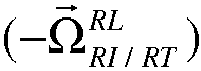
- the estimating device 5 further comprises a database 18, in which is stored a rotational speed vector - ⁇ ⁇ RI / RT RI of the Earth with respect to the inertial reference frame RI, that is to say of the reference frame RT with respect to the reference frame RI.
- the estimating device 5 further comprises a computer 20.
- the computer 20 is connected at the input to the inertial unit 7, to the network 13 of magnetometers 15 and to the database 18. It receives as input the vector instantaneous speed of rotation ⁇ ⁇ RL / RI RL measured by the gyrometer 9, the vector terrestrial magnetic field B RL measured by the network 13 of magnetometers 15 and the rotational speed vector - ⁇ ⁇ RI / RT RI of the Earth compared to the inertial reference frame RI stored in the database 18.
- the computer 20 is configured to estimate the orientation of the spacecraft 1 with respect to the inertial reference frame RI by calculating a passing matrix P RL / RI .
- the passage matrix P RL / RI defines the orientation of the spacecraft 1 with respect to the inertial reference system RI. It is calculated from the vector instantaneous speed of rotation ⁇ ⁇ RL / RI RL of the spacecraft 1.
- the computer 20 furthermore receives as input data enabling it to estimate a position vector X ⁇ RI RL of the spacecraft 1 with respect to the center of the inertial reference frame RI expressed in the reference frame RL.
- This data is for example the specific acceleration vector at RL compared to the reference frame RL measured by the accelerometer 11.
- the computer 20 is configured to calculate a specific acceleration vector at ⁇ RI RL relative to the inertial reference frame RI expressed in the reference frame RL from the specific acceleration vector at RL measured by the accelerometer 11, the passage matrix P RL / RI defining the orientation of the spacecraft 1 relative to the inertial reference system RI, and by projection on the axes of the reference frame RL.
- the computer 20 is further configured to estimate the position vector X ⁇ RI RL of the spacecraft 1 with respect to the center of the inertial reference frame RI expressed in the reference frame RL by double integration of the specific acceleration vector at ⁇ RI RL of the spacecraft 1 with respect to the inertial reference frame RI expressed in the reference frame RL compensated by the acceleration due to the gravity.
- the acceleration due to gravity is determined by a gravity model recorded in the database 18 and projected in the RL repository using the passage matrix P RL / RI .
- the position X ⁇ RI RL is estimated from ground-based observations, triangulation from known spatial or land positions, or any other known position estimation method.
- the input data received by the computer 20 is the speed vector d X ⁇ RL dt
- the computer 20 is connected at the output to a control unit 25 which is capable of modifying operating parameters of the spacecraft 1 as a function of the information received from the computer 20, and in particular of the estimated velocity vector d X ⁇ RL dt
- the control unit 25 is, alternatively or optionally, able to transmit, via a teletransmission means, for example an antenna, the estimated speed vector d X ⁇ RL dt
- the computer 20 is further able to calculate at any time the position vector X RI RL of the spacecraft 1 relative to the center of the reference frame RI, expressed in the reference frame RL by integration of the speed vector d X ⁇ RL dt
- the subject of the invention is also a method for estimating the speed vector d X ⁇ RL dt
- This estimation method comprises steps for determining input data and steps for estimating the velocity vector d X ⁇ RL dt
- the estimation device 5 according to the second embodiment differs from the estimation device 5 according to the first embodiment only in that the calculator 20 is configured to further estimate a second velocity vector V 2 of the spacecraft and a speed vector corrected V c .
- the velocity vector estimated by the calculator 20 by solving equation (1) is called the first velocity vector. V 1 .
- the second speed vector V 2 is estimated by a method different from that used to estimate the first velocity vector V 1 .
- the computer 20 is configured to estimate the second speed vector V 2 from the specific acceleration vector at RL from the accelerometer 11.
- it is suitable for calculating the specific acceleration vector at ⁇ RI RL relative to the inertial reference frame RI expressed in the reference frame RL from the specific acceleration vector at RL with respect to the reference frame RL and the estimation of the orientation of the spacecraft 1.
- the orientation of the spacecraft 1 is defined by the passage matrix P RL / RI . This matrix is obtained in a conventional manner from the measurements made by the gyrometer 9. It is further configured to estimate the second speed vector V 2 by integration of the specific acceleration vector at RL increased the acceleration due to gravity.
- the second speed vector V 2 is an estimate of the speed vector of the vehicle 1 relative to the inertial reference frame expressed in the reference frame RL related to the spacecraft.
- the computer 20 is further configured to combine the first speed vector V 1 and the second velocity vector V 2 using an algorithm adapted to deduce the corrected velocity vector V c .
- the computer 20 is for example configured to combine the first speed vector V 1 and the second velocity vector V 2 using an adapted Kalman filter taking into account the assumed or modeled stochastic characteristics of these two quantities.
- the computer 20 is configured to merge the first speed vector V 1 and the second velocity vector V 2 by particle filtering or by any other data fusion method adapted to give the corrected velocity vector V c .
- the speed vector corrected V c thus obtained constitutes a more accurate estimate of the real speed vector of the spacecraft 1 than the first and second speed vectors V 1 and V 2 alone.
- the figure 4 is a graph schematically representing the evolution over time of the error e 1 tainting the estimate of the first velocity vector V 1 estimate from the measurements made by the network 13 of magnetometers 15 and the error e 2 tainting the estimate of the second vector velocity V 2 , when the spacecraft 1 moves away from the Earth.
- the error e 2 does not depend on the position of the spacecraft 1 and in particular does not depend on the distance of the spacecraft 1 from the Earth. It increases linearly with time. It has been found that the error e 1 is constant over time. Its gradual increase on the graph of the figure 4 is due to the gradual decrease of the Earth's magnetic field gradient as the spacecraft moves away from the Earth.
- the relative positions of the curves representing e 1 and e 2 on the graph of the figure 4 define three operating areas of the estimation device 5 according to the second embodiment.
- a first operating zone called calibration phase C
- the error e 2 is smaller than the error e 1 .
- This operating zone corresponds to an initial flight phase of the spacecraft 1.
- the computer 20 is configured to estimate the error e 1 of the first velocity vector V 1 from the second velocity vector V 2 using a Kalman filter, least squares method or any other method of data fusion.
- the output of the data fusion algorithm provides an estimate of the corrected velocity vector V c .
- the error e 1 is smaller than the error e 2 .
- the computer 20 is configured to estimate the error e 2 of the second velocity vector V 2 from the first velocity vector V 1 using a Kalman filter, least squares method or any other method of data fusion.
- the output of the data fusion algorithm provides an estimate of the corrected velocity vector V c .
- the error e 1 is greater than the error e 2 , the distance from the Earth being such that the gradient of the earth's magnetic field becomes too small to allow an accurate estimation of the first vector velocity using magnetometric measurements.
- the estimation device 5 is configured to identify the speed vector of the vehicle 1 at the second speed vector V 2 , the error e 1 being too high.
- the equation 1 solved by the computer 20 to estimate the speed of the spacecraft was obtained by differentiation of the vector terrestrial magnetic field in the reference linked to the Earth, by using the stationarity of the Earth's magnetic field in the reference linked to the Earth to simplify the equality thus obtained, then by making repository changes so as to express the speed in the inertial reference according to the quantities measured by the on-board sensors aboard the spacecraft. It was possible to express the speed of the spacecraft in the inertial reference based on only known quantities or measurable by sensors.
- the invention has been described with reference to the Earth's magnetic field. However, the invention applies to any magnetic field produced by a star and stationary in a frame linked to this star.
Landscapes
- Engineering & Computer Science (AREA)
- Remote Sensing (AREA)
- Radar, Positioning & Navigation (AREA)
- Physics & Mathematics (AREA)
- General Physics & Mathematics (AREA)
- Automation & Control Theory (AREA)
- Aviation & Aerospace Engineering (AREA)
- Combustion & Propulsion (AREA)
- Chemical & Material Sciences (AREA)
- Electromagnetism (AREA)
- Life Sciences & Earth Sciences (AREA)
- Environmental & Geological Engineering (AREA)
- General Life Sciences & Earth Sciences (AREA)
- Geology (AREA)
- Navigation (AREA)
- Measuring Magnetic Variables (AREA)
Claims (12)
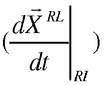
- Raumflugkörper (1), der mit einer Vorrichtung (5) zum Schätzen eines Geschwindigkeitsvektors
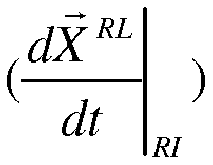
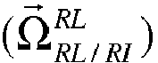
B RL ) zu messen, wobei der von dem Himmelskörper erzeugte Magnetfeldvektor (B RL ) in einem an den Himmelskörper gebundenen Bezugssystem (RT) stationär ist, und einen Rechner (20) umfasst, der ausgebildet ist, den Geschwindigkeitsvektor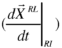

B RL ), der zeitlichen Ableitung

B RL ), einem Positionsvektor
- Raumflugkörper (1) nach Anspruch, bei dem der Rechner (20) ausgebildet ist, den Geschwindigkeitsvektor


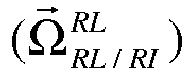
B RL der Magnetfeldvektor ist, ausgedrückt in dem an den Raumflugkörper (RL) gebundenen Bezugssystem und erhalten aus dem von mindestens einem der Magnetometer durchgeführten Messungen;
B RL ) ist, ausgedrückt in dem an den Raumflugkörper gebundenen Bezugssystem (RL) und abgeleitet vom Magnetfeldvektor (B RL ), der von mindestens einem der Magnetometer (15) gemessen wurde;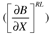
B RL ) ist, ausgedrückt in dem an den Raumflugkörper gebundenen Bezugssystem (RL) und abgeleitet vom Magnetfeldvektor (B RL ), der von dem Netz (13) an Magnetometern (15) gemessen wird;

- Raumflugkörper (1) nach einem der Ansprüche 1 und 2, bei dem die Schätzvorrichtung (5) außerdem einen Beschleunigungssensor (11) umfasst, der geeignet ist, einen spezifischen Beschleunigungsvektor (
a RL ) des Raumflugkörpers (1) in Bezug auf das an den Raumflugkörper gebundene Bezugssystem zu messen, wobei der Rechner (20) geeignet ist, einen spezifischen Beschleunigungsvektor


- Raumflugkörper (1) nach einem beliebigen der vorhergehenden Ansprüche, wobei der Raumflugkörper (1) eine Trägerrakete ist.
- Raumflugkörper (1) nach einem beliebigen der vorhergehenden Ansprüche, bei dem der Himmelskörper die Erde ist und bei dem das Magnetfeld (
B RL ) das Erdmagnetfeld ist. - Raumflugkörper (1) nach Anspruch 5, bei dem das an den Himmelskörper gebundene Bezugssystem (RT) ein geozentrisches äquatoriales Bezugssystem ist, das mit der Erde dreht und einen mit dem Massezentrum (O) der Erde übereinstimmenden Ursprungspunkt, eine Achse (ART), die in der Ebene des Äquators (E) enthalten ist und durch einen Schnittpunkt des Äquators (E) mit einem Referenzmeridian (M) hindurchgeht, eine Achse (CRT), die mit der Achse (A) der mittleren Erddrehung übereinstimmt, und eine Achse (BRT), die in direkter Weise das an die Erde gebundene Bezugssystem vervollständigt, umfasst, und das Trägheitsbezugssystem (RI) ein geozentrisches äquatoriales Trägheitsbezugssystem ist, das einen mit dem Massezentrum der Erde übereinstimmenden Ursprungspunkt und eine Achse (ARI), die zu einem entfernten Fixstern gerichtet ist, eine Achse (CRI), die mit der Achse der mittleren Erddrehung (A) übereinstimmt, und eine Achse (BRI), die zu einem entfernten Fixstern gerichtet ist und in direkter Weise das Trägheitsbezugssystem (RI) vervollständigt, umfasst.
- Raumflugkörper (1) nach einem beliebigen der vorhergehenden Ansprüche, bei dem das Netz (13) an Magnetometern (15) vier Magnetometer umfasst, wobei die Positionierung der Magnetometer (15) an dem Raumflugkörper (1) so gewählt ist, dass der Abstand zwischen den Magnetometern (15) maximiert wird.
- Raumflugkörper (1) nach Anspruch 7, bei dem die Magnetometer an den Scheitelpunkten eines Polyeders angeordnet sind.
- Raumflugkörper (1) nach einem beliebigen der vorhergehenden Ansprüche, bei dem die Schätzvorrichtung (5) einen Beschleunigungssensor (11) umfasst, der geeignet ist, einen spezifischen Beschleunigungsvektor (
a RL ) des Raumflugkörpers (1) in Bezug auf das an den Raumflugkörper gebundene Bezugssystem zu messen, wobei der Rechner (20) geeignet ist, einen spezifischen Beschleunigungsvektor
V 2) des Raumflugkörpers (1) in Bezug auf das Trägheitsbezugssystem (RI) durch Integration des spezifischen Beschleunigungsvektors
V 2) und den Geschwindigkeitsvektor (V 1), der aus der Messung des von dem Himmelskörper (B ) erzeugten Magnetfeldes geschätzt ist, gemäß einem vorbestimmten Algorithmus zu kombinieren, um daraus einen korrigierten Geschwindigkeitsvektor (V c ) des Raumflugkörpers (1) herzuleiten. - Verfahren zum Schätzen eines Geschwindigkeitsvektors
 - Bestimmen des Vektors der momentanen Drehgeschwindigkeit
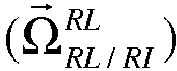 - Bestimmen des durch den Himmelskörper (
B RL ) erzeugten Magnetfeldvektors mittels Messungen, die von einem Netz (13) an Magnetometern (15) durchgeführt werden;- Schätzen des Positionsvektors (XRI) des Raumflugkörpers (1) mittels eines Rechners (20) in Bezug auf das Zentrum des Bezugssystems (RI) aus einer am Rechner (20) eingangsseitig empfangenen Datengröße;- Schätzen des Geschwindigkeitsvektors
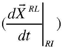


B RL ), der zeitlichen Ableitung

B RL ) verknüpft. - Verfahren zum Schätzen nach Anspruch 10, bei dem der Geschwindigkeitsvektor


B RL der Magnetfeldvektor ist, ausgedrückt in dem an den Raumflugkörper (RL) gebundenen Bezugssystem und erhalten aus dem von mindestens einem der Magnetometer durchgeführten Messungen;
B RL ) ist, ausgedrückt in dem an den Raumflugkörper gebundenen Bezugssystem (RL) und abgeleitet vom Magnetfeldvektor (B RL ), der von mindestens einem der Magnetometer (15) gemessen wurde;
B RL ) ist, ausgedrückt in dem an den Raumflugkörper gebundenen Bezugssystem (RL) und abgeleitet vom Magnetfeldvektor (B RL ), der von dem Netz (13) an Magnetometern (15) gemessen wird;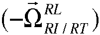

- Verfahren zum Bestimmen eines korrigierten Geschwindigkeitsvektors (
V c ) eines Raumflugkörpers nach Anspruch 9, die Schritte umfassend:- Schätzen eines ersten Geschwindigkeitsvektors (V 1) des Raumflugkörpers (1), wobei das Schätzverfahren nach Anspruch 10 durchgeführt wird;- Schätzen eines zweiten Geschwindigkeitsvektors (V 2) des Raumflugkörpers (1) aus dem spezifischen Beschleunigungsvektor (a RL ) des Raumflugkörpers (1) in Bezug auf das an den Raumflugkörper gebundene Bezugssystem (RL), der mittels des Beschleunigungssensors (11) der Schätzvorrichtung (5) gemessen wird; und- Kombinieren des ersten geschätzten Geschwindigkeitsvektors (V 1) und des zweiten geschätzten Geschwindigkeitsvektors (V 2) des Raumflugzeugs (1), wobei ein vorbestimmter Algorithmus ausgeführt wird, um daraus den korrigierten Geschwindigkeitsvektor (V c ) des Raumflugkörpers (1) herzuleiten.
Applications Claiming Priority (1)
| Application Number | Priority Date | Filing Date | Title |
|---|---|---|---|
| FR1101999A FR2977313B1 (fr) | 2011-06-28 | 2011-06-28 | Engin spatial muni d'un dispositif d'estimation d'un vecteur vitesse et procede d'estimation correspondant |
Publications (2)
| Publication Number | Publication Date |
|---|---|
| EP2541199A1 EP2541199A1 (de) | 2013-01-02 |
| EP2541199B1 true EP2541199B1 (de) | 2017-07-12 |
Family
ID=46317289
Family Applications (1)
| Application Number | Title | Priority Date | Filing Date |
|---|---|---|---|
| EP12173874.4A Active EP2541199B1 (de) | 2011-06-28 | 2012-06-27 | Raumschiff, das mit einer Vorrichtung zum Schätzen seines Geschwindigkeitsvektors in Bezug auf ein Inertialsystem ausgestattet ist, und entsprechendes Schätzverfahren |
Country Status (2)
| Country | Link |
|---|---|
| EP (1) | EP2541199B1 (de) |
| FR (1) | FR2977313B1 (de) |
Families Citing this family (14)
| Publication number | Priority date | Publication date | Assignee | Title |
|---|---|---|---|---|
| DE102014211283B4 (de) | 2013-06-14 | 2022-10-13 | Deutsches Zentrum für Luft- und Raumfahrt e.V. | Vorrichtung zur Navigation innerhalb von Bereichen, die einem Magnetfeld ausgesetzt sind |
| US9857179B2 (en) * | 2014-12-30 | 2018-01-02 | Northrop Grumman Systems Corporation | Magnetic anomaly tracking for an inertial navigation system |
| FR3050524B1 (fr) * | 2016-04-20 | 2019-08-16 | Sysnav | Procede d'estimation du mouvement d'un objet evoluant dans un champ magnetique |
| FR3069053B1 (fr) * | 2017-07-13 | 2020-10-16 | Sysnav | Procede d'estimation du mouvement d'un objet evoluant dans un champ magnetique |
| FR3069317B1 (fr) * | 2017-07-21 | 2020-10-16 | Sysnav | Procede d'estimation du mouvement d'un objet evoluant dans un environnement et un champ magnetique |
| FR3069316B1 (fr) | 2017-07-21 | 2019-08-16 | Sysnav | Procede d'estimation du mouvement d'un objet evoluant dans un champ magnetique |
| FR3069649B1 (fr) | 2017-07-26 | 2021-01-01 | Sysnav | Procede de calibration d'un magnetometre |
| CN113282097B (zh) * | 2021-06-04 | 2022-07-29 | 中国人民解放军战略支援部队航天工程大学 | 一种geo博弈航天器相对位置非球形摄动误差的控制方法 |
| CN115060256B (zh) * | 2022-07-05 | 2022-11-08 | 西北工业大学 | 一种基于发射坐标系的制导炮弹空中姿态辨识方法 |
| FR3137764B1 (fr) | 2022-07-08 | 2024-07-12 | Sysnav | Procédé de recalage d’une attitude fournie par un système de navigation à l’estime au moyen d’un système de positionnement relatif |
| FR3142246A1 (fr) | 2022-11-18 | 2024-05-24 | Sysnav | Procédé d’estimation de l’évolution d’une vitesse d’un point de mesure |
| CN115790589B (zh) * | 2023-01-09 | 2023-05-02 | 西北工业大学 | 一种发射系无误差捷联惯性导航方法 |
| FR3165771A1 (fr) | 2024-09-03 | 2026-03-06 | Sysnav | Procédé de discrimination entre une foulée de marche et une foulée de course d’un piéton en déplacement |
| CN119714306B (zh) * | 2024-10-29 | 2026-03-24 | 北京控制工程研究所 | 一种小天体着陆过程中利用ToF相机的飞行器定位方法 |
Family Cites Families (2)
| Publication number | Priority date | Publication date | Assignee | Title |
|---|---|---|---|---|
| FR2914739B1 (fr) * | 2007-04-03 | 2009-07-17 | David Jean Vissiere | Systeme fournissant vitesse et position d'un corps en utilisant les variations du champ magnetique evaluees grace aux mesures de un ou des magnetiometres et de une ou des centrales inertielles |
| FR2922300B1 (fr) * | 2007-10-12 | 2009-11-20 | Saint Louis Inst | PROCEDE DE DETERMINATION DE l'ATTITUDE, DE LA POSITION ET DE LA VITESSE D'UN ENGIN MOBILE |
-
2011
- 2011-06-28 FR FR1101999A patent/FR2977313B1/fr not_active Expired - Fee Related
-
2012
- 2012-06-27 EP EP12173874.4A patent/EP2541199B1/de active Active
Also Published As
| Publication number | Publication date |
|---|---|
| EP2541199A1 (de) | 2013-01-02 |
| FR2977313B1 (fr) | 2013-08-09 |
| FR2977313A1 (fr) | 2013-01-04 |
Similar Documents
| Publication | Publication Date | Title |
|---|---|---|
| EP2541199A1 (de) | Raumschiff, das mit einer Vorrichtung zum Schätzen seines Geschwindigkeitsvektors in Bezug auf ein Inertialsystem ausgestattet ist, und entsprechendes Schätzverfahren | |
| EP1724592B1 (de) | System zur Schätzung der Geschwindigkeit eines Luftschiffs und Anwendung dieses Systems auf die Erfassung von Hindernissen | |
| EP0875002B1 (de) | Flugzeugsteuerhilfssystem mit head-up anzeigevorrichtung | |
| FR2953284A1 (fr) | Systeme et procede d'aide au conducteur d'un vehicule a entrainement biomecanique comprenant au moins une roue | |
| EP2385346B1 (de) | Verarbeitungsverfahren einer Navigationsphase in einem Navigationssystem, das eine Geländekorrelation einschließt | |
| EP1819984B1 (de) | Hybrides trägheitsnavigationssystem auf der basis eines kinematischen modells | |
| EP3447654B1 (de) | Bestimmungsverfahren der bewegungsbahn eines beweglichen objekts, programm und vorrichtung zur umsetzung dieses verfahrens | |
| CA2929198A1 (fr) | Procede de calcul de la vitesse surface d'au moins un navire et procede de deduction de chaque vecteur derive en tout point de la trajectoire dudit navire | |
| FR2922300A1 (fr) | PROCEDE DE DETERMINATION DE l'ATTITUDE, DE LA POSITION ET DE LA VITESSE D'UN ENGIN MOBILE | |
| FR2950438A1 (fr) | Localisation tridimensionnelle de zone cible terrestre par fusion d'images prises par deux capteurs satellitaires | |
| FR3064350A1 (fr) | Procede de calcul d'une vitesse d'un aeronef, procede de calcul d'un rayon de protection, systeme de positionnement et aeronef associes | |
| EP2500750A1 (de) | Verfahren und Vorrichtung zur Eichung eines Empfängers | |
| EP1205732B1 (de) | Inertialnavigationseinheit mit integriertem GPS-Empfänger | |
| JP2009220622A (ja) | 中高度人工衛星捕捉方法及び装置 | |
| WO2011039457A1 (fr) | Procédé et dispositif de localisation dynamique d'un mobile | |
| FR3060178A1 (fr) | Dispositif electronique de pilotage d'un drone, drone, procede de pilotage et programme d'ordinateur associes | |
| EP2410293B1 (de) | Harmonisierungsverfahren und -system eines Referenzsystems eines Winkelpositionierers in Bezug auf ein Erdbezugssystem | |
| CA3100115C (fr) | Procede d'harmonisation de deux unites de mesure inertielle l'une avec l'autre et systeme de navigation mettant en oeuvre ce procede | |
| Farroni et al. | A comparison among different methods to estimate vehicle sideslip angle | |
| EP4217681B1 (de) | Verfahren zur aktualisierung einer vielzahl von landmarken und zugehöriges computerprogrammprodukt und aktualisierungsvorrichtung | |
| EP3899432A1 (de) | Verfahren zur charakterisierung eines trägheitsnavigationssystems | |
| FR3071624B1 (fr) | Systeme d'affichage, procede d'affichage et programme d'ordinateur associes | |
| EP0389318B1 (de) | Navigationshilfsvorrichtung und terrestrisches Navigationssystem | |
| FR3041769A1 (fr) | Procede de geolocalisation | |
| EP4430362B1 (de) | Hybrides trägheits-/sternnavigationsverfahren mit harmonisierungsleistungsindikator |
Legal Events
| Date | Code | Title | Description |
|---|---|---|---|
| PUAI | Public reference made under article 153(3) epc to a published international application that has entered the european phase |
Free format text: ORIGINAL CODE: 0009012 |
|
| AK | Designated contracting states |
Kind code of ref document: A1 Designated state(s): AL AT BE BG CH CY CZ DE DK EE ES FI FR GB GR HR HU IE IS IT LI LT LU LV MC MK MT NL NO PL PT RO RS SE SI SK SM TR |
|
| AX | Request for extension of the european patent |
Extension state: BA ME |
|
| 17P | Request for examination filed |
Effective date: 20121224 |
|
| RAP1 | Party data changed (applicant data changed or rights of an application transferred) |
Owner name: SYSNAV Owner name: CENTRE NATIONAL D'ETUDES SPATIALES |
|
| GRAP | Despatch of communication of intention to grant a patent |
Free format text: ORIGINAL CODE: EPIDOSNIGR1 |
|
| RIC1 | Information provided on ipc code assigned before grant |
Ipc: B64G 1/28 20060101ALI20161222BHEP Ipc: G01C 21/08 20060101ALI20161222BHEP Ipc: F41G 7/00 20060101ALI20161222BHEP Ipc: G01C 21/16 20060101AFI20161222BHEP Ipc: B64G 1/36 20060101ALI20161222BHEP Ipc: B64G 1/24 20060101ALI20161222BHEP |
|
| INTG | Intention to grant announced |
Effective date: 20170126 |
|
| GRAS | Grant fee paid |
Free format text: ORIGINAL CODE: EPIDOSNIGR3 |
|
| GRAF | Information related to payment of grant fee modified |
Free format text: ORIGINAL CODE: EPIDOSCIGR3 |
|
| GRAA | (expected) grant |
Free format text: ORIGINAL CODE: 0009210 |
|
| AK | Designated contracting states |
Kind code of ref document: B1 Designated state(s): AL AT BE BG CH CY CZ DE DK EE ES FI FR GB GR HR HU IE IS IT LI LT LU LV MC MK MT NL NO PL PT RO RS SE SI SK SM TR |
|
| REG | Reference to a national code |
Ref country code: GB Ref legal event code: FG4D Free format text: NOT ENGLISH |
|
| REG | Reference to a national code |
Ref country code: CH Ref legal event code: EP |
|
| REG | Reference to a national code |
Ref country code: AT Ref legal event code: REF Ref document number: 908776 Country of ref document: AT Kind code of ref document: T Effective date: 20170715 |
|
| REG | Reference to a national code |
Ref country code: IE Ref legal event code: FG4D Free format text: LANGUAGE OF EP DOCUMENT: FRENCH |
|
| REG | Reference to a national code |
Ref country code: DE Ref legal event code: R096 Ref document number: 602012034357 Country of ref document: DE |
|
| REG | Reference to a national code |
Ref country code: NL Ref legal event code: MP Effective date: 20170712 |
|
| REG | Reference to a national code |
Ref country code: LT Ref legal event code: MG4D |
|
| REG | Reference to a national code |
Ref country code: AT Ref legal event code: MK05 Ref document number: 908776 Country of ref document: AT Kind code of ref document: T Effective date: 20170712 |
|
| PG25 | Lapsed in a contracting state [announced via postgrant information from national office to epo] |
Ref country code: NO Free format text: LAPSE BECAUSE OF FAILURE TO SUBMIT A TRANSLATION OF THE DESCRIPTION OR TO PAY THE FEE WITHIN THE PRESCRIBED TIME-LIMIT Effective date: 20171012 Ref country code: NL Free format text: LAPSE BECAUSE OF FAILURE TO SUBMIT A TRANSLATION OF THE DESCRIPTION OR TO PAY THE FEE WITHIN THE PRESCRIBED TIME-LIMIT Effective date: 20170712 Ref country code: LT Free format text: LAPSE BECAUSE OF FAILURE TO SUBMIT A TRANSLATION OF THE DESCRIPTION OR TO PAY THE FEE WITHIN THE PRESCRIBED TIME-LIMIT Effective date: 20170712 Ref country code: HR Free format text: LAPSE BECAUSE OF FAILURE TO SUBMIT A TRANSLATION OF THE DESCRIPTION OR TO PAY THE FEE WITHIN THE PRESCRIBED TIME-LIMIT Effective date: 20170712 Ref country code: SE Free format text: LAPSE BECAUSE OF FAILURE TO SUBMIT A TRANSLATION OF THE DESCRIPTION OR TO PAY THE FEE WITHIN THE PRESCRIBED TIME-LIMIT Effective date: 20170712 Ref country code: FI Free format text: LAPSE BECAUSE OF FAILURE TO SUBMIT A TRANSLATION OF THE DESCRIPTION OR TO PAY THE FEE WITHIN THE PRESCRIBED TIME-LIMIT Effective date: 20170712 Ref country code: AT Free format text: LAPSE BECAUSE OF FAILURE TO SUBMIT A TRANSLATION OF THE DESCRIPTION OR TO PAY THE FEE WITHIN THE PRESCRIBED TIME-LIMIT Effective date: 20170712 |
|
| PG25 | Lapsed in a contracting state [announced via postgrant information from national office to epo] |
Ref country code: IS Free format text: LAPSE BECAUSE OF FAILURE TO SUBMIT A TRANSLATION OF THE DESCRIPTION OR TO PAY THE FEE WITHIN THE PRESCRIBED TIME-LIMIT Effective date: 20171112 Ref country code: RS Free format text: LAPSE BECAUSE OF FAILURE TO SUBMIT A TRANSLATION OF THE DESCRIPTION OR TO PAY THE FEE WITHIN THE PRESCRIBED TIME-LIMIT Effective date: 20170712 Ref country code: ES Free format text: LAPSE BECAUSE OF FAILURE TO SUBMIT A TRANSLATION OF THE DESCRIPTION OR TO PAY THE FEE WITHIN THE PRESCRIBED TIME-LIMIT Effective date: 20170712 Ref country code: LV Free format text: LAPSE BECAUSE OF FAILURE TO SUBMIT A TRANSLATION OF THE DESCRIPTION OR TO PAY THE FEE WITHIN THE PRESCRIBED TIME-LIMIT Effective date: 20170712 Ref country code: BG Free format text: LAPSE BECAUSE OF FAILURE TO SUBMIT A TRANSLATION OF THE DESCRIPTION OR TO PAY THE FEE WITHIN THE PRESCRIBED TIME-LIMIT Effective date: 20171012 Ref country code: PL Free format text: LAPSE BECAUSE OF FAILURE TO SUBMIT A TRANSLATION OF THE DESCRIPTION OR TO PAY THE FEE WITHIN THE PRESCRIBED TIME-LIMIT Effective date: 20170712 Ref country code: GR Free format text: LAPSE BECAUSE OF FAILURE TO SUBMIT A TRANSLATION OF THE DESCRIPTION OR TO PAY THE FEE WITHIN THE PRESCRIBED TIME-LIMIT Effective date: 20171013 |
|
| REG | Reference to a national code |
Ref country code: DE Ref legal event code: R097 Ref document number: 602012034357 Country of ref document: DE |
|
| PG25 | Lapsed in a contracting state [announced via postgrant information from national office to epo] |
Ref country code: CZ Free format text: LAPSE BECAUSE OF FAILURE TO SUBMIT A TRANSLATION OF THE DESCRIPTION OR TO PAY THE FEE WITHIN THE PRESCRIBED TIME-LIMIT Effective date: 20170712 Ref country code: RO Free format text: LAPSE BECAUSE OF FAILURE TO SUBMIT A TRANSLATION OF THE DESCRIPTION OR TO PAY THE FEE WITHIN THE PRESCRIBED TIME-LIMIT Effective date: 20170712 Ref country code: DK Free format text: LAPSE BECAUSE OF FAILURE TO SUBMIT A TRANSLATION OF THE DESCRIPTION OR TO PAY THE FEE WITHIN THE PRESCRIBED TIME-LIMIT Effective date: 20170712 |
|
| PLBE | No opposition filed within time limit |
Free format text: ORIGINAL CODE: 0009261 |
|
| STAA | Information on the status of an ep patent application or granted ep patent |
Free format text: STATUS: NO OPPOSITION FILED WITHIN TIME LIMIT |
|
| PG25 | Lapsed in a contracting state [announced via postgrant information from national office to epo] |
Ref country code: IT Free format text: LAPSE BECAUSE OF FAILURE TO SUBMIT A TRANSLATION OF THE DESCRIPTION OR TO PAY THE FEE WITHIN THE PRESCRIBED TIME-LIMIT Effective date: 20170712 Ref country code: EE Free format text: LAPSE BECAUSE OF FAILURE TO SUBMIT A TRANSLATION OF THE DESCRIPTION OR TO PAY THE FEE WITHIN THE PRESCRIBED TIME-LIMIT Effective date: 20170712 Ref country code: SK Free format text: LAPSE BECAUSE OF FAILURE TO SUBMIT A TRANSLATION OF THE DESCRIPTION OR TO PAY THE FEE WITHIN THE PRESCRIBED TIME-LIMIT Effective date: 20170712 Ref country code: SM Free format text: LAPSE BECAUSE OF FAILURE TO SUBMIT A TRANSLATION OF THE DESCRIPTION OR TO PAY THE FEE WITHIN THE PRESCRIBED TIME-LIMIT Effective date: 20170712 |
|
| 26N | No opposition filed |
Effective date: 20180413 |
|
| REG | Reference to a national code |
Ref country code: FR Ref legal event code: PLFP Year of fee payment: 7 |
|
| PG25 | Lapsed in a contracting state [announced via postgrant information from national office to epo] |
Ref country code: SI Free format text: LAPSE BECAUSE OF FAILURE TO SUBMIT A TRANSLATION OF THE DESCRIPTION OR TO PAY THE FEE WITHIN THE PRESCRIBED TIME-LIMIT Effective date: 20170712 |
|
| REG | Reference to a national code |
Ref country code: DE Ref legal event code: R082 Ref document number: 602012034357 Country of ref document: DE Representative=s name: PRINZ & PARTNER MBB PATENTANWAELTE RECHTSANWAE, DE |
|
| PG25 | Lapsed in a contracting state [announced via postgrant information from national office to epo] |
Ref country code: MT Free format text: LAPSE BECAUSE OF FAILURE TO SUBMIT A TRANSLATION OF THE DESCRIPTION OR TO PAY THE FEE WITHIN THE PRESCRIBED TIME-LIMIT Effective date: 20170712 |
|
| REG | Reference to a national code |
Ref country code: CH Ref legal event code: PL |
|
| REG | Reference to a national code |
Ref country code: BE Ref legal event code: MM Effective date: 20180630 |
|
| PG25 | Lapsed in a contracting state [announced via postgrant information from national office to epo] |
Ref country code: LU Free format text: LAPSE BECAUSE OF NON-PAYMENT OF DUE FEES Effective date: 20180627 Ref country code: MC Free format text: LAPSE BECAUSE OF FAILURE TO SUBMIT A TRANSLATION OF THE DESCRIPTION OR TO PAY THE FEE WITHIN THE PRESCRIBED TIME-LIMIT Effective date: 20170712 |
|
| REG | Reference to a national code |
Ref country code: IE Ref legal event code: MM4A |
|
| PG25 | Lapsed in a contracting state [announced via postgrant information from national office to epo] |
Ref country code: CH Free format text: LAPSE BECAUSE OF NON-PAYMENT OF DUE FEES Effective date: 20180630 Ref country code: LI Free format text: LAPSE BECAUSE OF NON-PAYMENT OF DUE FEES Effective date: 20180630 Ref country code: IE Free format text: LAPSE BECAUSE OF NON-PAYMENT OF DUE FEES Effective date: 20180627 |
|
| PG25 | Lapsed in a contracting state [announced via postgrant information from national office to epo] |
Ref country code: BE Free format text: LAPSE BECAUSE OF NON-PAYMENT OF DUE FEES Effective date: 20180630 |
|
| PG25 | Lapsed in a contracting state [announced via postgrant information from national office to epo] |
Ref country code: TR Free format text: LAPSE BECAUSE OF FAILURE TO SUBMIT A TRANSLATION OF THE DESCRIPTION OR TO PAY THE FEE WITHIN THE PRESCRIBED TIME-LIMIT Effective date: 20170712 |
|
| PG25 | Lapsed in a contracting state [announced via postgrant information from national office to epo] |
Ref country code: HU Free format text: LAPSE BECAUSE OF FAILURE TO SUBMIT A TRANSLATION OF THE DESCRIPTION OR TO PAY THE FEE WITHIN THE PRESCRIBED TIME-LIMIT; INVALID AB INITIO Effective date: 20120627 Ref country code: PT Free format text: LAPSE BECAUSE OF FAILURE TO SUBMIT A TRANSLATION OF THE DESCRIPTION OR TO PAY THE FEE WITHIN THE PRESCRIBED TIME-LIMIT Effective date: 20170712 |
|
| PG25 | Lapsed in a contracting state [announced via postgrant information from national office to epo] |
Ref country code: MK Free format text: LAPSE BECAUSE OF NON-PAYMENT OF DUE FEES Effective date: 20170712 Ref country code: CY Free format text: LAPSE BECAUSE OF FAILURE TO SUBMIT A TRANSLATION OF THE DESCRIPTION OR TO PAY THE FEE WITHIN THE PRESCRIBED TIME-LIMIT Effective date: 20170712 |
|
| PG25 | Lapsed in a contracting state [announced via postgrant information from national office to epo] |
Ref country code: AL Free format text: LAPSE BECAUSE OF FAILURE TO SUBMIT A TRANSLATION OF THE DESCRIPTION OR TO PAY THE FEE WITHIN THE PRESCRIBED TIME-LIMIT Effective date: 20170712 |
|
| PGFP | Annual fee paid to national office [announced via postgrant information from national office to epo] |
Ref country code: DE Payment date: 20250620 Year of fee payment: 14 |
|
| PGFP | Annual fee paid to national office [announced via postgrant information from national office to epo] |
Ref country code: GB Payment date: 20260629 Year of fee payment: 15 |
|
| PGFP | Annual fee paid to national office [announced via postgrant information from national office to epo] |
Ref country code: FR Payment date: 20260629 Year of fee payment: 15 |