EP2543458B1 - Procédé de fabrication de composant de caméra endoscopique - Google Patents
Procédé de fabrication de composant de caméra endoscopique Download PDFInfo
- Publication number
- EP2543458B1 EP2543458B1 EP12175584.7A EP12175584A EP2543458B1 EP 2543458 B1 EP2543458 B1 EP 2543458B1 EP 12175584 A EP12175584 A EP 12175584A EP 2543458 B1 EP2543458 B1 EP 2543458B1
- Authority
- EP
- European Patent Office
- Prior art keywords
- metal blank
- lens holder
- machining
- brown
- lens
- Prior art date
- Legal status (The legal status is an assumption and is not a legal conclusion. Google has not performed a legal analysis and makes no representation as to the accuracy of the status listed.)
- Active
Links
Images


Classifications
-
- A—HUMAN NECESSITIES
- A61—MEDICAL OR VETERINARY SCIENCE; HYGIENE
- A61B—DIAGNOSIS; SURGERY; IDENTIFICATION
- A61B1/00—Instruments for performing medical examinations of the interior of cavities or tubes of the body by visual or photographical inspection, e.g. endoscopes; Illuminating arrangements therefor
- A61B1/00064—Constructional details of the endoscope body
- A61B1/0011—Manufacturing of endoscope parts
-
- A—HUMAN NECESSITIES
- A61—MEDICAL OR VETERINARY SCIENCE; HYGIENE
- A61B—DIAGNOSIS; SURGERY; IDENTIFICATION
- A61B1/00—Instruments for performing medical examinations of the interior of cavities or tubes of the body by visual or photographical inspection, e.g. endoscopes; Illuminating arrangements therefor
- A61B1/00064—Constructional details of the endoscope body
- A61B1/00071—Insertion part of the endoscope body
- A61B1/0008—Insertion part of the endoscope body characterised by distal tip features
- A61B1/00096—Optical elements
-
- A—HUMAN NECESSITIES
- A61—MEDICAL OR VETERINARY SCIENCE; HYGIENE
- A61B—DIAGNOSIS; SURGERY; IDENTIFICATION
- A61B1/00—Instruments for performing medical examinations of the interior of cavities or tubes of the body by visual or photographical inspection, e.g. endoscopes; Illuminating arrangements therefor
- A61B1/00163—Optical arrangements
- A61B1/00188—Optical arrangements with focusing or zooming features
-
- B—PERFORMING OPERATIONS; TRANSPORTING
- B22—CASTING; POWDER METALLURGY
- B22F—WORKING METALLIC POWDER; MANUFACTURE OF ARTICLES FROM METALLIC POWDER; MAKING METALLIC POWDER; APPARATUS OR DEVICES SPECIALLY ADAPTED FOR METALLIC POWDER
- B22F3/00—Manufacture of workpieces or articles from metallic powder characterised by the manner of compacting or sintering; Apparatus specially adapted therefor ; Presses and furnaces
- B22F3/24—After-treatment of workpieces or articles
-
- B—PERFORMING OPERATIONS; TRANSPORTING
- B22—CASTING; POWDER METALLURGY
- B22F—WORKING METALLIC POWDER; MANUFACTURE OF ARTICLES FROM METALLIC POWDER; MAKING METALLIC POWDER; APPARATUS OR DEVICES SPECIALLY ADAPTED FOR METALLIC POWDER
- B22F5/00—Manufacture of workpieces or articles from metallic powder characterised by the special shape of the product
- B22F5/10—Manufacture of workpieces or articles from metallic powder characterised by the special shape of the product of articles with cavities or holes, not otherwise provided for in the preceding subgroups
-
- G—PHYSICS
- G02—OPTICS
- G02B—OPTICAL ELEMENTS, SYSTEMS OR APPARATUS
- G02B23/00—Telescopes, e.g. binoculars; Periscopes; Instruments for viewing the inside of hollow bodies; Viewfinders; Optical aiming or sighting devices
- G02B23/24—Instruments or systems for viewing the inside of hollow bodies, e.g. fibrescopes
- G02B23/2476—Non-optical details, e.g. housings, mountings, supports
-
- G—PHYSICS
- G02—OPTICS
- G02B—OPTICAL ELEMENTS, SYSTEMS OR APPARATUS
- G02B7/00—Mountings, adjusting means, or light-tight connections, for optical elements
- G02B7/02—Mountings, adjusting means, or light-tight connections, for optical elements for lenses
- G02B7/04—Mountings, adjusting means, or light-tight connections, for optical elements for lenses with mechanism for focusing or varying magnification
- G02B7/10—Mountings, adjusting means, or light-tight connections, for optical elements for lenses with mechanism for focusing or varying magnification by relative axial movement of several lenses, e.g. of varifocal objective lens
-
- Y—GENERAL TAGGING OF NEW TECHNOLOGICAL DEVELOPMENTS; GENERAL TAGGING OF CROSS-SECTIONAL TECHNOLOGIES SPANNING OVER SEVERAL SECTIONS OF THE IPC; TECHNICAL SUBJECTS COVERED BY FORMER USPC CROSS-REFERENCE ART COLLECTIONS [XRACs] AND DIGESTS
- Y10—TECHNICAL SUBJECTS COVERED BY FORMER USPC
- Y10T—TECHNICAL SUBJECTS COVERED BY FORMER US CLASSIFICATION
- Y10T29/00—Metal working
- Y10T29/49—Method of mechanical manufacture
- Y10T29/49826—Assembling or joining
-
- Y—GENERAL TAGGING OF NEW TECHNOLOGICAL DEVELOPMENTS; GENERAL TAGGING OF CROSS-SECTIONAL TECHNOLOGIES SPANNING OVER SEVERAL SECTIONS OF THE IPC; TECHNICAL SUBJECTS COVERED BY FORMER USPC CROSS-REFERENCE ART COLLECTIONS [XRACs] AND DIGESTS
- Y10—TECHNICAL SUBJECTS COVERED BY FORMER USPC
- Y10T—TECHNICAL SUBJECTS COVERED BY FORMER US CLASSIFICATION
- Y10T29/00—Metal working
- Y10T29/49—Method of mechanical manufacture
- Y10T29/4998—Combined manufacture including applying or shaping of fluent material
- Y10T29/49982—Coating
- Y10T29/49984—Coating and casting
-
- Y—GENERAL TAGGING OF NEW TECHNOLOGICAL DEVELOPMENTS; GENERAL TAGGING OF CROSS-SECTIONAL TECHNOLOGIES SPANNING OVER SEVERAL SECTIONS OF THE IPC; TECHNICAL SUBJECTS COVERED BY FORMER USPC CROSS-REFERENCE ART COLLECTIONS [XRACs] AND DIGESTS
- Y10—TECHNICAL SUBJECTS COVERED BY FORMER USPC
- Y10T—TECHNICAL SUBJECTS COVERED BY FORMER US CLASSIFICATION
- Y10T29/00—Metal working
- Y10T29/49—Method of mechanical manufacture
- Y10T29/4998—Combined manufacture including applying or shaping of fluent material
- Y10T29/49988—Metal casting
- Y10T29/49989—Followed by cutting or removing material
Definitions
- the present invention is generally related to a method of manufacturing endoscopic camera components and, more particularly, to a method of manufacturing lens holders for use in endoscopic cameras.
- Endoscopes and endoscopic video cameras are now widely used by physicians during surgery to view inside body cavities.
- small incisions called portals
- An endoscope or endoscopic video camera is inserted in one of the portals.
- Surgical instruments used to perform specific surgical tasks are inserted into other portals.
- the surgeon views the surgical site through the endoscope or endoscopic video camera to determine how to manipulate the surgical instruments in order to accomplish the surgical procedure.
- An advantage of performing endoscopic surgery is that, since the portions of the body that are cut open are minimized, the portions of the body that need to heal after surgery are likewise reduced.
- only relatively small portions of the patient's internal organs and tissues are exposed to the open environment. This minimal opening of the patient's body lessens the extent to which a patient's organs and tissues are open to infection.
- an endoscopic video camera contains an optical focusing lens and a focusing device that can be adjusted to optimize images transmitted by the endoscopic video camera.
- the focusing device usually utilizes magnetic drives to move or rotate the focusing lens axially within the lens holder.
- the lens holder is a small yet convoluted part of the endoscopic video camera.
- the endoscopic video cameras described in U.S. Pat. No. 5,359,992 issued to Hori et al. and U.S. Pat. No. 5,056,902 issued to Chinnock et al.
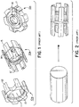
- a zoom lens holder 10a can be in the form of a raceway around the periphery of the lens (not shown) with a set of symmetrical protrusions or legs which are evenly spaced and extend proximally from the raceway in one direction which define the path of the lens during operation.
- a fixed lens holder 10b can be in the form of a raceway around the periphery of the lens with two sets of symmetrical protrusions or legs, with the first set of protrusions or legs extending proximally from the raceway in one direction, and the second set of protrusions or legs extending distally from the raceway in the opposite direction.
- Anhalt also discloses a simple lens holder 10c that does not contain any protrusions or legs extending from the raceway.
- the lens holders play an important role in the performance of the endoscopic video cameras, it is critical that the lens holders be manufactured with precision.
- the lens holders are manufactured from solid metal bar stocks by 100% machining, as illustrated in FIG. 2 .
- This manufacturing method unavoidably results in high manufacturing cost in terms of material used (and wasted) and the machining time. Using this manufacturing method, it is difficult, if not impossible, to machine the lens holders with consistent precision. Therefore, the traditional 100% machining is not suitable for a high volume production of the lens holders.
- MIM metal injection molding
- a metal powder is mixed with a binder to form a homogenous liquid mixture.
- the mixture is injected into a die or mold which is then subjected to high pressure to form a "green" metal blank, which typically is about 60% dense.
- the binder in the "green” metal blank is then burned off or removed chemically and the resulting skeleton, called “brown” metal blank, is sintered to near full density.
- the MIM process greatly saves the material used for manufacturing and allows a high volume production with reasonable consistency in quality.
- the MIM process is also versatile at producing small components having complex internal and external shapes.
- an improved manufacturing method for an endoscopic camera component such as a lens holder for an endoscope, which efficiently utilizes metal materials, minimizes secondary machining, shortens the overall manufacturing time, and increases consistency in the component quality. It is also desirable that such manufacturing method is sufficiently versatile to be applied to various types of lens holders and other similar types of metal components.
- EP 1 250 881 A2 discloses an endoscope with magnetic focusing.
- the idea relates to a magnetic drive focusing device with at least one lens within a chamber and an adjuster with magnets outside the chamber. Positioned between the lens and the chamber is a second sleeve with helical guide paths.
- the adjuster is moved outside the chamber, the magnetic field within the chamber causes the lens within the chamber to move.
- none-magnetic guides which ride in the helical guide paths farce the lens to move axially within the device.
- JP 11-089850 discloses the production of a cup-like colfecting blade body for tissue removal. Two blade bodies are molded before edging through a sintering treatment. Afterwards, the edges of the cup blades are subjected to an electrolytic polishing treatment for edging the blade bodies.
- the present invention provides a method of manufacturing an endoscope having at least one lens holder.
- the method comprises the steps of molding at least one brown metal blank by a metal injection molding (MIM) process, wherein the at least one brown metal blank has a sprue and a post, and is substantially similar in size and shape to the at least one lens holder, machining the at least one brown metal blank to form the at least one lens holder, installing a lens in each of the at least one lens holder, and assembling the at least one lens holder having the lens into an endoscopic tube to form an endoscope.
- MIM metal injection molding
- the at least one brown metal blank contains an outer shell which supports and strengthens the at least one brown metal blank from damage during the molding and machining steps. Machining the inside surfaces can be performed by holding the at least one brown metal blank from the outer shell.
- the outer shell also prevents deflecting the extrusions of the component during machining.
- the step of machining comprises the steps of machining the inside dimensions of the at least one brown metal blank, and then machining the outside dimensions of the at least one brown metal blank using the inside machined surfaces as a reference to form the at least one lens holder.
- the inside surfaces as a reference, the final outside surfaces can be precisely grinded to the final dimensions with tight tolerances.
- the machining step may start with machining the outer surfaces of the brown metal blank, followed by machining the inside surfaces.
- the sprue and the post of the at least one brown metal blank are trimmed for ease of handling before machining the at least one brown metal blank. This is a further aspect of the present invention.
- lubricants are applied to the at least one lens holder using Dicronite coating process before a lens is installed in the at least one lens holder.
- the present invention also provides an endoscope having at least one lens holder which comprises a body containing a sintered feedstock, a machined inside surface, and a machined outside surface.
- the body of the at least one lens holder has a raceway and a set of extrusions extending from the periphery of said raceway in one direction.
- the body of the at least one lens holder has a raceway, a first set of extrusions extending from the periphery of said raceway in one direction, and a second set of extrusions extending from the periphery of said raceway in an opposite direction.
- the present invention provides a method of manufacturing an endoscope having one or more lens holders.
- endoscope and “endoscopic video camera” are used interchangeably in this Application.
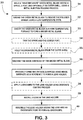
- FIG. 3 illustrates various steps of the manufacturing method 30 in accordance with the present invention.
- the first few of steps, 31 to 37, are devoted to the steps of manufacturing the lens holders which utilizes a near net machining concept.
- a metal blank also called MIM blank, which includes all molding features, e.g. gating, sprue, ejection pin marks, parting line, post, is first molded by a metal injection molding (MIM) process to a "near net shape" of the final component such that minimal secondary machining is required to complete the final component.
- MIM metal injection molding
- MIM process refers to the process which combines metal powders with binder materials to produce a 'feedstock' that is injected as a liquid into a hollow mold using plastic injection molding machines, followed by the binder removal and the sintering step to solidify the molded metal component.
- the MIM process is a superior process as compared to forging, casting, or other processes in that it allows an arbitrary selection of the shape of the metal body, including irregular shapes, and in that it is suitable for mass production at a lower cost, and in that the sintered product has excellent physical and mechanical properties as a result of the improved compaction obtained by use of fine powder.
- the MIM process can achieve tighter tolerance than other processes, e.g. casting, extrusion, or forging.
- the properties of the metal powders determine the final properties of the MIM product.
- Any metal or metal alloys capable of implementation within the MIM feedstock and responding to the magnet field created by external magnets can be used for fabricating the MIM blank for this invention.
- Suitable metal or metal alloys for the present invention include, but not limiting to, stainless steel, aluminum, nickel, brass, titanium, tantalum, iron, phosphor bronze, tungsten, gold, silver, copper, cobalt, chromium or alloys thereof.
- the preferred metal for the lens holders is magnetic stainless steel.
- near net shape means that the metal blank is substantially similar to the final component in terms of shapes and dimensions.
- the first step 31 is molding a "near net shape" green metal blank having a sprue, a post, and optionally an outer shell, using a metal injection molding process.
- the second step 32 is debinding the green metal blank to remove the polymer binder using a low temperature oven followed by step 33, sintering the green metal blank in high temperature furnace to fuse the metal powder together to form "near net shape" brown metal blank.
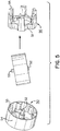
- FIGS. 4 to 6 illustrate different types of "near net shape" brown metal blanks having a sprue and a post during a manufacturing method in accordance with the present invention.
- FIG. 4 shows that a metal blank 40a,40b,40c which has an inner surface and an outer surface.
- the metal blank 40a,40b,40c has a center post 41,42,43 which is positioned in the center of the blank 40a,40b,40c and which forms an integrated part of the metal blank 40a,40b,40c.
- the metal blank 40a,40b,40c has a spruce (not shown) at the opposite end of the post 41,42,43.
- FIGS. 5 and 6 show that a metal blank 50,60 which has an inner surface and an outer surface.
- the metal blank 50,60 has a center post 52,62 and a spruce 53,63 which locates at the opposite end of the center post 52,62. Both the center post 52,62 and a spruce 53,63 form an integrated part of the metal blank 50,60.
- the center post 41,42,43,52,62 provides support to the center material of the metal blank 40a,40b,40c,50,60 and prevents it from slumping during the sintering step.
- the center post 41,42,43,52,62 and sprue 53,63 provides an additional means for handling the metal blank 40a,40b,40c,50,60 during the manufacturing process. For instance, they are able to set the blank 40a,40b,40c,50,60 in the sintering fixture without having the blank surface in touch of the fixture surface to avoid the constraints of shrinkage at the blank surface during sintering because of the friction between the blank surface and the fixture surface.
- the center post 41,42,43,52,62 extends beyond the bottom surface of the metal blank 40a,40b,40c,50,60 to provide sufficient clearance between the bottom surface of the metal blank and the surface of the sintering fixture.
- the metal blank 50,60 may optionally comprise an outer shell 54,64, which forms an integrated part of the metal blank 50,60.
- the outer shell 54,64 has an interior surface and an exterior surface.
- the interior surface of the outer shell 54,64 is in contact with the outer surface of the metal blank 50,60, and particularly, partial or all peripheries of the extrusions/legs 55,65,65' and the raceway 51,61 of the metal blank 50,60.
- the outer shell 54,64 substantially covers the rest parts of metal blank 50,60.
- the outer shell 54,64 provides advantageous structure support to the metal blank 50,60 during the sintering and machining steps.
- the outer shell prevents deflecting any extrusion of the component.
- the outer shell is beneficial when the lens holder has long extrusions/legs, e.g. the zoom lens holder in FIG. 5 and the fixed lens holder in FIG. 6 .
- the outer shell is not necessary, e.g. the various lens holders in FIG. 4 .
- the thickness of the outer shell 54,64 may vary, but necessarily depends on the type of metal used and the extent of secondary machining.
- the outer shell 54,64 should be sufficiently strong to stand the impacts from the secondary machining.
- the next step 34 is optional for the manufacturing method in accordance with the present invention.
- the sprue 53,63 and the post 52,62 are trimmed for ease of handling.
- the manufacturing method may optionally have the step 35 in which the metal blank 50,60 is held from the outer shell 54,64 for ease of handling, for example, during the step of machining the inside surface of the metal blank 50,60.
- steps 34 and 35 can be performed in reversed order.
- the metal blank 40a,40b,40c,50,60 is post machined to the required specifications of the lens holder 40d,40e,40f,56,66.
- machining or “machined” refers to the conventional metalworking processes such as heat treatments and/or surface treatments such as abrading, cutting, drilling, forming, grinding, and/or shaping of a piece of metal into the desired final piece using by machine tools such as lathes, power saws, and presses.
- the center post, and the outer shell if any, may be removed during the secondary machining or at the end of the machining, depending on the geometry of the component and the need to access to certain parts of the component.
- the metal blank 40a,40b,40c,50,60 is "near net shape" of the lens holder 40d,40e,40f,56,66, minimal machining is required to form the desired lens holder. Less machining means less machining time and lower manufacturing cost.
- the present method avoids material waste, saves machining time, and improves the quality consistency of the finished lens holders.
- the machining steps 36,37 are typically performed by the step of machining the inside dimensions of the metal blank 36, followed by the step of machining the outside dimensions of the metal blank using the inside machined surfaces of the metal blank 37.
- the inside surfaces By using the inside surfaces as a reference, the final outside surface can be precisely grinded to the final dimensions with tight tolerances which cannot be achieved by a direct molding process.
- Conventional Computer Numerical Controlled (CNC) milling is unable to accomplish the outside diameter as the interrupt cutting action will deflect any extrusions of the metal blank during the operation and affect the final dimensions.
- machining steps can be performed in a less preferred order, for instance, by the step of machining the outer surfaces of the metal blank first 37, followed by the step of machining the inner surfaces 36, and optionally using the outer surfaces as a reference, to form the lens holder.
- lubricants are applied to the lens holder using Dicronite coating process, step 38.
- a lens is installed in the lens holder, the step 39.
- the lens holder installed with the lens is assembled into an endoscopic tube to form an endoscope, the step 40.
- each lens holder can be manufactured in accordance with same or different embodiments of the present invention. Additionally, more than one lens may be installed in a lens holder and different type of lenses can be installed in the same or different lens holders.
- the present invention also provides an endoscope having one or more lens holders, wherein the lens holder comprises a body which in turn comprises a sintered feedstock, a machined inside surface, and a machined outside surface.
- the feedstock is preferably made by stainless steel.
- the lens holders of the present invention distinguish from the prior art lens holders in that the body of the lens holders of the present invention contains a sintered feedstock, whereas the body of the prior art lens holders is made up by 100% metal stock. Because the sintered feedstock has gone through a high temperature treatment during the sintering step in the MIM process, the properties of two bodies are different from each other. For instance, the sintered feedstock usually has a higher density and durability than that of the metal stock.
- a lens holder 40e,40f,56 has a raceway 45,46,51 with a set of symmetrical extrusions/legs 47,48,55 which are evenly spaced and extend from the raceway 45,46,51 in one direction.
- a lens holder 66 has a raceway 61 with two sets of symmetrical extrusions/legs 65,65' with the first set of extrusions/legs 65 extending proximally from raceway 61 in one direction, and the second set of extrusions/legs 65' extending distally from raceway 61 in the opposite direction.
- a simple lens holder 40d has no protrusions extending from the raceway 44. All these lens holders share two common structure features. First, their exterior shape, defined by the periphery of the raceway 44,45,46,51,61 and /or the extrusions/legs 447,48,55,65,65' is generally of cylinder shape, such that an outer shell of sleeve shape is able to cover the lens holders during the manufacturing steps. Second, they have a lengthwise hollow center for holding a lens.
Landscapes
- Health & Medical Sciences (AREA)
- Life Sciences & Earth Sciences (AREA)
- Engineering & Computer Science (AREA)
- Physics & Mathematics (AREA)
- Surgery (AREA)
- Optics & Photonics (AREA)
- Manufacturing & Machinery (AREA)
- Heart & Thoracic Surgery (AREA)
- General Health & Medical Sciences (AREA)
- Radiology & Medical Imaging (AREA)
- Nuclear Medicine, Radiotherapy & Molecular Imaging (AREA)
- Biomedical Technology (AREA)
- Biophysics (AREA)
- Medical Informatics (AREA)
- Molecular Biology (AREA)
- Animal Behavior & Ethology (AREA)
- Pathology (AREA)
- Public Health (AREA)
- Veterinary Medicine (AREA)
- Mechanical Engineering (AREA)
- Astronomy & Astrophysics (AREA)
- General Physics & Mathematics (AREA)
- Endoscopes (AREA)
- Instruments For Viewing The Inside Of Hollow Bodies (AREA)
Claims (10)
- Procédé de fabrication d'un endoscope comprenant au moins un porte-lentille, comprenant les étapes suivantes:mouler au moins une ébauche de métal brun en utilisant un procédé de moulage par injection, ladite au moins une ébauche de métal brun comprenant une busette, un montant et une coquille extérieure, ladite au moins une ébauche de métal brun présentant des dimensions intérieures et des dimensions extérieures, et ladite au moins une ébauche de métal brun présentant une taille et une forme similaires à celles dudit au moins un porte-lentille;tenir ladite au moins une ébauche de métal brun à l'écart de ladite coquille extérieure;usiner ladite au moins une ébauche de métal brun de manière à former ledit au moins un porte-lentille, dans lequel ladite busette, ledit montant et ladite coquille extérieure sont enlevés pendant ou à la fin de l'usinage;installer une lentille dans chacun desdits au moins un porte-lentille; etassembler ledit au moins un porte-lentille installé avec ladite lentille dans ledit endoscope.
- Procédé selon la revendication 1, dans lequel l'étape de moulage d'au moins une ébauche de métal brun comprend les étapes suivantes:former au moins une ébauche de métal vert en utilisant le moulage par injection de métal d'une charge d'alimentation comprenant des poudres métalliques et des liants polymères, ladite au moins une ébauche de métal vert comprenant une busette, un montant et une coquille extérieure, ladite au moins une ébauche de métal vert présentant des dimensions intérieures et des dimensions extérieures, et ladite au moins une ébauche de métal vert présentant une taille et une forme similaires à celles dudit au moins un porte-lentille;délianter ladite au moins une ébauche de métal vert afin d'éliminer lesdits liants polymères en utilisant un four à basse température pour obtenir au moins une ébauche de métal vert déliantée; etfritter ladite au moins une ébauche de métal vert déliantée dans un four à haute température pour obtenir ladite au moins une ébauche de métal brun.
- Procédé selon l'une quelconque des revendications précédentes, comprenant en outre, avant ladite étape d'usinage de ladite au moins une ébauche de métal brun, l'étape d'ébarbage de ladite busette et dudit montant de ladite au moins une ébauche de métal brun.
- Procédé selon l'une quelconque des revendications précédentes, dans lequel ladite étape d'usinage de ladite au moins une ébauche de métal brun pour former ledit au moins un porte-lentille comprend les étapes suivantes:usiner lesdites dimensions intérieures de ladite au moins une ébauche de métal brun; etusiner lesdites dimensions extérieures de ladite au moins une ébauche de métal brun en utilisant lesdites dimensions intérieures de ladite au moins une ébauche de métal brun comme références pour former ledit au moins un porte-lentille.
- Procédé selon l'une quelconque des revendications précédentes, comprenant en outre, avant ladite étape d'installation de ladite lentille dans ledit au moins un porte-lentille, l'étape d'application de lubrifiants audit porte-lentille en exécutant un procédé de dépôt de Dicronite.
- Procédé selon l'une quelconque des revendications précédentes, dans lequel ladite étape d'usinage de ladite au moins une ébauche de métal brun pour former ledit au moins un porte-lentille comprend les étapes suivantes:usiner lesdites dimensions extérieures de ladite au moins une ébauche de métal brun; etusiner lesdites dimensions intérieures de ladite au moins une ébauche de métal brun en utilisant lesdites dimensions extérieures de ladite au moins une ébauche de métal brun comme références pour former ledit au moins un porte-lentille.
- Procédé selon l'une quelconque des revendications précédentes, dans lequel ladite au moins une ébauche de métal brun est constituée d'acier inoxydable.
- Procédé selon l'une quelconque des revendications précédentes, dans lequel ledit au moins un porte-lentille présente un chemin de roulement et un ensemble d'extrusions qui s'étendent à partir de la périphérie dudit chemin de roulement.
- Procédé selon l'une quelconque des revendications précédentes, dans lequel ledit au moins un porte-lentille présente un chemin de roulement, un premier ensemble d'extrusions s'étendant à partir de la périphérie dudit chemin de roulement dans une première direction, et un second ensemble d'extrusions s'étendant à partir de la périphérie dudit chemin de roulement dans une seconde direction.
- Procédé selon l'une quelconque des revendications précédentes, dans lequel ledit montant s'étend au-delà de la surface inférieure de ladite au moins une ébauche de métal brun de manière à créer un dégagement entre ladite surface inférieure de ladite au moins une ébauche de métal brun et la surface de le monture de frittage.
Applications Claiming Priority (1)
| Application Number | Priority Date | Filing Date | Title |
|---|---|---|---|
| US13/178,321 US8916090B2 (en) | 2011-07-07 | 2011-07-07 | Endoscopic camera component manufacturing method |
Publications (3)
| Publication Number | Publication Date |
|---|---|
| EP2543458A2 EP2543458A2 (fr) | 2013-01-09 |
| EP2543458A3 EP2543458A3 (fr) | 2013-11-20 |
| EP2543458B1 true EP2543458B1 (fr) | 2017-03-22 |
Family
ID=46466300
Family Applications (1)
| Application Number | Title | Priority Date | Filing Date |
|---|---|---|---|
| EP12175584.7A Active EP2543458B1 (fr) | 2011-07-07 | 2012-07-09 | Procédé de fabrication de composant de caméra endoscopique |
Country Status (4)
| Country | Link |
|---|---|
| US (2) | US8916090B2 (fr) |
| EP (1) | EP2543458B1 (fr) |
| JP (1) | JP2013017814A (fr) |
| CA (1) | CA2779970C (fr) |
Cited By (1)
| Publication number | Priority date | Publication date | Assignee | Title |
|---|---|---|---|---|
| CN112330085A (zh) * | 2020-09-17 | 2021-02-05 | 上海微亿智造科技有限公司 | Mim金属注射成型烧结产品质量控制方法及系统 |
Families Citing this family (6)
| Publication number | Priority date | Publication date | Assignee | Title |
|---|---|---|---|---|
| US10011044B2 (en) * | 2014-07-21 | 2018-07-03 | Pratt & Whitney Canada Corp. | Method of forming green part and manufacturing method using same |
| EP2979784A1 (fr) * | 2014-08-02 | 2016-02-03 | Gerd Axel Walther | Ébauche de pièce et procédé de fabrication d'une pièce présentant un processus de modification de volume |
| US9526403B2 (en) | 2015-02-04 | 2016-12-27 | Karl Storz Imaging, Inc. | Polymeric material for use in and with sterilizable medical devices |
| CN108161367B (zh) * | 2018-01-17 | 2019-11-19 | 昆山腾荣机械有限公司 | 一种新能源汽车轻质耐用电机壳制造工艺 |
| CN111299590A (zh) * | 2020-04-14 | 2020-06-19 | 东莞市金材五金有限公司 | 一种mim 316l不锈钢高光表壳制备方法 |
| WO2022003569A1 (fr) | 2020-06-30 | 2022-01-06 | Pristine Surgical Llc | Endoscope avec arbre de caméra pliable |
Family Cites Families (44)
| Publication number | Priority date | Publication date | Assignee | Title |
|---|---|---|---|---|
| US4694881A (en) | 1981-12-01 | 1987-09-22 | The Dow Chemical Company | Method for making thixotropic materials |
| US4694882A (en) | 1981-12-01 | 1987-09-22 | The Dow Chemical Company | Method for making thixotropic materials |
| US4631228A (en) | 1985-12-16 | 1986-12-23 | Lear Siegler, Inc. | Method for making a porous rigid structure and the porous rigid structure made thereby |
| US5040589A (en) | 1989-02-10 | 1991-08-20 | The Dow Chemical Company | Method and apparatus for the injection molding of metal alloys |
| US5056902A (en) | 1990-04-25 | 1991-10-15 | Smith & Nephew Dyonics, Inc. | Magnetically coupled lens actuator |
| US5056938A (en) | 1990-10-04 | 1991-10-15 | The Torrington Company | Track roller bearing floating sleeve system |
| US5064463A (en) | 1991-01-14 | 1991-11-12 | Ciomek Michael A | Feedstock and process for metal injection molding |
| JPH0511136A (ja) * | 1991-07-08 | 1993-01-19 | Fujitsu Ltd | ボールレンズ保持体 |
| US5577546A (en) | 1992-09-11 | 1996-11-26 | Comalco Aluminium Limited | Particulate feedstock for metal injection molding |
| US5359992A (en) | 1992-10-20 | 1994-11-01 | Linvatec Corporation | Endoscope coupler with magnetic focus control |
| DE4423398A1 (de) | 1994-07-04 | 1996-01-11 | Siemens Ag | Verfahren und Einrichtung zum Entsorgen eines Kationenaustauschers |
| US6929364B1 (en) | 1995-04-04 | 2005-08-16 | Oakley, Inc. | Contoured metal eyeglass frames |
| DE19521654C2 (de) | 1995-06-14 | 1999-01-07 | Wolf Gmbh Richard | Optische Vorrichtung |
| DE19718189C2 (de) | 1996-05-23 | 1999-02-18 | Norbert Lemke | Vorrichtung zur Lageveränderung eines optischen Abbildungssystems |
| JP3957238B2 (ja) | 1997-04-18 | 2007-08-15 | オリンパス株式会社 | レンズ鏡筒 |
| JPH1189850A (ja) | 1997-09-18 | 1999-04-06 | Kaijirushi Hamono Kaihatsu Center:Kk | 内視鏡用処置具における処置部用カップ状採取刃体の製造方法 |
| WO1999015293A1 (fr) | 1997-09-26 | 1999-04-01 | Massachusetts Institute Of Technology | Pieces contenant du metal et de la ceramique produites a partir de poudre a l'aide de liants derives de sel |
| US5848350A (en) | 1997-10-31 | 1998-12-08 | Flomet, Inc. | Nickel-free stainless steel alloy processible through metal injection molding techniques to produce articles intended for use in contact with the human body |
| US5993507A (en) | 1997-12-29 | 1999-11-30 | Remington Arms Co., Inc. | Composition and process for metal injection molding |
| JPH11258479A (ja) | 1998-03-09 | 1999-09-24 | Asahi Optical Co Ltd | レンズ鏡筒 |
| JP3370278B2 (ja) | 1998-07-03 | 2003-01-27 | マツダ株式会社 | 金属の半溶融射出成形方法及びその装置 |
| JP3494020B2 (ja) | 1998-07-03 | 2004-02-03 | マツダ株式会社 | 金属の半溶融射出成形方法及びその装置 |
| US5989493A (en) | 1998-08-28 | 1999-11-23 | Alliedsignal Inc. | Net shape hastelloy X made by metal injection molding using an aqueous binder |
| JP2000352656A (ja) | 1999-06-11 | 2000-12-19 | Toshiba Corp | モータ内蔵カメラ装置 |
| JP3745234B2 (ja) | 2000-06-13 | 2006-02-15 | オリンパス株式会社 | 内視鏡用処置具 |
| US6350328B1 (en) | 2000-06-27 | 2002-02-26 | Rossborough Manufacturing Co. Lp | Metal injection molding |
| US6478842B1 (en) | 2000-07-19 | 2002-11-12 | R. A. Brands, Llc | Preparation of articles using metal injection molding |
| US6522477B2 (en) | 2001-04-17 | 2003-02-18 | Karl Storz Imaging, Inc. | Endoscopic video camera with magnetic drive focusing |
| US6790252B2 (en) | 2001-04-18 | 2004-09-14 | Hard Metals Partnership | Tungsten-carbide articles made by metal injection molding and method |
| US6838046B2 (en) | 2001-05-14 | 2005-01-04 | Honeywell International Inc. | Sintering process and tools for use in metal injection molding of large parts |
| FR2840969B1 (fr) | 2002-06-14 | 2004-09-03 | Snecma Moteurs | Materiau dense autolubrifiant a sec; piece mecanique en ledit materiau; procede d'elaboration dudit materiau |
| JP2004042127A (ja) | 2002-07-15 | 2004-02-12 | Olympus Corp | レンズ鏡筒 |
| JP2004091823A (ja) | 2002-08-29 | 2004-03-25 | Olympus Corp | 金属粉末射出成形技術による金属部品量産方法 |
| US6860316B2 (en) | 2003-01-06 | 2005-03-01 | Chi Yin Wu | Material melting device of metal injection molding machine |
| JP2004271782A (ja) * | 2003-03-07 | 2004-09-30 | Alps Electric Co Ltd | ホルダ付光学素子 |
| US7088506B2 (en) | 2003-04-28 | 2006-08-08 | Leupold & Stevens, Inc. | Compact spotting scope with side focus control |
| US7976462B2 (en) * | 2004-04-06 | 2011-07-12 | Integrated Endoscopy, Inc. | Endoscope designs and methods of manufacture |
| JP2006171346A (ja) | 2004-12-15 | 2006-06-29 | Canon Inc | レンズ駆動装置、及び該装置を備える撮像装置 |
| US20060242813A1 (en) | 2005-04-29 | 2006-11-02 | Fred Molz | Metal injection molding of spinal fixation systems components |
| US7762960B2 (en) | 2005-05-13 | 2010-07-27 | Boston Scientific Scimed, Inc. | Biopsy forceps assemblies |
| JP5133786B2 (ja) | 2008-06-06 | 2013-01-30 | オリンパスメディカルシステムズ株式会社 | 対物レンズユニット、内視鏡 |
| US8216127B2 (en) * | 2008-07-22 | 2012-07-10 | BYD Company Ltd. | Endoscope and a method of manufacturing the same |
| JP5271820B2 (ja) * | 2009-06-11 | 2013-08-21 | 富士フイルム株式会社 | 光学部品保持部材およびその作製方法 |
| CN101804457A (zh) | 2009-12-16 | 2010-08-18 | 湖南英捷高科技有限责任公司 | 一种制备微创手术用内窥镜活体取样钳钳头的方法 |
-
2011
- 2011-07-07 US US13/178,321 patent/US8916090B2/en active Active
-
2012
- 2012-06-15 CA CA2779970A patent/CA2779970C/fr active Active
- 2012-06-22 JP JP2012140683A patent/JP2013017814A/ja active Pending
- 2012-07-09 EP EP12175584.7A patent/EP2543458B1/fr active Active
-
2014
- 2014-11-17 US US14/543,517 patent/US9949617B2/en active Active
Non-Patent Citations (1)
| Title |
|---|
| None * |
Cited By (1)
| Publication number | Priority date | Publication date | Assignee | Title |
|---|---|---|---|---|
| CN112330085A (zh) * | 2020-09-17 | 2021-02-05 | 上海微亿智造科技有限公司 | Mim金属注射成型烧结产品质量控制方法及系统 |
Also Published As
| Publication number | Publication date |
|---|---|
| US8916090B2 (en) | 2014-12-23 |
| CA2779970C (fr) | 2015-11-24 |
| EP2543458A2 (fr) | 2013-01-09 |
| US9949617B2 (en) | 2018-04-24 |
| EP2543458A3 (fr) | 2013-11-20 |
| JP2013017814A (ja) | 2013-01-31 |
| US20150073220A1 (en) | 2015-03-12 |
| CA2779970A1 (fr) | 2013-01-07 |
| US20130012773A1 (en) | 2013-01-10 |
Similar Documents
| Publication | Publication Date | Title |
|---|---|---|
| EP2543458B1 (fr) | Procédé de fabrication de composant de caméra endoscopique | |
| US5682665A (en) | Method for manufacturing a dental curette | |
| CA2521241C (fr) | Procede de fabrication de protheses dentaires | |
| JP6509771B2 (ja) | 焼結体の製造方法 | |
| US9861263B2 (en) | Polymeric material for use in and with sterilizable medical devices | |
| EP0992305B1 (fr) | Procédé et dispositif de coulée des pièces de précision fabriqué par le moulage rotatif | |
| EP0835705A1 (fr) | Procédé et dispositif permettant une solidification contrÔlée de pièces coulées de précision fabriqué par le moulage rotatif | |
| EP3003208B1 (fr) | Ebauche de prothèse pour la fabrication d'un corps de prothèse | |
| CN101804457A (zh) | 一种制备微创手术用内窥镜活体取样钳钳头的方法 | |
| CN109128190A (zh) | 一种薄壁斜齿轮的加工工艺 | |
| WO2017057664A1 (fr) | Appareil de moulage et procédé de fabrication d'endoprothèse | |
| WO2004078059A1 (fr) | Procede de fabrication d'un implant dentaire en materiaux metalliques et ebauche correspondante | |
| EP1764062B1 (fr) | Forme en alliage dentaire pour la fabrication de restauration dentaire | |
| KR102404210B1 (ko) | 폴리머 인서트를 이용한 일체형 세라믹 임플란트의 제조방법 | |
| Ferreira et al. | Manufacturing dental implants using powder injection molding | |
| EP3737515B1 (fr) | Dispositif de coulage ainsi que son procede d'utilisation | |
| EP1258302B1 (fr) | Procédé et dispositif pour couler des pièces de précision | |
| CN118926550A (zh) | 一种NiTiLa形状记忆合金及其制备方法 | |
| CN110899688A (zh) | 一种牙种植体坯体的制备方法 | |
| CN105312582A (zh) | 一种硬质合金骨科手术刀毛坯整体一次成型工艺 | |
| DE102004013939A1 (de) | Verfahren zur Herstellung eines zahnärztlichen Formteils | |
| JP5004050B2 (ja) | ウォーム及びウォーム製造金型 | |
| JP2013144155A (ja) | インプラントの製造方法 | |
| CN213916106U (zh) | 一种多孔钛合金层种植体的成型模具 | |
| EP1296809B1 (fr) | Procede de fabrication d'implants medicaux et d'epitheses par reproduction fidele, implants et epitheses obtenus selon ledit procede |
Legal Events
| Date | Code | Title | Description |
|---|---|---|---|
| PUAI | Public reference made under article 153(3) epc to a published international application that has entered the european phase |
Free format text: ORIGINAL CODE: 0009012 |
|
| AK | Designated contracting states |
Kind code of ref document: A2 Designated state(s): AL AT BE BG CH CY CZ DE DK EE ES FI FR GB GR HR HU IE IS IT LI LT LU LV MC MK MT NL NO PL PT RO RS SE SI SK SM TR |
|
| AX | Request for extension of the european patent |
Extension state: BA ME |
|
| PUAL | Search report despatched |
Free format text: ORIGINAL CODE: 0009013 |
|
| AK | Designated contracting states |
Kind code of ref document: A3 Designated state(s): AL AT BE BG CH CY CZ DE DK EE ES FI FR GB GR HR HU IE IS IT LI LT LU LV MC MK MT NL NO PL PT RO RS SE SI SK SM TR |
|
| AX | Request for extension of the european patent |
Extension state: BA ME |
|
| RIC1 | Information provided on ipc code assigned before grant |
Ipc: B22F 3/22 20060101ALI20131015BHEP Ipc: B22F 3/24 20060101AFI20131015BHEP Ipc: A61B 1/00 20060101ALI20131015BHEP |
|
| 17P | Request for examination filed |
Effective date: 20140520 |
|
| RBV | Designated contracting states (corrected) |
Designated state(s): AL AT BE BG CH CY CZ DE DK EE ES FI FR GB GR HR HU IE IS IT LI LT LU LV MC MK MT NL NO PL PT RO RS SE SI SK SM TR |
|
| 17Q | First examination report despatched |
Effective date: 20141126 |
|
| GRAP | Despatch of communication of intention to grant a patent |
Free format text: ORIGINAL CODE: EPIDOSNIGR1 |
|
| INTG | Intention to grant announced |
Effective date: 20160929 |
|
| GRAS | Grant fee paid |
Free format text: ORIGINAL CODE: EPIDOSNIGR3 |
|
| GRAA | (expected) grant |
Free format text: ORIGINAL CODE: 0009210 |
|
| AK | Designated contracting states |
Kind code of ref document: B1 Designated state(s): AL AT BE BG CH CY CZ DE DK EE ES FI FR GB GR HR HU IE IS IT LI LT LU LV MC MK MT NL NO PL PT RO RS SE SI SK SM TR |
|
| REG | Reference to a national code |
Ref country code: GB Ref legal event code: FG4D |
|
| REG | Reference to a national code |
Ref country code: CH Ref legal event code: EP |
|
| REG | Reference to a national code |
Ref country code: AT Ref legal event code: REF Ref document number: 877211 Country of ref document: AT Kind code of ref document: T Effective date: 20170415 |
|
| REG | Reference to a national code |
Ref country code: IE Ref legal event code: FG4D |
|
| REG | Reference to a national code |
Ref country code: DE Ref legal event code: R096 Ref document number: 602012030056 Country of ref document: DE |
|
| REG | Reference to a national code |
Ref country code: FR Ref legal event code: PLFP Year of fee payment: 6 |
|
| REG | Reference to a national code |
Ref country code: NL Ref legal event code: MP Effective date: 20170322 |
|
| PG25 | Lapsed in a contracting state [announced via postgrant information from national office to epo] |
Ref country code: NO Free format text: LAPSE BECAUSE OF FAILURE TO SUBMIT A TRANSLATION OF THE DESCRIPTION OR TO PAY THE FEE WITHIN THE PRESCRIBED TIME-LIMIT Effective date: 20170622 Ref country code: GR Free format text: LAPSE BECAUSE OF FAILURE TO SUBMIT A TRANSLATION OF THE DESCRIPTION OR TO PAY THE FEE WITHIN THE PRESCRIBED TIME-LIMIT Effective date: 20170623 Ref country code: LT Free format text: LAPSE BECAUSE OF FAILURE TO SUBMIT A TRANSLATION OF THE DESCRIPTION OR TO PAY THE FEE WITHIN THE PRESCRIBED TIME-LIMIT Effective date: 20170322 Ref country code: HR Free format text: LAPSE BECAUSE OF FAILURE TO SUBMIT A TRANSLATION OF THE DESCRIPTION OR TO PAY THE FEE WITHIN THE PRESCRIBED TIME-LIMIT Effective date: 20170322 Ref country code: FI Free format text: LAPSE BECAUSE OF FAILURE TO SUBMIT A TRANSLATION OF THE DESCRIPTION OR TO PAY THE FEE WITHIN THE PRESCRIBED TIME-LIMIT Effective date: 20170322 |
|
| REG | Reference to a national code |
Ref country code: LT Ref legal event code: MG4D |
|
| REG | Reference to a national code |
Ref country code: AT Ref legal event code: MK05 Ref document number: 877211 Country of ref document: AT Kind code of ref document: T Effective date: 20170322 |
|
| PG25 | Lapsed in a contracting state [announced via postgrant information from national office to epo] |
Ref country code: RS Free format text: LAPSE BECAUSE OF FAILURE TO SUBMIT A TRANSLATION OF THE DESCRIPTION OR TO PAY THE FEE WITHIN THE PRESCRIBED TIME-LIMIT Effective date: 20170322 Ref country code: BG Free format text: LAPSE BECAUSE OF FAILURE TO SUBMIT A TRANSLATION OF THE DESCRIPTION OR TO PAY THE FEE WITHIN THE PRESCRIBED TIME-LIMIT Effective date: 20170622 Ref country code: SE Free format text: LAPSE BECAUSE OF FAILURE TO SUBMIT A TRANSLATION OF THE DESCRIPTION OR TO PAY THE FEE WITHIN THE PRESCRIBED TIME-LIMIT Effective date: 20170322 Ref country code: LV Free format text: LAPSE BECAUSE OF FAILURE TO SUBMIT A TRANSLATION OF THE DESCRIPTION OR TO PAY THE FEE WITHIN THE PRESCRIBED TIME-LIMIT Effective date: 20170322 |
|
| PG25 | Lapsed in a contracting state [announced via postgrant information from national office to epo] |
Ref country code: NL Free format text: LAPSE BECAUSE OF FAILURE TO SUBMIT A TRANSLATION OF THE DESCRIPTION OR TO PAY THE FEE WITHIN THE PRESCRIBED TIME-LIMIT Effective date: 20170322 |
|
| PG25 | Lapsed in a contracting state [announced via postgrant information from national office to epo] |
Ref country code: EE Free format text: LAPSE BECAUSE OF FAILURE TO SUBMIT A TRANSLATION OF THE DESCRIPTION OR TO PAY THE FEE WITHIN THE PRESCRIBED TIME-LIMIT Effective date: 20170322 Ref country code: ES Free format text: LAPSE BECAUSE OF FAILURE TO SUBMIT A TRANSLATION OF THE DESCRIPTION OR TO PAY THE FEE WITHIN THE PRESCRIBED TIME-LIMIT Effective date: 20170322 Ref country code: AT Free format text: LAPSE BECAUSE OF FAILURE TO SUBMIT A TRANSLATION OF THE DESCRIPTION OR TO PAY THE FEE WITHIN THE PRESCRIBED TIME-LIMIT Effective date: 20170322 Ref country code: SK Free format text: LAPSE BECAUSE OF FAILURE TO SUBMIT A TRANSLATION OF THE DESCRIPTION OR TO PAY THE FEE WITHIN THE PRESCRIBED TIME-LIMIT Effective date: 20170322 Ref country code: RO Free format text: LAPSE BECAUSE OF FAILURE TO SUBMIT A TRANSLATION OF THE DESCRIPTION OR TO PAY THE FEE WITHIN THE PRESCRIBED TIME-LIMIT Effective date: 20170322 Ref country code: CZ Free format text: LAPSE BECAUSE OF FAILURE TO SUBMIT A TRANSLATION OF THE DESCRIPTION OR TO PAY THE FEE WITHIN THE PRESCRIBED TIME-LIMIT Effective date: 20170322 |
|
| PG25 | Lapsed in a contracting state [announced via postgrant information from national office to epo] |
Ref country code: PT Free format text: LAPSE BECAUSE OF FAILURE TO SUBMIT A TRANSLATION OF THE DESCRIPTION OR TO PAY THE FEE WITHIN THE PRESCRIBED TIME-LIMIT Effective date: 20170724 Ref country code: SM Free format text: LAPSE BECAUSE OF FAILURE TO SUBMIT A TRANSLATION OF THE DESCRIPTION OR TO PAY THE FEE WITHIN THE PRESCRIBED TIME-LIMIT Effective date: 20170322 Ref country code: IS Free format text: LAPSE BECAUSE OF FAILURE TO SUBMIT A TRANSLATION OF THE DESCRIPTION OR TO PAY THE FEE WITHIN THE PRESCRIBED TIME-LIMIT Effective date: 20170722 Ref country code: PL Free format text: LAPSE BECAUSE OF FAILURE TO SUBMIT A TRANSLATION OF THE DESCRIPTION OR TO PAY THE FEE WITHIN THE PRESCRIBED TIME-LIMIT Effective date: 20170322 |
|
| REG | Reference to a national code |
Ref country code: DE Ref legal event code: R097 Ref document number: 602012030056 Country of ref document: DE |
|
| PLBE | No opposition filed within time limit |
Free format text: ORIGINAL CODE: 0009261 |
|
| STAA | Information on the status of an ep patent application or granted ep patent |
Free format text: STATUS: NO OPPOSITION FILED WITHIN TIME LIMIT |
|
| PG25 | Lapsed in a contracting state [announced via postgrant information from national office to epo] |
Ref country code: DK Free format text: LAPSE BECAUSE OF FAILURE TO SUBMIT A TRANSLATION OF THE DESCRIPTION OR TO PAY THE FEE WITHIN THE PRESCRIBED TIME-LIMIT Effective date: 20170322 |
|
| 26N | No opposition filed |
Effective date: 20180102 |
|
| PG25 | Lapsed in a contracting state [announced via postgrant information from national office to epo] |
Ref country code: SI Free format text: LAPSE BECAUSE OF FAILURE TO SUBMIT A TRANSLATION OF THE DESCRIPTION OR TO PAY THE FEE WITHIN THE PRESCRIBED TIME-LIMIT Effective date: 20170322 |
|
| REG | Reference to a national code |
Ref country code: CH Ref legal event code: PL |
|
| REG | Reference to a national code |
Ref country code: IE Ref legal event code: MM4A |
|
| PG25 | Lapsed in a contracting state [announced via postgrant information from national office to epo] |
Ref country code: LI Free format text: LAPSE BECAUSE OF NON-PAYMENT OF DUE FEES Effective date: 20170731 Ref country code: IE Free format text: LAPSE BECAUSE OF NON-PAYMENT OF DUE FEES Effective date: 20170709 Ref country code: CH Free format text: LAPSE BECAUSE OF NON-PAYMENT OF DUE FEES Effective date: 20170731 |
|
| REG | Reference to a national code |
Ref country code: BE Ref legal event code: MM Effective date: 20170731 |
|
| REG | Reference to a national code |
Ref country code: FR Ref legal event code: PLFP Year of fee payment: 7 |
|
| PG25 | Lapsed in a contracting state [announced via postgrant information from national office to epo] |
Ref country code: LU Free format text: LAPSE BECAUSE OF NON-PAYMENT OF DUE FEES Effective date: 20170709 |
|
| PG25 | Lapsed in a contracting state [announced via postgrant information from national office to epo] |
Ref country code: BE Free format text: LAPSE BECAUSE OF NON-PAYMENT OF DUE FEES Effective date: 20170731 |
|
| PG25 | Lapsed in a contracting state [announced via postgrant information from national office to epo] |
Ref country code: MT Free format text: LAPSE BECAUSE OF NON-PAYMENT OF DUE FEES Effective date: 20170709 |
|
| PG25 | Lapsed in a contracting state [announced via postgrant information from national office to epo] |
Ref country code: HU Free format text: LAPSE BECAUSE OF FAILURE TO SUBMIT A TRANSLATION OF THE DESCRIPTION OR TO PAY THE FEE WITHIN THE PRESCRIBED TIME-LIMIT; INVALID AB INITIO Effective date: 20120709 Ref country code: MC Free format text: LAPSE BECAUSE OF FAILURE TO SUBMIT A TRANSLATION OF THE DESCRIPTION OR TO PAY THE FEE WITHIN THE PRESCRIBED TIME-LIMIT Effective date: 20170322 |
|
| PG25 | Lapsed in a contracting state [announced via postgrant information from national office to epo] |
Ref country code: CY Free format text: LAPSE BECAUSE OF NON-PAYMENT OF DUE FEES Effective date: 20170322 |
|
| PG25 | Lapsed in a contracting state [announced via postgrant information from national office to epo] |
Ref country code: MK Free format text: LAPSE BECAUSE OF FAILURE TO SUBMIT A TRANSLATION OF THE DESCRIPTION OR TO PAY THE FEE WITHIN THE PRESCRIBED TIME-LIMIT Effective date: 20170322 |
|
| PG25 | Lapsed in a contracting state [announced via postgrant information from national office to epo] |
Ref country code: TR Free format text: LAPSE BECAUSE OF FAILURE TO SUBMIT A TRANSLATION OF THE DESCRIPTION OR TO PAY THE FEE WITHIN THE PRESCRIBED TIME-LIMIT Effective date: 20170322 |
|
| PG25 | Lapsed in a contracting state [announced via postgrant information from national office to epo] |
Ref country code: AL Free format text: LAPSE BECAUSE OF FAILURE TO SUBMIT A TRANSLATION OF THE DESCRIPTION OR TO PAY THE FEE WITHIN THE PRESCRIBED TIME-LIMIT Effective date: 20170322 |
|
| P01 | Opt-out of the competence of the unified patent court (upc) registered |
Effective date: 20230527 |
|
| PGFP | Annual fee paid to national office [announced via postgrant information from national office to epo] |
Ref country code: DE Payment date: 20250728 Year of fee payment: 14 |
|
| PGFP | Annual fee paid to national office [announced via postgrant information from national office to epo] |
Ref country code: IT Payment date: 20250721 Year of fee payment: 14 |
|
| PGFP | Annual fee paid to national office [announced via postgrant information from national office to epo] |
Ref country code: GB Payment date: 20250722 Year of fee payment: 14 |
|
| PGFP | Annual fee paid to national office [announced via postgrant information from national office to epo] |
Ref country code: FR Payment date: 20250725 Year of fee payment: 14 |