EP2545966A2 - Talonnière pour une fixation de ski de randonnée - Google Patents
Talonnière pour une fixation de ski de randonnée Download PDFInfo
- Publication number
- EP2545966A2 EP2545966A2 EP20110181098 EP11181098A EP2545966A2 EP 2545966 A2 EP2545966 A2 EP 2545966A2 EP 20110181098 EP20110181098 EP 20110181098 EP 11181098 A EP11181098 A EP 11181098A EP 2545966 A2 EP2545966 A2 EP 2545966A2
- Authority
- EP
- European Patent Office
- Prior art keywords
- binding body
- heel unit
- heel
- spring
- movement
- Prior art date
- Legal status (The legal status is an assumption and is not a legal conclusion. Google has not performed a legal analysis and makes no representation as to the accuracy of the status listed.)
- Granted
Links
Images


Classifications
-
- A—HUMAN NECESSITIES
- A63—SPORTS; GAMES; AMUSEMENTS
- A63C—SKATES; SKIS; ROLLER SKATES; DESIGN OR LAYOUT OF COURTS, RINKS OR THE LIKE
- A63C9/00—Ski bindings
- A63C9/08—Ski bindings yieldable or self-releasing in the event of an accident, i.e. safety bindings
- A63C9/086—Ski bindings yieldable or self-releasing in the event of an accident, i.e. safety bindings using parts which are fixed on the shoe of the user and are releasable from the ski binding
-
- A—HUMAN NECESSITIES
- A63—SPORTS; GAMES; AMUSEMENTS
- A63C—SKATES; SKIS; ROLLER SKATES; DESIGN OR LAYOUT OF COURTS, RINKS OR THE LIKE
- A63C9/00—Ski bindings
- A63C9/08—Ski bindings yieldable or self-releasing in the event of an accident, i.e. safety bindings
- A63C9/0807—Ski bindings yieldable or self-releasing in the event of an accident, i.e. safety bindings for both towing and downhill skiing
-
- A—HUMAN NECESSITIES
- A63—SPORTS; GAMES; AMUSEMENTS
- A63C—SKATES; SKIS; ROLLER SKATES; DESIGN OR LAYOUT OF COURTS, RINKS OR THE LIKE
- A63C9/00—Ski bindings
- A63C9/08—Ski bindings yieldable or self-releasing in the event of an accident, i.e. safety bindings
- A63C9/084—Ski bindings yieldable or self-releasing in the event of an accident, i.e. safety bindings with heel hold-downs, e.g. swingable
- A63C9/0843—Ski bindings yieldable or self-releasing in the event of an accident, i.e. safety bindings with heel hold-downs, e.g. swingable with a plurality of mobile jaws
-
- A—HUMAN NECESSITIES
- A63—SPORTS; GAMES; AMUSEMENTS
- A63C—SKATES; SKIS; ROLLER SKATES; DESIGN OR LAYOUT OF COURTS, RINKS OR THE LIKE
- A63C9/00—Ski bindings
- A63C9/08—Ski bindings yieldable or self-releasing in the event of an accident, i.e. safety bindings
- A63C9/084—Ski bindings yieldable or self-releasing in the event of an accident, i.e. safety bindings with heel hold-downs, e.g. swingable
- A63C9/0845—Ski bindings yieldable or self-releasing in the event of an accident, i.e. safety bindings with heel hold-downs, e.g. swingable the body or base or a jaw pivoting about a vertical axis, i.e. side release
-
- A—HUMAN NECESSITIES
- A63—SPORTS; GAMES; AMUSEMENTS
- A63C—SKATES; SKIS; ROLLER SKATES; DESIGN OR LAYOUT OF COURTS, RINKS OR THE LIKE
- A63C9/00—Ski bindings
- A63C9/08—Ski bindings yieldable or self-releasing in the event of an accident, i.e. safety bindings
- A63C9/084—Ski bindings yieldable or self-releasing in the event of an accident, i.e. safety bindings with heel hold-downs, e.g. swingable
- A63C9/0846—Details of the release or step-in mechanism
Definitions
- the present invention relates to a heel unit for a touring ski binding, wherein the heel unit is adjustable between a walking position for walking in flat or sloping terrain and a downhill for downhill and the heel unit comprises: a base part for attachment to a touring ski and a binding body for coupling on Heel portion of the touring ski boot, wherein the binding body comprises a pair of protruding coupling pins in the longitudinal direction of the ski.
- a heel unit of the type described above which comprises for coupling to a touring ski boot two protruding coupling pins is, for example from the EP 0 199 098 A2 known and finds in various embodiments use for holding a touring ski boot on a touring ski in the heel portion of the shoe.
- the coupling pins of the heel unit engage with corresponding recesses on the heel portion of the shoe, while in the walking position, the heel unit is adjusted so that the coupling pins are disengaged from the heel unit, so that the heel of the ski boot from the top Ski can take off and a natural walking movement is possible.
- the heel unit is mostly used together with a front unit which rotatably supports a front portion of the touring ski boot about a pivot axis extending transversely to the ski longitudinal axis.
- ski is to be understood as meaning in general any aid for sliding movement on snow to be worn on the feet of a user, ie not just skis in the narrower sense but For example, splitboards (longitudinally divisible snowboards).
- the coupling pins project from a base body holding the coupling pins with a certain length. Further, the heel unit is mounted on the ski so that the coupling pins in the down position engage a certain depth in the recesses on the heel portion of the touring ski boot to provide a secure coupling.
- the projecting length of the pins is significantly greater than their penetration depth, so that a gap remains between the back of the touring ski boot and the base body holding the coupling pins. This gap is necessary in the conventional touring ski binding in order to compensate for a change in the distance between heel unit and front unit of the touring ski binding as a result of a change in the ski deflection at departure, especially when driving through a depression.
- the provision of the gap between the touring ski boot and the main body of the heel unit has the disadvantage that the engagement between the shoe and the coupling pins is based on different depths of penetration of the coupling pins in the shoe and thus of different stability or reliability depending on the skid deflection is.
- the length of the coupling pins or the depth of the recesses of the touring ski boot must have sufficient size to compensate for the movement of the heel unit due to the ski deflection in extreme cases reliably, so that on the one hand damage to the heel unit is prevented by stop the shoe on the body and on the other hand an unwanted release of the coupling by sliding out of the coupling pins from the recesses of the Touring ski boot is avoided.
- the relative movement between the coupling pins and the shoe which constantly occurs during descent, causes increased wear on the sections where the coupling pins are in contact with the recess of the shoe.
- the heel unit of the EP 0 199 098 A2 known type can be adjusted by rotation of the binding body about a vertical axis between walking position and downhill, the coupling pins in the downhill position in the ski longitudinal direction forward to engage the heel portion of the touring ski boot while facing in the walking position to the side, in order not to hinder a lowering of the shoe on the ski as well as a lifting of the shoe from the ski.
- the heel portion of the touring ski boot is lifted off the ski, the binding body is rotated to the downhill position, so that the coupling pins are located below the heel portion of the touring ski boot (entry position), and subsequently the heel portion of the shoe lowered until it contacts the coupling pins.
- the driver exerts pressure in the vertical direction down on the heel portion of the touring ski boot to lock the coupling pins in recesses on the heel section.
- the coupling pins are urged apart by a wedge-shaped guide contour on the heel portion of the shoe against the bias of a release spring until they engage in their correct engagement position in the recesses of the shoe and held there under the action of the tension of the release spring.
- Object of the present invention is to provide a heel unit for touring ski binding with a pair in the longitudinal direction of protruding coupling pins, which on the one hand has the necessary adjustment for a touring ski between walking position and downhill position and ease and with which on the other hand a reliable engagement between the heel unit and touring ski boot is ensured. Also desirable is a heel unit that has less wear, is designed for use with high firing forces, and at the same time is comfortable to use.
- this object is achieved according to a first aspect of the invention by a heel unit of the type mentioned, in which the binding body is biased in the downhill position by the action of a spring means in the direction of touring ski boot.
- the binding body is movable in the downhill position substantially in the ski longitudinal direction and is biased by a spring means in the direction of the ski touring boot.
- the binding body can thus be in the descent position, i. during normal operation during a downhill run, relative to the base part perform a suspension movement and is held by the spring means at the same time close to the heel portion of the touring ski boot. If, during a downhill run, the deflection of the ski changes and therewith changes the distance between the toe unit of the touring ski binding and the ski-mounted base part of the heel unit, this change in distance can be continuously compensated for as the binding body moves with respect to the base part can and is pushed by the action of the spring means to touring ski boot.
- the binding body can a little way back dodge (spring back), so that the touring ski boot excessive forces are not exerted on the heel unit.
- the binding body can be held by the action of the spring means in the vicinity of or in contact with the heel portion of the touring ski boot, so that the coupling pins are not too far out of the Slip out ski touring boot.
- the suspension movement of the binding body of the present invention dynamically compensates the position of the coupling pins relative to the touring ski boot such that the penetration depth of the coupling pins in the touring ski boot changes to substantially smaller dimensions than in a prior art heel unit, preferably even remaining substantially constant ,
- a reliable engagement between the coupling pins and the touring ski boot is ensured even during the downhill ski changing ski deflection, an excessive overload of the Heel unit is prevented and wear of the coupling pins or touring ski boot can be reduced.
- the binding body For movement of the binding body according to the present invention, it may be pivotally mounted on an axle or may be slidably supported, for example on a guide, as long as a major component of its movement is in the forward / backward direction of the ski (substantially in the ski longitudinal direction).
- the binding body is displaceable relative to the base part in the ski longitudinal direction, so that it can follow the relative movement between the heel portion of the touring ski boot and the base part well at different Ski bebiegonne and not tilt in particular the coupling pins in the recesses of the shoe.
- the binding body can be displaceably guided in a guide, preferably held linearly displaceable along a straight line.
- the guide can be fixedly arranged on the base part or on another part of the heel unit.
- the heel unit in the walking position is adapted to engage a heel portion of a touring ski boot, in particular to support the heel portion of a ski boot pivotally mounted on the toe by a climbing aid of the heel unit at a predetermined height above a ski surface, and the heel unit is further in the downhill position adapted to release the heel portion of the touring ski boot, in particular releasing it using a heel unit release mechanism which ensures that in case of excessive load on the binding, in particular in a fall, the binding body is moved on a release bearing such that engagement between the heel unit and the touring ski boot is released, wherein the binding body is preferably connected via a bearing arrangement with the base part, wherein the bearing assembly is a suspension bearing for a suspension movement of the Bind body in forward or reverse direction under bias of the spring means and of the Suspension bearing separate release bearing for a release movement of the binding body for releasing the touring ski boot comprises.
- a heel unit for a touring ski binding wherein the heel unit is adjustable between a walking position and a downhill position
- the heel unit comprises: a base part for attachment to a touring ski, a binding body for coupling to the heel section of the touring ski boot, wherein the binding body comprises a pair of longitudinally protruding coupling pins, a triggering mechanism which in the downhill position decouples the touring ski boot from the heel unit when the touring ski boot exerts a predetermined release force, and an entry mechanism, the entry mechanism comprising a spring means , which provides an independent of the release force entry force to be transferred to the heel unit to indicate the touring heel on the heel unit when changing from the walking position to the downhill position ukoppeln.
- the downhill position is generally understood to mean a position during a downhill run.
- the heel unit is normally coupled via the coupling pins on the toe and may possibly release the touring boot by using a trigger mechanism of the heel unit when a force exceeding a predetermined release force is exerted by the toe shoe on the heel unit.
- a walking position a position for walking on flat or rising terrain understood, the ski boot is pivotally mounted on a front unit of the touring around a transverse to the ski longitudinal axis pivot axis and the heel unit is set so that the touring ski boot with his heel section of the Heel unit can lift off.
- the heel unit has a climbing aid, then in the walking position the touring ski boot can engage in the lowering with the climbing aid, wherein the climbing aid supports the heel portion of the touring ski boot at a predetermined height above a ski surface.
- An important feature of the heel unit of the second aspect of the invention is the provision of a separate spring means biasing an heel unit entry mechanism such that an insertion force required by the spring means necessary for entry into the heel unit can be provided independently of the deployment force.
- This allows the construction or adjustment of the heel unit with a high release force for enabling a particularly sporty driving without false triggering, while at the same time a comfortable entry into the heel unit in the transition from the walking position to the downhill position with a comparatively low starting power.
- the reliability of the engagement between the heel unit and touring ski boot in the downhill position is increased and increased the ease of use of the heel unit.
- the heel unit comprises a plurality of release mechanisms for decoupling in particular the touring ski boot in several directions from the heel unit
- the independence of the starting force from the release force according to the second aspect of the invention is to be understood as meaning that the separate spring means the starting force can be provided independently of all the triggering forces of the heel unit.
- the starter biasing spring means are independently effective from a spring means biasing the My triggering mechanism and are independently effective from a spring biasing mechanism of the Mz triggering mechanism.
- weak spring means of the entry mechanism can be combined with a My-trigger mechanism and a Mz-trigger mechanism, which both trigger only at relatively high triggering forces.
- the binding body is biased forward in an entry position by the action of the spring means in the longitudinal direction of the ski.
- This feature has the effect of displacing the binding body against the action of the spring means for coupling the toe shoe to the heel unit in the transition from the entry position to the downhill position; must be pushed back in the ski longitudinal direction until the coupling pins are arranged behind the rear end of the heel portion of the touring ski boot, so that the recesses of the touring ski boot can be brought into alignment with the coupling pins.
- the binding body can slide in the longitudinal direction of the ski under the action of the spring means, so that the coupling pins retract into the recesses of the touring ski boot.
- a heel unit may comprise a combination of the features of the first aspect of the invention with features of the second aspect of the invention, so that on the one hand a secure engagement between touring ski boot and heel unit is ensured during departure and on the other hand also at higher release forces comfortable entry into the heel unit is possible.
- Both aspects can help to set up the heel unit for demanding use, eg in competitive touring skiing.
- In such a combination can be used in principle for the provision of the suspension effect of the heel unit in the downhill position and for the bias of the boarding mechanism on the other hand different spring means to adjust the characteristics of both mechanisms independently.
- the use of a common spring means for both the suspension effect according to the first aspect of the invention as well as for the bias of the entry mechanism according to the second aspect of the invention brings with it.
- the heel unit may have a particularly simple structure and low weight, when the spring means both in the entry position (ie before coupling the touring ski boot) and in the downhill position biases the binding body in the ski longitudinal direction forward.
- the entry-level mechanism of the second aspect of the invention is operated by the driver by hand or by a ski pole on an operating section.
- the entry operation is made faster and more comfortable when the entry mechanism has a shoe control section, wherein the shoe control section coupled to the binding body or formed on the binding body, so that an actuating movement of the shoe control portion is converted into a movement of the binding body against the force of the spring means.
- the driver can then move by appropriate movement of the touring ski boot during the transition from the entry position to the downhill position the binding body for actuating the entry mechanism, so that no additional handle for entry into the heel unit is necessary.
- the force required for entry can be provided independently of the release force, elements of the release mechanism and elements of the entry mechanism can still be used together to reduce the number of components, space or weight of the heel unit in an advantageous embodiment
- the trigger mechanism comprises a movable transmission member which is biased by a trigger spring means, wherein the shoe control portion is engaged with the transmission member, in particular abuts the transmission member, or is formed on the transmission part, and wherein the spring force of the trigger spring means is greater than the spring force of the spring means, with which the binding body is biased forward in the ski longitudinal direction.
- the movable transmission part of the triggering mechanism can thus simultaneously form the point of application for the introduction of the starting force exerted by the shoe into the binding body.
- the shoe control section described above may have an obliquely extending to the skiebene, the rear end of the ski rising toward control contour.
- Such a shoe control portion has the effect that a touring ski shoe slides on approaching the ski on the control contour, thereby displacing the shoe control portion and in this way also the binding body in the reverse direction against the force of the spring means. Consequently, the coupling pins are also moved rearwards until the coupling pins are arranged behind the heel portion of the touring ski boot and the heel portion can be lowered so far that the coupling pins are aligned with the recesses of the heel portion.
- the heel unit further comprises at least one climbing aid to support the touring ski boot in the walking position at a predetermined height above the ski plane, wherein the shoe control section is provided on the at least one climbing aid and wherein the climbing aid adjusted in the entry position to a position or is adjustable, in which the shoe control portion, is arranged above the protruding portions of the coupling pins.
- the adjustment movement of the climbing aid from the active position to an inactive position taking place during the transition from the walking position to the downhill position can be simultaneously used to adjust the shoe control section to the correct position for entry under the heel section of the touring ski boot, so that the operating effort of the heel unit is reduced.
- a maximum suspension travel of the suspension movement of the binding body is equal to or smaller than a length of a projecting shoe engaging portion of the coupling pins. This means that even with maximum deflection of the binding body along the suspension travel, the coupling pins always remain in secure engagement with the heel portion of the touring ski boot.
- the resilient mounting of the binding body in the downhill position is separate from a trip mechanism which in the event of an excessive load (e.g., camber) decouples the heel unit from the touring ski boot.
- the resilient mounting of the binding body in the downhill position is separate from an adjustment of the heel unit, with which this is adjustable between walking position and down position. Limiting the maximum suspension travel ensures that a secure holding engagement between the heel unit and the touring ski boot is maintained, even when driving over uneven ground and during high deflections of the ski.
- the spring means is supported on the one hand on a first support portion which is operatively connected to the base part or formed on the base part, and on the other is supported on a second support portion which is operatively connected to the binding body or formed on the binding body.
- the first or second support portion may be provided as separate components, regardless of the base part or the binding body, as long as they are operatively connected to the base part or the binding body, ie during normal use of the heel unit (eg during downhill) are held stationary to the base part or binding body.
- first support section or / and the second support section may be formed directly on the base part or on the binding body, ie the spring means supported directly on the base part or on the binding body.
- the second support portion may be formed on a carriage, which is slidably mounted to the base part and carries the binding body.
- first support portion is provided on a spring bearing whose position is adjustable relative to the base part by a setting, or / and that the second support portion at a Spring bearing is provided, whose position is adjustable relative to the binding body by an adjustment.
- first or / and the second support portion is / are designed to be adjustable in order to allow an adjustability of the binding body along the suspension direction.
- an adjustment of the heel unit for adaptation to a size of the shoe can be carried out in this way.
- the adjustment member which may be, for example, a screw, on the one hand allows to safely maintain the set position in a normal operating condition (e.g., during descent) while allowing for easily accessible adjustment during maintenance or assembly of the heel unit.
- the binding body is preferably connected to the base part via a bearing arrangement, wherein the bearing arrangement comprises a suspension bearing for movement of the binding body in the forward or reverse direction under bias of the spring means in the down position according to the first invention aspect and / or a suspension movement in the entry position according to the second aspect of the invention comprises, and a separate from the suspension bearing release bearing for a release movement of the binding body for releasing the touring ski boot comprises.
- the inventive resilient mounting of the binding body is thus realized by a suspension bearing, which in addition to a release bearing of Heel unit is provided.
- the release bearing is part of a release mechanism of the binding, which ensures that in case of excessive load on the binding, especially in a fall, the binding body is moved so that the engagement between the heel unit and the touring ski boot is released (triggering the heel unit) Avoid injuries to the skier. Due to the structural separation of the suspension bearing of the release bearing both mechanisms can be independently adapted to their respective requirements. This allows a reliable function of both mechanisms, since it is particularly avoided that in case of a desired suspension movement when driving over bumps unwanted triggering of the heel unit takes place or that in case of a desired release of the heel unit in the fall of the skier, the trigger fails due to the suspension movement of the binding body ,
- the triggering movement of the binding body may comprise a pivotal movement of the binding body relative to the base part about an axis substantially perpendicular to a plane.
- This trigger mechanism which is known per se, in the event of a fall when the skis are rotated about an axis perpendicular to the skiebene, leads to a lateral release of the heel section of the touring ski boot (Mz release).
- the heel unit may comprise a slide, which is displaceably guided on the base part in the X direction and on which the binding body is rotatably mounted about a vertical axis.
- a carriage may in particular have a bearing journal whose foot portion is guided by a rail guide displaceable on the base part.
- the release movement is biased by a trigger spring means, which is separate from the spring means, which Suspension movement of the binding body in the descent position and / or the entry position according to the first and second aspect of the present invention biases.
- the release force of the release movement and the force for biasing the suspension movement are thus provided by different spring means and thus can be set or adjusted independently of each other.
- a further embodiment of the first or / and second aspect of the invention is characterized by a Mz-Auslensefederstoff separate from the spring means, which opposes an Mz-triggering movement an Mz-releasing force, and a separate from the spring means My-trigger spring, which a My-triggering movement opposes a My triggering force.
- An Mz triggering movement is understood to be a movement of the binding body for releasing the touring ski boot when a torque acts on the touring ski boot about a (vertical) Z-axis extending perpendicular to the skiebene.
- a My release motion refers to the action of a torque on the touring ski boot about a Y-axis parallel to the skiebene and perpendicular to the ski longitudinal axis, in particular a force pulling the heel portion of the touring ski boot upwardly away from the binding.
- the My-Auslierefederstoff may comprise a resilient connection between the coupling pins or acting on at least one of the two coupling pins spring means, so that the coupling pins in the case of a My-triggering a lateral movement relative to each other and perform on a corresponding triggering contour slip out of the recesses of the touring ski boot out of engagement with the touring ski boot.
- the binding body is connected via a bearing arrangement with the base part, wherein the bearing assembly is a suspension bearing for a spring movement of the binding body in the forward or reverse direction under bias of the spring means and a separate from the suspension bearing binding adjustment for an adjustment of the binding body between down position and walking position comprises.
- the adjustment of the heel unit between walking position and downhill position is realized by a mechanism which is separate from the suspension bearing for the spring-mounted mounting of the binding body in the descent position and / or the boarding position, so that again by a constructive and functional separation of both mechanisms a reliable Function both the suspension movement of the binding body in the downhill position or entry position and the adjustment of the heel unit between down position and walking position can be ensured.
- a reliable Function both the suspension movement of the binding body in the downhill position or entry position and the adjustment of the heel unit between down position and walking position can be ensured.
- the adjustment movement for adjusting the heel unit between the walking position and the departure position may comprise a pivoting movement of the binding body relative to the base part about an axis substantially perpendicular to a plane.
- the pivoting movement of the binding body about the Z-axis can be used both as adjusting movement (between downhill position and walking position) and as Mz-triggering movement.
- the binding body is then pivotable about an axis extending in the Z direction in order to be able to perform an Mz release and an adjustment movement between the downhill position and the walking position, and at the same time according to the invention to the separate suspension bearing Ski longitudinally movable to perform a suspension movement and to be able to compensate for the Relatiwerschiebung between the heel portion of the touring ski boot and the base part of the heel unit in the event of a changing Ski bebiegung.
- the movable mounting of the coupling pins on the binding body may be arranged for the coupling pins to move away from a scissile.
- a scissile in particular frontal fall triggering
- the pins can follow the upward movement of the heel portion of the touring ski boot a bit in the case of a My triggering (in particular frontal fall triggering), so that the triggering of the binding does not already occur with a short impact, e.g. when driving over a stone or the like takes place, but only with prolonged heavy load, as occurs in a fall. In this way, false tripping can be reduced.
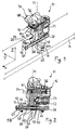
- a heel unit generally designated 10 in the drawings comprises a base 12 for attachment to a ski 14, a binding body 16, and a bearing assembly 18 by which the binding body 16 is movably supported relative to the base 12.
- a plurality of fastening holes 20 can pass through the base part, in order to enable fastening by means of screws 22.
- the heel unit 10 in particular the specifications for fixing the base part 12 and the binding body 16 define an X-direction along the running direction of the touring ski, referring to the running direction of the touring ski, a Y-direction which runs in the ski plane of the touring ski (horizontally) and oriented orthogonally to the X direction, and a Z direction, which is oriented orthogonal to the X direction and to the Y direction (vertical upward).
- X direction points forward in the direction of touring ski, in the present disclosure terms such as "top”, “bottom”, “side”, “front”, “behind”, “horizonta!, " vertical "or the like with reference to the above-defined coordinate system.
- the binding body 16 carries two coupling pins 24r, 241 (approximately parallel to one another in the X-direction).
- FIGS. 1 and 4 the front ends of which form shoe engaging portions 26 adapted to provide a coupling between the heel unit 10 and a touring ski boot 28 (FIGS. FIG. 6 ) are provided.
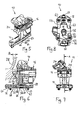
- the shoe engaging portions 26 project an amount a via a front abutment surface 30 of the binding body 16 so that they maximally extend into a rear recess 32 of the touring ski boot 28 penetrate a depth a until a rear abutment surface 34 of a heel portion of the sole of the touring ski boot 28 abuts against the front abutment surface 30 of the binding body 16 ( FIG. 6 ).
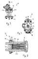
- the coupling pins 24r, 241 are substantially parallel to each other, wherein to provide a My-trigger mechanism in a conventional manner at least one of the two pins in the Y direction within certain limits against the force of a My release spring 36 (in Figures 2 and 9 shown in FIGS. 1 . 5 and 6 omitted) is movable.
- a trigger mechanism can be used, as in the AT 402 020 B is described, the disclosure of which is fully incorporated by reference into the present disclosure with respect to the movable support of the coupling pins and acting between the coupling pins spring assembly by reference.
- the coupling pins 24r, 241 may be pivotally mounted at their opposite the shoe engaging portions 26 ends about an axis extending in the Z direction.
- the compressive force acting in the X direction My release spring 36 is supported on the one hand on the binding body 16 and on the other hand is supported on a displaceable in the binding body 16 in the X direction spring bearing 40 from.
- the spring bearing 40 may have wedge surfaces 42 which slide on corresponding wedge surfaces 44 which are each firmly connected to the pins 24r, 24l. A movement of at least one of the pins 24r, 24l in the Y-direction in the sense of an increase in the distance between the pins 24r, 241 then leads to a sliding of the two wedge surfaces 42, 44 to each other, such that the spring bearing 40 against the force of the My- Release spring 36 is pushed back.
- the My-triggering mechanism of the heel unit 10 cooperates with a corresponding triggering contour (not shown) on the boundary of the recess 32 of the touring ski boot 28.
- the triggering contour is shaped such that the coupling pins 24r, 241 slide out along the recess 32 of the touring ski boot 28 can release the touring ski boot 28, but against the force of the My trip spring 36 are spread apart from each other.
- the My-triggering takes place only when exerting a predetermined torque on the ski boot about the Y-axis or upon action of a force on the heel portion of the touring ski boot 28 vertically upward, which is greater than one predetermined My trigger force.
- the heel unit 10 further includes an Mz triggering mechanism.
- the Mz-tripping is realized in that the binding body 16 and thus also the coupling pins 24r, 24l extending about a Z-direction axis M of an Mz-trigger bearing of the bearing assembly 18 is pivotally supported on the base member 12.
- the bearing assembly 18 may for this purpose comprise a bearing pin 46, on which the binding body 16 together with the coupling pins 24r, 24l is pivotable about the axis M.
- the mounting of the binding body 16 on the bearing pin 46 is biased in a down position, in which the shoe engaging portions 26 of the coupling pins 24r, 241 point in the X direction forward and can engage in the recess 32 of the touring ski boot 28.
- a known Mz-triggering mechanism may be provided which, for example, in the EP 0 199 098 A2 is described.
- a cam surface 48 may be provided, on which at a relative rotation between the binding body 16 and bearing pin 46, a cam follower 50 (in FIG. 2 shown in FIGS. 1 . 5 and 6 omitted), which is movably guided on the binding body 16 and by the force of an Mz release spring 52 (in FIG.
- the Mz release spring 52 can be supported on the one hand on a Vorrisonseinstellelement 54, which is mounted in an adjustable, but during normal operation fixed position on the binding body 16, and on the other hand supported on the cam follower 50.
- the Vorongseinstellelement 54 may be a screw, so that by adjusting the screw, the distance between the two support points of the Mz-release spring 52 and thus the bias of the Mz-release spring 52 is adjustable.
- the contour of the cam surface 48 is selected so that the binding body is biased to the descent position in which the shoe engaging portions 46 of the coupling pins 24r, 241 are substantially forward in the X direction. Further, the cam surface 48 is shaped so that upon rotational movement of the binding body 16, the cam follower 50 is urged toward compressing the Mz trip spring 52 so as to counteract the pivotal movement of the binding body 16 from the downhill position.
- this force exceeds a predetermined Mz release force, for example because a heel portion of the touring ski boot 28 in the lateral direction (Y direction) is pressed in the event of a fall and a twisting of the skis, the force of the Mz release spring 52 is overcome and the binding body turns along with the coupling pins 24r, 24l to the side away, so that the engagement of the touring ski boot is released.
- This movement is the Mz release movement of the binding body 16 or the coupling pins 24r, 241.
- the bearing arrangement 18, with which the binding body 16 is mounted on the base part 12, additionally comprises a suspension bearing, which allows a suspension movement of the binding body 16 and thus of the coupling pins 24r, 241.
- the bearing pin 46 is guided linearly displaceable in the X direction on the base part 12 and biased by the action of a spring element 56 in the forward direction (towards the ski boot 28).
- the linear guide can comprise a rail-like guide element 58 attached to the base part 12, which extends in a straight line in the X direction and on which the bearing pin 46 or the binding body 16 held thereon is guided.
- the guide element 58 is rod-shaped, in particular a screw extending in the X direction, wherein the guide element 58 passes through a suitable through hole 60 of the binding body (in particular the bearing journal 46) so that the binding body 16 moves in the X direction relative to the guide element 58 can.
- the binding body can be additionally secured by a second guide against tilting.
- the bearing pin 46 penetrates in the vertical direction a slot-shaped recess 62 of the base part 12 and has at its lower end a flange, widened foot portion 63 which engages under the base part 12, so that the foot portion 63 between the base part 12 and the surface of the Skis 14 is kept.
- the bearing pin 46 is thus stably guided linearly movable on the foot portion 63 and at the passage opening 60.
- Alternative means for guiding the linear movement of the trunnion 46 or the binding body 16 may be used, for example a guide along an inner boundary surface of the recess 62.
- the spring element 56 is preferably supported, on the one hand, on a first spring bearing 64, which is operatively connected to the base part 12, and on the other hand is supported on a spring bearing 66, which is operatively connected to the binding body 16 or formed thereon.
- the first spring bearing 64 may be formed in the manner of a nut and engage with the screw of the guide member 58.
- the guide element 58 penetrates in the exemplary embodiment in the X direction, the spring element 56 and is rotatably, but held axially immovably on a bearing 67 on the base part 12. The rotation of the guide member 58, for example, by operation of a screw head 68 with engagement portion for a screwdriver, leads to a shift of the first spring bearing 64 along the X direction.
- the second spring bearing 66 may be provided on the inside of a recess 59 which is provided as a downwardly open recess at the lower end of the bearing journal 46 and in which the spring element 56 is received. In this way, the spring element can be mechanically stable and well protected from external influences in a cavity between the bearing pin 46 and the surface of the ski 14 and the base part 12 are housed.
- the X-direction through opening 60 for the guide element 58 traverses the recess 59, so that in the bearing pin 46, the through opening 60 comprises at least two opposite passage opening sections 60a and 60b, so that the guide element 58 the bearing pin 46 at two spaced passage opening portions 60a, 60b of the through hole 60 reliably leads.
- the guide element 58 in the illustrated embodiment passes first through the first passage opening portion 60a axially displaceable without threaded engagement, then the first spring bearing 64 in threaded engagement, then the spring member 56 axially displaceable without threaded engagement, then the second passage opening portion 60b axially displaceable without thread engagement and is finally in stock 67 rotatably mounted and axially immovable.
- the first spring bearing 64 may further form a stop for limiting the movement of the binding body 16 along the guide member 58 in the direction of the biasing force of the spring means 56.
- this stop can be done by conditioning the first spring bearing 64 on a front suspension stop 69 of the binding body 16, which is formed on a second spring bearing 66 opposite inner wall of the recess 59.
- the position of the first spring bearing 64 in the X direction can be adjusted by turning the guide element 58.
- the first spring bearing 64 bears against the inner wall of the recess 59 and is held in this position by the force of the spring means 56.
- the displacement of the first spring bearing 64 in the X direction by adjusting movement of the guide element 58 thus entails a corresponding displacement of the binding body 16 in the X direction.
- the adjustment movement of the guide element 58 accordingly enables an adjustment of the position of the binding body 16 in the X direction to adapt the binding to the length of the shoe.
- the maximum spring travel is preferably smaller than the length a, with which the shoe coupling portions 26 of the coupling pins 24r, 24l protrude beyond the front abutment surface 30 of the binding body 16 in the X direction. This ensures that the suspension movement of the binding body in the X direction can not lead to the coupling pins 24r, 241 sliding out of engagement with the touring ski boot 28.
- the heel unit 10 is a climbing aid arrangement 74 which supports the heel portion of the touring ski boot 28 in a walking position of the heel unit 10 at a predetermined height above the surface of the ski 14.
- the climbing aid assembly 74 comprises a first climbing aid 76 which is pivotally mounted on the binding body 16 so that it is pivotable between a passive position in which they can not engage the touring ski boot 28, and an active position in which they over projects the binding body 16 so that the touring shoe pivotally mounted on the toe 28, which moves down from above to the ski 14, settles on the first climbing aid 76 and thus can be supported at a first height above the ski 14.
- the climbing aid assembly 74 may further include a second climbing aid 78, which is also mounted for pivotal movement between a passive position and an active position on the binding body 16, wherein a second height in which the heel portion of the touring ski boot 28 is supported by the second climbing aid 78 is greater as the first height of the first climbing aid 76.
- the first climbing aid 76 and the second climbing aid 78 may be held on a common axis of rotation on the binding body 16.
- the active position of the second, higher climbing aid 78 can be defined by the fact that the second climbing aid 78 settles in the active position on the first climbing aid 76 pivoted into the active position.
- the first climbing aid 76 is then first to put into the active position in which it can rest on the binding body 16, whereupon the second climbing aid 78 is pivoted to the active position until they are on the first climbing aid 76th settles.
- the touring ski boot 28 can be supported in the walking position in three different heights above the ski 14: In flat terrain, both can Climbing aids 76, 78 are pivoted into the passive position, so that the touring ski boot 28 can be pivoted down to the surface of the ski 14; at medium slope, the first climbing aid 76 can be pivoted into the active position, so that the touring ski boot 28 can be supported in the first height above the ski 14; and in the case of a steep slope, the second climbing aid 78 can also be pivoted into the active position, so that the touring ski boot 28 can be supported at the second height above the ski 14.
- the binding body 16 can be rotated by 90 ° clockwise, so that the coupling pins 24r, 24l point approximately in the Y direction.
- the touring ski boot 28 which is pivotally mounted in its front portion on a front unit of the touring ski binding about a pivot axis extending transversely to the X direction, can then lift freely from the heel unit 10. When lowering the touring ski boot 28 comes this depending on the setting of the climbing aid then either on the second climbing aid 78, on the first climbing aid 76 or on the ski 14 and the base part 12 to rest.
- the heel unit 10 In the down position, the heel unit 10 is rotated relative to the rotation of the binding body 16 about the axis M to the position shown in the figures and is biased by the Mz release spring 52, the cam surface 48 and the cam follower 50 in this position.
- the coupling pins 24r, 241 point forwards in the X direction and engage in the recess 32 of the touring ski boot 28.
- a rear abutment surface 34 of the touring ski boot 28 (rear edge of a sole portion of the shoe) abuts against the front abutment surface 30 of the binding body 16, so that the coupling pins 24r, 241 with their entire projecting length a in the Recess 32 are introduced.
- the mounting position of the heel unit 10 on the ski 14 and / or the adjustment of the guide member 58 is tuned to the size of the touring ski boot 28 that in the downhill position, in which the touring ski boot 28 is held by both the front unit and the heel unit 10, the front spring stop 69 of the binding body 16 is held at a distance from the first spring bearing 64, the spring element 56 is not completely compressed. If there is a deflection of the ski 14 when driving through a floor depression, in which the ski tip and the ski end are raised and a portion of the ski 14 is lowered below the touring ski boot 28, then the distance between the base part 12 and the front unit of the touring ski binding decreases.
- the touring ski boot 28 Since the touring ski boot 28 is not compressible to the same extent and rests with its rear abutment surface 34 on the front abutment surface 30 of the binding body 16, the touring ski boot 28 moves the binding body 16 together with the coupling pins 24r, 241 and the bearing pin 46 relative to the base part 12 and against the bias of the spring element 56 in the X direction to the rear.
- the heel unit 10 can thus compensate for the change in distance between the fastening points of the front unit and the heel unit 10, so that the heel unit 10, the front unit and the fastening means between the base part 12 and ski 14 are not exposed to excessive loads, resulting in damage to the heel unit 10 or the Front unit could lead.
- the ski When driving over a ground elevation, the ski may deflect in the sense that the ski tip and the ski end are lowered while a portion of the ski 14 undulates below the touring ski boot 28. In this case, the distance between the base part 12 and the front unit of the binding increases.
- the slidable mounting of the binding body 16 according to the invention and the bias of the binding body 16 in the forward direction through the Spring element 56 then prevents the rear abutment surface 34 of the touring ski boot 28 from lifting off the front abutment surface 30 of the binding body 16. Instead, the spring element 56 holds the binding body 16 in contact with the touring ski boot 28 and prevents the coupling pins 24r, 241 from sliding out of the recess 32.
- the binding body 16 moves over bumps relative to the base member 12 and is held in abutting contact with the heel portion of the touring ski boot 28 by the spring member 56. Regardless of the Ski pleagung a secure engagement between the coupling pins 24r, 241 is ensured in this way and a friction and wear-intensive relative movement between the coupling pins 24r, 241 and the recess 32 during departure is prevented.
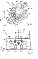
- a heel unit 110 of the second exemplary embodiment of the present invention comprises a base part 112 to be fastened to a ski 111, a binding body 114 held on the base part 112, and coupling projections 116 held on the binding body 114 for engagement with a heel section 210 (FIG. FIG. 11 ) of a touring boot 200.
- Attachment means for fixing the base part 112 to the ski 111 define a skid E of a ski 111 connected to the heel unit (horizontal plane in this disclosure) and a ski longitudinal axis M along a central axis of the ski.
- the ski longitudinal axis M runs in an X-direction of a coordinate system of the heel unit.
- a skin normal, which is perpendicular to the plane E, runs in a Z direction of the coordinate system, and a Y direction of the coordinate system is orthogonal to the X direction and orthogonal to the Z direction.
- the binding body 114 may be pivotally supported on a bearing assembly 118 about an axis extending in the Z direction with respect to the base member 112.
- the bearing arrangement 118 may comprise a bearing journal 120, which is inserted into an associated recess 122 of the binding body 114.
- the mounting of the binding body 114 on the trunnion 120 is preferably biased to a descent position in which the coupling protrusions 116 point forward in the X direction.
- the Mz-triggering mechanism already described for the first embodiment may be provided.
- the bearing assembly 118 with which the binding body 114 is mounted on the base part 112, additionally comprises a suspension bearing, which allows a suspension movement of the binding body 114 and thus of the coupling projections 116.
- the bearing pin 120 is linearly displaceable in the X direction on the base part 112 and biased by the action of a spring element 132 in the forward direction (toward the ski boot 200).
- the linear guide may comprise a first rail portion 134 formed on the base portion 112 and a second rail portion 138 formed on a carriage 136 and slidingly engaged with the first rail portion 134.
- the journal 120 may then be connected to the carriage 136 and slidable along the X direction on the base part 112.
- By the spring element 132 of the carriage 136 is biased forward in the X direction. Its direction of movement in the X-direction forward is limited by a first stop 140, which is operationally held (ie during normal operation, eg during departure) stationary with respect to the base part 112.
- a second stop 142 At the first stop 140 of the carriage 136 abuts with a second stop 142, when acting on the binding body 114 no force in the X direction (eg with decoupled touring boot).
- the spring element 132 is housed in a recess 144 of the carriage 136 which is opened towards the ski and supports with its front end against a front boundary wall 146 of the recess 144, while the rear end of the spring element 132 bears against a spring bearing 148 which is operative is held stationary to the base part 112.
- the spring bearing 148 also forms the first stop 140, so that the spring bearing 148 has a double function for supporting the spring element 132 and for limiting the movement of the carriage 136.
- the spring bearing 148 may be adjustable in position relative to the base member 112 to adjust the unloaded position of the carriage 136 along the X direction.
- the spring bearing 148 may be provided as a threaded nut, which is penetrated by a thread extending in the X direction screw 150 in the threaded engagement.
- the screw 150 may be mounted at its end remote from the spring bearing 148 at a bearing portion 152 of the base member 112 so that the screw 150 can rotate about its longitudinal axis, but can not move in the X direction. To adjust the screw 150, this may have a screw head 154 with a tool engagement portion.
- the spring element 132 is preferably designed as a helical spring, such that the spring bearing 148 passing through screw 150 can penetrate smoothly into the interior of the coil spring.
- the My triggering mechanism includes the coupling protrusions 116 which are movably supported on the binding body 114.
- the coupling projections 116 are preferably formed at front ends of two coupling pins 156, which are pivotable on pin bearing sections 160 at holding sections 158 facing away from the coupling projections 116 are stored the binding body.
- the pin bearing portions 160 support the coupling pins 156 so that the coupling projections 116 are movable at least in a direction of movement away from the skiebene.
- the cam portions 162 of the two coupling pins 156 are preferably in contact with a common transmission member 164 which is movably supported on the binding body 114 so that movement of the pins 156 via the cam portions 162 is translated into movement of the transmission member 164.
- the transmission part 164 can be pivoted to the binding body 114 with a pivot axis 166 extending in the Y direction.
- the transmission part 164 further comprises a spring bearing 168, in particular a spaced apart from the pivot axis 166 spring bearing 168 for supporting a My-release spring 170.
- the contact between the Mit Spotifyabitesen 162 and the transmission part 164 may lie in a between the spring bearing 168 and the pivot axis 166 Section of the transmission part 164 to improve the power transmission between the transmission part 164 and My release spring 170 by the leverage of the transmission part 164.
- the cam portions 162 slide on first guide surfaces 172 of the transmission part 164 which are substantially parallel to the axes of the coupling pins 156 on either side of the cam portions 162 and force the cam portions 162 on trajectories along the directions of movement r 1 and r 2 .
- the directions of movement r 1 and r 2 of the driving portions 162 extend obliquely away from the scissors E and obliquely to the Z direction (skin normal).
- the directions of movement r 1 and r 2 are V-shaped and symmetrical to a vertical longitudinal center plane V, which is orthogonal to the axis E in the X direction and the ski in the longitudinal direction halved.
- the directions of movement r 1 and r 2 may each include an angle of between about 10 degrees and about 45 degrees, more preferably an angle between about 15 degrees and about 30 degrees.
- the transmission part 164 can also be a normal position stop 174 and / or a release stop 176 be formed for the Mit Spotifyabête 162 to limit the pivoting range of the coupling pins 156 in at least one of the two positions, normal position and release position.
- the first guide surfaces 172, the normal position stop 174 and the release stop 176 can be provided together as inner boundary walls of a common recess.
- the coupling between the driver sections 162 and the transmission part 164 can then be described in each case as a slot coupling, in which the transmission part 164 has two substantially V-shaped elongated holes in which the driver sections 162 are guided along the directions of movement r 1 and r 2 and with respect their movement end positions are limited.
- the transmission part 164 preferably has second guide surfaces 178 for each of the driver sections 162 of the coupling pins 156, against which rear sides 180 of the driver sections 162 abut.
- the second guide surfaces 178 are designed so that when, during a pivoting movement of the coupling pins 156 along the directions of movement r 1 and r 2, the driver portions 162 slide on the second guide surfaces 178, the transmission member 164 is pivoted about the pivot point 166. This can be realized by an obliquely to the axis of the coupling pins 156 extending guide surface 178 and a trough-shaped guide surface 178.
- the second guide surfaces 178 structurally simple with the first
- Guide surfaces 172 are connected by the second guide surfaces 178 are formed as the bottom of a recess whose side walls are formed by the first guide surfaces 172 (and optionally by the stops 174, 176). At the bottom 178 of the recess then a slot is provided whose dimensions are smaller than the dimensions of the recess and through which a narrower portion of the coupling pins 156, but not the driver portions 162, are passed.
- a front end of a My release spring 170 may be supported on a spring bearing 168 of the transmission part 164.
- a bearing pin 182 attached to the front end of the My release spring 170 is mounted on the spring bearing 168 of the transmission part 164 via a ball-and-socket coupling 184.
- the ball-and-socket coupling 184 provides for the translation of the pivotal movement of the spring bearing 168 of the transmission member 164 into a substantially linear compression movement of the My trip spring 170 such that the My trip spring 170 is actuated only along its rectilinear compression or decompression direction.
- the My trip spring 170 is oriented substantially in the X direction. At the trailing end, the My trip spring 170 may be coupled directly to a binding body-fixed portion, or as illustrated in the embodiment, to provide the possibility of adjusting the biasing force of the My trip spring 170 and thus adjusting the My trip force with a My Release force adjustment mechanism 186 may be provided.
- the My release force adjustment mechanism 186 may include a second journal 188 which is attached to a rear end of the My release spring 170 and whose distance from a binding body-fixed bearing portion 190 is adjustable by adjusting a threaded screw 192.
- the threaded screw 192 may be rotatably mounted on the bearing portion 190, but immobile in the axial direction of the My release spring 70 and with an internal thread of the second journal 188 into engagement, so that by rotation of the threaded screw 192, in particular by actuation via a tool engagement portion 194 at the end of the threaded screw 192, the second bearing pin 188 can be moved in the axial direction of the My-release spring 170. In this way, the bias of the trigger spring 170 can be adjusted to influence the My-triggering behavior of the heel unit 110.
- the heel unit 110 of the second embodiment may further include a first climbing aid 196 and a second climbing aid 198 pivotally attached to the heel unit 110 for selectively being pivoted individually or jointly into an area between the ski and the toe shoe (active position), so that the touring shoe 200 can be supported at a corresponding height above the ski. In a conventional manner, walking on a slope is facilitated in this way.
- both climbing aids 196, 198 are mounted on a common pivot axis which extends in the Y direction. A special space and component savings can also be achieved if on the common pivot axis 166 of the climbing aids 196, 198 and the transmission part 164 is pivotally mounted on the binding body 114.
- a shoe control section 206 is arranged, which has an obliquely to the skiebene E extending, to the rear end of the ski rising toward control contour 208.
- a lower end 208u of the control contour 208 terminates with respect to the X direction approximately at the level of the front ends of the coupling protrusions 116, or projects forward even beyond the front ends of the coupling protrusions 116.
- An upper end 208o of the control contour 208 lies in the X direction behind the front ends of the coupling projections 116.
- the control contour 208 preferably includes an angle of between about 45 and about 75 degrees with the scissors E to ensure safe sliding of the heel portion of the touring boot one at a time To ensure sufficient displacement of the binding body 116 in the X direction.
- the operation of the heel unit 110 of the second embodiment of the invention will be explained.
- the first stop 140 of the spring bearing 148 abuts against the second stop 142 of the carriage 136
- the coupling pins 156 are in their normal position, in which the coupling projections 116 occupy their lowest and approximate position, in particular the Mit Spotifyabête 162 abut the normal position stops 174.
- the touring shoe 200 is decoupled from the heel unit 110.
- the touring binding is in a walking position .
- the first climbing aid 196 is folded down until it rests on the top of the ski 111 or on top of the base 112, as in FIG FIG. 16 is illustrated.
- a first shoe pad 202 of the first climbing aid 196 is then disposed at a first climbing height above the skid E (approximately at the level of the coupling projections 116 or above) to support the heel portion 210 of the toe boot 200 at that height.
- the second climbing aid 198 With a rise with greater slope and the second climbing aid 198 can be folded down until it is supported on the first climbing aid 196 and a second shoe pad 204 of the second climbing aid 198, the heel section 210 of the touring boot 200 in a second, greater climbing height on the screed E is supported.
- the touring binding must be adjusted from the walking position to the downhill position.
- the optionally folded down first or second climbing aids 196, 198 are folded upwards, so that the shoe control section 206 is in the pivoting region of the heel section 210 of the touring boot 200.
- the heel unit 110 is now in the entry position. If the heel portion 210 is lowered and strikes the control contour 208, the heel portion 210 slides on the control contour 208, thereby displacing the shoe control portion 206 to the rear. Since the shoe control portion 206 abuts with its rear side 209 on the transmission part 164, the movement of the shoe control portion 206 in the X direction is transmitted to the rear on the transmission part 164.
- the My release spring 170 has a higher spring constant or a higher bias than the spring element 132 of the suspension bearing, on which the binding body 114 is held relative to the base member 112 in the X direction displaceable.
- the backward displacement of the shoe control section 206 effected by the toe shoe 200 thus does not lead to a pivotal movement of the transmission part 164 but rather displaces the binding body 114 in compression in the backward direction of the spring element 132.
- the binding body 114 is displaced in the rearward direction such that the front ends of the coupling projections 116 are located in the same direction with the heel portion 210 or behind the heel portion 210 in the X direction are.
- the heel portion 210 may thus continue to slide downwardly on the lower end 208u of the control contour 208 until detent portions 230 of recesses 222 on the heel portion 210 of the toe shoe 200 are sufficiently aligned with the coupling projections 116.
- the driver can get into the downhill position of the touring binding by the touring unit 200, which is pivotally held on the front unit of the touring binding, is pushed towards the ski by a simple movement until the coupling projections 116 engage in the recesses 222 of the touring boot 200.
- the force sufficient for this is dependent on the spring force of the spring element 132 and thus is in particular independent of the spring force of the My-trigger spring 170. In this way it can be achieved that even when using a My-release spring 170 with very high clamping force to enable a particularly Sporty driving a relatively easy entry into the touring binding is possible because the pressure required for the entry force can be defined independently of the My-release spring 170 by the spring element 132.
- Analogous to the first embodiment takes over during departure, the longitudinally displaceable mounting of the binding body 114 under the action of the spring member 132, the task of dynamically balancing a Ski bebiegung when driving through bumps, so that during departure of the binding body 114 always in safe engagement and in close contact with the heel section of the touring boot can be kept.
- the heel unit 110 triggers. If the momentary impact force acting on the heel portion 210 in the direction of an arrow A is greater than the My release force of the My release mechanism of the heel unit 110, which depends, inter alia, on the force of the My release spring 170, then begins the Heel section 210 of the touring boot 200 to lift off the ski in the direction of arrow A.
- the coupling projections 116 are engaged with the locking portions 230 of the recesses 222 of the heel portion 210, the coupling projections 116 are also lifted upwardly away from the scissors E by a force acting in the direction of the arrow A.
- the upward movement of the coupling projections 116 forces, via the guidance of the driver sections 162 on the transmission part 164, a V-shaped upward movement of both coupling projections 116, such that the distance between the two coupling projections 116 increases from the second axis and the distance between the two coupling projections 116 increases.
- the Coupling pins 156 pivoted so far that the coupling protrusions 116 finally slide out of the locking portions 230 on the heel portion 210 of the toe shoe 200, so that the coupling projections 116 can emerge from opening portions 224 of the touring shoe 200 to the sole 226 out of the recesses 222 and the touring shoe 200 thus from the Heel unit 110 is decoupled. In this way, a reliable fall triggering of the heel unit 110 is ensured.
Landscapes
- Footwear And Its Accessory, Manufacturing Method And Apparatuses (AREA)
Priority Applications (1)
| Application Number | Priority Date | Filing Date | Title |
|---|---|---|---|
| EP13178488.6A EP2659939B1 (fr) | 2011-07-14 | 2011-09-13 | Unité de talon pour une fixation de ski de randonnée |
Applications Claiming Priority (1)
| Application Number | Priority Date | Filing Date | Title |
|---|---|---|---|
| DE201110079210 DE102011079210A1 (de) | 2011-07-14 | 2011-07-14 | Ferseneinheit für eine Tourenskibindung |
Related Child Applications (2)
| Application Number | Title | Priority Date | Filing Date |
|---|---|---|---|
| EP13178488.6A Division EP2659939B1 (fr) | 2011-07-14 | 2011-09-13 | Unité de talon pour une fixation de ski de randonnée |
| EP13178488.6A Division-Into EP2659939B1 (fr) | 2011-07-14 | 2011-09-13 | Unité de talon pour une fixation de ski de randonnée |
Publications (3)
| Publication Number | Publication Date |
|---|---|
| EP2545966A2 true EP2545966A2 (fr) | 2013-01-16 |
| EP2545966A3 EP2545966A3 (fr) | 2013-03-27 |
| EP2545966B1 EP2545966B1 (fr) | 2014-08-06 |
Family
ID=44677710
Family Applications (2)
| Application Number | Title | Priority Date | Filing Date |
|---|---|---|---|
| EP20110181098 Active EP2545966B1 (fr) | 2011-07-14 | 2011-09-13 | Talonnière pour une fixation de ski de randonnée |
| EP13178488.6A Active EP2659939B1 (fr) | 2011-07-14 | 2011-09-13 | Unité de talon pour une fixation de ski de randonnée |
Family Applications After (1)
| Application Number | Title | Priority Date | Filing Date |
|---|---|---|---|
| EP13178488.6A Active EP2659939B1 (fr) | 2011-07-14 | 2011-09-13 | Unité de talon pour une fixation de ski de randonnée |
Country Status (2)
| Country | Link |
|---|---|
| EP (2) | EP2545966B1 (fr) |
| DE (1) | DE102011079210A1 (fr) |
Cited By (11)
| Publication number | Priority date | Publication date | Assignee | Title |
|---|---|---|---|---|
| EP2570160B1 (fr) * | 2011-09-13 | 2015-04-01 | Salewa Sportgeräte GmbH | Unité de talon pour une fixation de ski de randonée |
| DE102013224576A1 (de) | 2013-11-29 | 2015-06-03 | Salewa Sport Ag | Gleitbrettbindung mit Drehlager |
| DE102013224571A1 (de) | 2013-11-29 | 2015-06-03 | Salewa Sport Ag | Ferseneinheit mit Bremsanordnung |
| DE102013224574A1 (de) | 2013-11-29 | 2015-06-03 | Salewa Sport Ag | Ferseneinheit für eine Tourenbindung und Tourenbindung |
| US9242167B2 (en) | 2013-07-09 | 2016-01-26 | G3 Genuine Guide Gear Inc. | Ski binding heel unit |
| DE102015210373A1 (de) | 2015-06-05 | 2016-12-08 | Salewa Sport Ag | Kopplungselement zur Befestigung an einem Sportschuh |
| EP3120903A1 (fr) * | 2016-10-14 | 2017-01-25 | Fritschi AG - Swiss Bindings | Talonnière |
| DE102020203271A1 (de) | 2020-03-13 | 2021-09-16 | Salewa Sport Ag | Ferseneinheit mit auslöse- und verstellmechanismus |
| DE102022106276A1 (de) | 2022-03-17 | 2023-09-21 | Salewa Sport Ag | Ferseneinheit für eine Gleitbrettbindung mit Mz-Auslösung über Nockenkörper |
| EP4272845A3 (fr) * | 2022-05-02 | 2023-12-06 | MARKER Deutschland GmbH | Talonnière avec guidage rectiligne des éléments de retenue pour une libération verticale |
| US20240325864A1 (en) * | 2023-04-01 | 2024-10-03 | Cameron Allan Shute | Ski Binding Heel Unit |
Families Citing this family (8)
| Publication number | Priority date | Publication date | Assignee | Title |
|---|---|---|---|---|
| DE102012214001B4 (de) | 2012-08-07 | 2014-03-13 | Marker Deutschland Gmbh | Skibremse mit Verriegelung |
| DE102013221778A1 (de) * | 2013-10-25 | 2015-04-30 | Salewa Sport Ag | Ferseneinheit für eine Tourenbindung |
| FR3026311A1 (fr) * | 2014-09-26 | 2016-04-01 | Salomon Sas | Talonniere de fixation d'une chaussure sur une planche de glisse |
| DE102022106275A1 (de) | 2021-09-13 | 2023-03-16 | Salewa Sport Ag | Ferseneinheit für eine Gleitbrettbindung mit Verstärkungsplatte |
| DE102021131143A1 (de) | 2021-11-26 | 2023-06-01 | Salewa Sport Ag | Ferseneinheit einer Tourenbindung, umfassend eine einstückige Steighilfe mit mehreren Abstützmöglichkeiten |
| EP4245386B1 (fr) | 2022-03-17 | 2025-07-30 | Salewa Sport AG | Talonniere pour fixation de planche de glisse avec plaque de renfort |
| DE102022110764A1 (de) * | 2022-05-02 | 2023-11-02 | Marker Deutschland Gmbh | Fersenhalter mit einstellbarer Kraft für Vertikalauslösung |
| DE102024129167A1 (de) * | 2024-10-09 | 2026-04-09 | Salewa Sport Ag | Ferseneinheit für eine Tourenbindung |
Citations (3)
| Publication number | Priority date | Publication date | Assignee | Title |
|---|---|---|---|---|
| EP0199098A2 (fr) | 1985-03-25 | 1986-10-29 | Fritz Dipl.-Ing. Barthel | Fixation pour ski de randonnée |
| AT402020B (de) | 1993-08-19 | 1997-01-27 | Barthel Fritz | Fersenbacken für eine skibindung |
| WO2012024809A1 (fr) | 2010-08-27 | 2012-03-01 | Fritschi Ag - Swiss Bindings | Fixation de ski de randonnée à talonnière comportant une zone de glissement dynamique |
Family Cites Families (10)
| Publication number | Priority date | Publication date | Assignee | Title |
|---|---|---|---|---|
| DE7805344U1 (de) * | 1978-02-22 | 1978-06-08 | Vereinigte Baubeschlagfabriken Gretsch & Co Gmbh, 7250 Leonberg | Fersenbildung mit einem auf einer Grundplatte verschiebbar angeordneten Grundkörper |
| US3241849A (en) * | 1964-10-05 | 1966-03-22 | Great Lakes Inst | Safety release ski bindings |
| US3716248A (en) * | 1970-07-29 | 1973-02-13 | P Wiley | Tension adjustable releasable ski binding and method |
| DE3153702C2 (de) * | 1981-03-13 | 1995-09-21 | Rohrmoser Alois Skifabrik | Skibindung |
| US5213357A (en) * | 1991-05-23 | 1993-05-25 | Nordica S.P.A. | Ski binding with elastic recovery means for free ski flexing |
| FR2873590B1 (fr) * | 2004-07-30 | 2006-12-01 | Salomon Sa | Ensemble de retenue d'une chaussure sur une planche de glisse, notamment un ski alpin |
| DE102006043493A1 (de) * | 2006-09-12 | 2008-03-27 | Marker Deutschland Gmbh | Fersenseitiges Schuhhalteraggregat einer Skibindung |
| WO2009105866A1 (fr) * | 2008-02-29 | 2009-09-03 | G3 Genuine Guide Gear Inc. | Unité talon pour fixation de randonnée en montagne |
| DE102009043802A1 (de) * | 2009-09-30 | 2011-03-31 | Marker Deutschland Gmbh | Skibindung mit Gerippestruktur |
| DE102010006218A1 (de) * | 2010-01-29 | 2011-08-04 | MARKER Deutschland GmbH, 82377 | Skibindung mit Steighilfe |
-
2011
- 2011-07-14 DE DE201110079210 patent/DE102011079210A1/de not_active Ceased
- 2011-09-13 EP EP20110181098 patent/EP2545966B1/fr active Active
- 2011-09-13 EP EP13178488.6A patent/EP2659939B1/fr active Active
Patent Citations (3)
| Publication number | Priority date | Publication date | Assignee | Title |
|---|---|---|---|---|
| EP0199098A2 (fr) | 1985-03-25 | 1986-10-29 | Fritz Dipl.-Ing. Barthel | Fixation pour ski de randonnée |
| AT402020B (de) | 1993-08-19 | 1997-01-27 | Barthel Fritz | Fersenbacken für eine skibindung |
| WO2012024809A1 (fr) | 2010-08-27 | 2012-03-01 | Fritschi Ag - Swiss Bindings | Fixation de ski de randonnée à talonnière comportant une zone de glissement dynamique |
Non-Patent Citations (2)
| Title |
|---|
| "ALPINE TOURING BINDINGS", TELEMARK-PYRENEES.COM, 13 April 2004 (2004-04-13), pages 1 - 3, XP003033168, Retrieved from the Internet <URL:HTTP://WEB.ARCHIVE.ORG/WEB/20040413184134/HTTP://WWW.TELEMARK-PYRENEES.COM/BINDINGS%20-%20AT.HTM> [retrieved on 20120615] |
| "RENTAL PLATE TOURLITE TECH - DYNAFIT", TELEMARK-PYRENEES.COM, 10 August 2004 (2004-08-10), pages 1, XP003033169, Retrieved from the Internet <URL:HTTP://WEB.ARCHIVE.ORG/WEB/20040810174652/HTTP://WWW.TELEMARK-PYRENEES.COM/DYNAFIT-TOUR-TECH-RENTAL-PLATE.HTM> [retrieved on 20120517] |
Cited By (21)
| Publication number | Priority date | Publication date | Assignee | Title |
|---|---|---|---|---|
| EP2570160B1 (fr) * | 2011-09-13 | 2015-04-01 | Salewa Sportgeräte GmbH | Unité de talon pour une fixation de ski de randonée |
| US9242167B2 (en) | 2013-07-09 | 2016-01-26 | G3 Genuine Guide Gear Inc. | Ski binding heel unit |
| AT514518A3 (de) * | 2013-07-09 | 2018-02-15 | G3 Genuine Guide Gear Inc | Skibindungsferseneinheit |
| AT514518B1 (de) * | 2013-07-09 | 2018-05-15 | G3 Genuine Guide Gear Inc | Skibindungsferseneinheit |
| AT515186B1 (de) * | 2013-11-29 | 2020-04-15 | Salewa Sport Ag | Gleitbrettbindung mit Drehlager |
| DE102013224576A1 (de) | 2013-11-29 | 2015-06-03 | Salewa Sport Ag | Gleitbrettbindung mit Drehlager |
| DE102013224571A1 (de) | 2013-11-29 | 2015-06-03 | Salewa Sport Ag | Ferseneinheit mit Bremsanordnung |
| DE102013224574A1 (de) | 2013-11-29 | 2015-06-03 | Salewa Sport Ag | Ferseneinheit für eine Tourenbindung und Tourenbindung |
| DE102013224574B4 (de) | 2013-11-29 | 2022-03-31 | Salewa Sport Ag | Ferseneinheit für eine Tourenbindung und Tourenbindung |
| DE102013224576B4 (de) | 2013-11-29 | 2019-03-28 | Salewa Sport Ag | Gleitbrettbindung mit Drehlager |
| AT515186A3 (de) * | 2013-11-29 | 2020-01-15 | Salewa Sport Ag | Gleitbrettbindung mit Drehlager |
| DE102015210373A1 (de) | 2015-06-05 | 2016-12-08 | Salewa Sport Ag | Kopplungselement zur Befestigung an einem Sportschuh |
| EP3120903A1 (fr) * | 2016-10-14 | 2017-01-25 | Fritschi AG - Swiss Bindings | Talonnière |
| DE102020203271A1 (de) | 2020-03-13 | 2021-09-16 | Salewa Sport Ag | Ferseneinheit mit auslöse- und verstellmechanismus |
| EP3885010A1 (fr) | 2020-03-13 | 2021-09-29 | Salewa Sport AG | Talonniere de ski de randonnée pourvue de mécanisme de déclenchement et d'une possibilité de réglage sans efforts |
| US11369858B2 (en) * | 2020-03-13 | 2022-06-28 | Salewa Sport Ag | Heel unit comprising a release and adjustment mechanism |
| DE102022106276A1 (de) | 2022-03-17 | 2023-09-21 | Salewa Sport Ag | Ferseneinheit für eine Gleitbrettbindung mit Mz-Auslösung über Nockenkörper |
| EP4257212A2 (fr) | 2022-03-17 | 2023-10-11 | Salewa Sport AG | Unité de talon pour une fixation de planche de glisse dotée d'un déclenchement mz par l'intermédiaire d'une came |
| US12246246B2 (en) | 2022-03-17 | 2025-03-11 | Salewa Sport Ag | Heel unit for a gliding board binding having Mz release via a cam body |
| EP4272845A3 (fr) * | 2022-05-02 | 2023-12-06 | MARKER Deutschland GmbH | Talonnière avec guidage rectiligne des éléments de retenue pour une libération verticale |
| US20240325864A1 (en) * | 2023-04-01 | 2024-10-03 | Cameron Allan Shute | Ski Binding Heel Unit |
Also Published As
| Publication number | Publication date |
|---|---|
| DE102011079210A1 (de) | 2013-01-17 |
| EP2659939B1 (fr) | 2016-07-06 |
| EP2545966B1 (fr) | 2014-08-06 |
| EP2659939A1 (fr) | 2013-11-06 |
| EP2545966A3 (fr) | 2013-03-27 |
Similar Documents
| Publication | Publication Date | Title |
|---|---|---|
| EP2545966B1 (fr) | Talonnière pour une fixation de ski de randonnée | |
| EP2608853B1 (fr) | Butée arrière de randonnee avec plage de glissement dynamique | |
| EP2570160B1 (fr) | Unité de talon pour une fixation de ski de randonée | |
| DE102012201816B4 (de) | Vordereinheit für eine Gleitbrettbindung mit ersten und zweiten Eingriffsmitteln | |
| EP2666525B1 (fr) | Talonnière avec cale de montée et ensemble stop-ski | |
| EP2626117B1 (fr) | Unité avant pour la fixation d'une planche de glisse, fixation de ski de fond et fixation de saut à ski | |
| EP2431080B1 (fr) | Fixation de planche de glisse, notamment fixation de ski de randonnée | |
| EP3702005A1 (fr) | Talonnière | |
| EP3120903B1 (fr) | Talonnière | |
| EP2813268A1 (fr) | Automate avant | |
| EP3195906B1 (fr) | Talonniere ayant une configuration de marche | |
| DE3120090A1 (de) | Sicherheitsskibindung | |
| AT515189B1 (de) | Ferseneinheit für eine Tourenbindung und Tourenbindung | |
| EP3345659A1 (fr) | Talonnière automatique pour une fixation de ski | |
| CH706664B1 (de) | Skibindung. | |
| EP2865427B1 (fr) | Unité de talon pour une fixation de ski de randonée | |
| EP3015141B1 (fr) | Talonniere pour une fixation de planche de glisse dotee d'un systeme de frein | |
| EP3906980B1 (fr) | Talonnière pour une fixation de ski | |
| EP3848099B1 (fr) | Talon pourvu de cale de montée pour une fixation de randonnée | |
| EP0947225B1 (fr) | Fixation de sécurité de ski | |
| WO2025132937A1 (fr) | Unité de placement de talon pour une fixation de planche de glisse et planche de glisse | |
| DE102013220722A1 (de) | Gleitbrettbindung |
Legal Events
| Date | Code | Title | Description |
|---|---|---|---|
| PUAI | Public reference made under article 153(3) epc to a published international application that has entered the european phase |
Free format text: ORIGINAL CODE: 0009012 |
|
| AK | Designated contracting states |
Kind code of ref document: A2 Designated state(s): AL AT BE BG CH CY CZ DE DK EE ES FI FR GB GR HR HU IE IS IT LI LT LU LV MC MK MT NL NO PL PT RO RS SE SI SK SM TR |
|
| AX | Request for extension of the european patent |
Extension state: BA ME |
|
| PUAL | Search report despatched |
Free format text: ORIGINAL CODE: 0009013 |
|
| AK | Designated contracting states |
Kind code of ref document: A3 Designated state(s): AL AT BE BG CH CY CZ DE DK EE ES FI FR GB GR HR HU IE IS IT LI LT LU LV MC MK MT NL NO PL PT RO RS SE SI SK SM TR |
|
| AX | Request for extension of the european patent |
Extension state: BA ME |
|
| RIC1 | Information provided on ipc code assigned before grant |
Ipc: A63C 9/084 20120101ALI20130218BHEP Ipc: A63C 9/086 20120101ALI20130218BHEP Ipc: A63C 9/08 20120101ALI20130218BHEP Ipc: A63C 9/00 20120101AFI20130218BHEP |
|
| TPAC | Observations filed by third parties |
Free format text: ORIGINAL CODE: EPIDOSNTIPA |
|
| 17P | Request for examination filed |
Effective date: 20130927 |
|
| RBV | Designated contracting states (corrected) |
Designated state(s): AL AT BE BG CH CY CZ DE DK EE ES FI FR GB GR HR HU IE IS IT LI LT LU LV MC MK MT NL NO PL PT RO RS SE SI SK SM TR |
|
| TPAC | Observations filed by third parties |
Free format text: ORIGINAL CODE: EPIDOSNTIPA |
|
| RIC1 | Information provided on ipc code assigned before grant |
Ipc: A63C 9/08 20120101ALI20131219BHEP Ipc: A63C 9/084 20120101ALI20131219BHEP Ipc: A63C 9/086 20120101ALI20131219BHEP Ipc: A63C 9/00 20120101AFI20131219BHEP |
|
| GRAP | Despatch of communication of intention to grant a patent |
Free format text: ORIGINAL CODE: EPIDOSNIGR1 |
|
| INTG | Intention to grant announced |
Effective date: 20140307 |
|
| GRAS | Grant fee paid |
Free format text: ORIGINAL CODE: EPIDOSNIGR3 |
|
| GRAA | (expected) grant |
Free format text: ORIGINAL CODE: 0009210 |
|
| AK | Designated contracting states |
Kind code of ref document: B1 Designated state(s): AL AT BE BG CH CY CZ DE DK EE ES FI FR GB GR HR HU IE IS IT LI LT LU LV MC MK MT NL NO PL PT RO RS SE SI SK SM TR |
|
| REG | Reference to a national code |
Ref country code: GB Ref legal event code: FG4D Free format text: NOT ENGLISH |
|
| REG | Reference to a national code |
Ref country code: AT Ref legal event code: REF Ref document number: 680722 Country of ref document: AT Kind code of ref document: T Effective date: 20140815 Ref country code: CH Ref legal event code: EP Ref country code: CH Ref legal event code: NV Representative=s name: E. BLUM AND CO. AG PATENT- UND MARKENANWAELTE , CH |
|
| REG | Reference to a national code |
Ref country code: IE Ref legal event code: FG4D Free format text: LANGUAGE OF EP DOCUMENT: GERMAN |
|
| REG | Reference to a national code |
Ref country code: DE Ref legal event code: R096 Ref document number: 502011003937 Country of ref document: DE Effective date: 20140918 |
|
| REG | Reference to a national code |
Ref country code: NL Ref legal event code: VDEP Effective date: 20140806 |
|
| REG | Reference to a national code |
Ref country code: LT Ref legal event code: MG4D |
|
| PG25 | Lapsed in a contracting state [announced via postgrant information from national office to epo] |
Ref country code: FI Free format text: LAPSE BECAUSE OF FAILURE TO SUBMIT A TRANSLATION OF THE DESCRIPTION OR TO PAY THE FEE WITHIN THE PRESCRIBED TIME-LIMIT Effective date: 20140806 Ref country code: LT Free format text: LAPSE BECAUSE OF FAILURE TO SUBMIT A TRANSLATION OF THE DESCRIPTION OR TO PAY THE FEE WITHIN THE PRESCRIBED TIME-LIMIT Effective date: 20140806 Ref country code: GR Free format text: LAPSE BECAUSE OF FAILURE TO SUBMIT A TRANSLATION OF THE DESCRIPTION OR TO PAY THE FEE WITHIN THE PRESCRIBED TIME-LIMIT Effective date: 20141107 Ref country code: PT Free format text: LAPSE BECAUSE OF FAILURE TO SUBMIT A TRANSLATION OF THE DESCRIPTION OR TO PAY THE FEE WITHIN THE PRESCRIBED TIME-LIMIT Effective date: 20141209 Ref country code: ES Free format text: LAPSE BECAUSE OF FAILURE TO SUBMIT A TRANSLATION OF THE DESCRIPTION OR TO PAY THE FEE WITHIN THE PRESCRIBED TIME-LIMIT Effective date: 20140806 Ref country code: NO Free format text: LAPSE BECAUSE OF FAILURE TO SUBMIT A TRANSLATION OF THE DESCRIPTION OR TO PAY THE FEE WITHIN THE PRESCRIBED TIME-LIMIT Effective date: 20141106 Ref country code: SE Free format text: LAPSE BECAUSE OF FAILURE TO SUBMIT A TRANSLATION OF THE DESCRIPTION OR TO PAY THE FEE WITHIN THE PRESCRIBED TIME-LIMIT Effective date: 20140806 Ref country code: BG Free format text: LAPSE BECAUSE OF FAILURE TO SUBMIT A TRANSLATION OF THE DESCRIPTION OR TO PAY THE FEE WITHIN THE PRESCRIBED TIME-LIMIT Effective date: 20141106 |
|
| PG25 | Lapsed in a contracting state [announced via postgrant information from national office to epo] |
Ref country code: NL Free format text: LAPSE BECAUSE OF FAILURE TO SUBMIT A TRANSLATION OF THE DESCRIPTION OR TO PAY THE FEE WITHIN THE PRESCRIBED TIME-LIMIT Effective date: 20140806 Ref country code: CY Free format text: LAPSE BECAUSE OF FAILURE TO SUBMIT A TRANSLATION OF THE DESCRIPTION OR TO PAY THE FEE WITHIN THE PRESCRIBED TIME-LIMIT Effective date: 20140806 Ref country code: HR Free format text: LAPSE BECAUSE OF FAILURE TO SUBMIT A TRANSLATION OF THE DESCRIPTION OR TO PAY THE FEE WITHIN THE PRESCRIBED TIME-LIMIT Effective date: 20140806 Ref country code: RS Free format text: LAPSE BECAUSE OF FAILURE TO SUBMIT A TRANSLATION OF THE DESCRIPTION OR TO PAY THE FEE WITHIN THE PRESCRIBED TIME-LIMIT Effective date: 20140806 Ref country code: LV Free format text: LAPSE BECAUSE OF FAILURE TO SUBMIT A TRANSLATION OF THE DESCRIPTION OR TO PAY THE FEE WITHIN THE PRESCRIBED TIME-LIMIT Effective date: 20140806 Ref country code: PL Free format text: LAPSE BECAUSE OF FAILURE TO SUBMIT A TRANSLATION OF THE DESCRIPTION OR TO PAY THE FEE WITHIN THE PRESCRIBED TIME-LIMIT Effective date: 20140806 Ref country code: IS Free format text: LAPSE BECAUSE OF FAILURE TO SUBMIT A TRANSLATION OF THE DESCRIPTION OR TO PAY THE FEE WITHIN THE PRESCRIBED TIME-LIMIT Effective date: 20141206 |
|
| PG25 | Lapsed in a contracting state [announced via postgrant information from national office to epo] |
Ref country code: DK Free format text: LAPSE BECAUSE OF FAILURE TO SUBMIT A TRANSLATION OF THE DESCRIPTION OR TO PAY THE FEE WITHIN THE PRESCRIBED TIME-LIMIT Effective date: 20140806 Ref country code: RO Free format text: LAPSE BECAUSE OF FAILURE TO SUBMIT A TRANSLATION OF THE DESCRIPTION OR TO PAY THE FEE WITHIN THE PRESCRIBED TIME-LIMIT Effective date: 20140806 Ref country code: SK Free format text: LAPSE BECAUSE OF FAILURE TO SUBMIT A TRANSLATION OF THE DESCRIPTION OR TO PAY THE FEE WITHIN THE PRESCRIBED TIME-LIMIT Effective date: 20140806 Ref country code: EE Free format text: LAPSE BECAUSE OF FAILURE TO SUBMIT A TRANSLATION OF THE DESCRIPTION OR TO PAY THE FEE WITHIN THE PRESCRIBED TIME-LIMIT Effective date: 20140806 Ref country code: CZ Free format text: LAPSE BECAUSE OF FAILURE TO SUBMIT A TRANSLATION OF THE DESCRIPTION OR TO PAY THE FEE WITHIN THE PRESCRIBED TIME-LIMIT Effective date: 20140806 |
|
| REG | Reference to a national code |
Ref country code: DE Ref legal event code: R097 Ref document number: 502011003937 Country of ref document: DE |
|
| PG25 | Lapsed in a contracting state [announced via postgrant information from national office to epo] |
Ref country code: MC Free format text: LAPSE BECAUSE OF FAILURE TO SUBMIT A TRANSLATION OF THE DESCRIPTION OR TO PAY THE FEE WITHIN THE PRESCRIBED TIME-LIMIT Effective date: 20140806 |
|
| PLBE | No opposition filed within time limit |
Free format text: ORIGINAL CODE: 0009261 |
|
| STAA | Information on the status of an ep patent application or granted ep patent |
Free format text: STATUS: NO OPPOSITION FILED WITHIN TIME LIMIT |
|
| REG | Reference to a national code |
Ref country code: IE Ref legal event code: MM4A |
|
| PG25 | Lapsed in a contracting state [announced via postgrant information from national office to epo] |
Ref country code: BE Free format text: LAPSE BECAUSE OF NON-PAYMENT OF DUE FEES Effective date: 20140930 |
|
| 26N | No opposition filed |
Effective date: 20150507 |
|
| PG25 | Lapsed in a contracting state [announced via postgrant information from national office to epo] |
Ref country code: IE Free format text: LAPSE BECAUSE OF NON-PAYMENT OF DUE FEES Effective date: 20140913 |
|
| PG25 | Lapsed in a contracting state [announced via postgrant information from national office to epo] |
Ref country code: SI Free format text: LAPSE BECAUSE OF FAILURE TO SUBMIT A TRANSLATION OF THE DESCRIPTION OR TO PAY THE FEE WITHIN THE PRESCRIBED TIME-LIMIT Effective date: 20140806 |
|
| PG25 | Lapsed in a contracting state [announced via postgrant information from national office to epo] |
Ref country code: SM Free format text: LAPSE BECAUSE OF FAILURE TO SUBMIT A TRANSLATION OF THE DESCRIPTION OR TO PAY THE FEE WITHIN THE PRESCRIBED TIME-LIMIT Effective date: 20140806 |
|
| GBPC | Gb: european patent ceased through non-payment of renewal fee |
Effective date: 20150913 |
|
| PG25 | Lapsed in a contracting state [announced via postgrant information from national office to epo] |
Ref country code: MT Free format text: LAPSE BECAUSE OF FAILURE TO SUBMIT A TRANSLATION OF THE DESCRIPTION OR TO PAY THE FEE WITHIN THE PRESCRIBED TIME-LIMIT Effective date: 20140806 |
|
| PG25 | Lapsed in a contracting state [announced via postgrant information from national office to epo] |
Ref country code: HU Free format text: LAPSE BECAUSE OF FAILURE TO SUBMIT A TRANSLATION OF THE DESCRIPTION OR TO PAY THE FEE WITHIN THE PRESCRIBED TIME-LIMIT; INVALID AB INITIO Effective date: 20110913 Ref country code: TR Free format text: LAPSE BECAUSE OF FAILURE TO SUBMIT A TRANSLATION OF THE DESCRIPTION OR TO PAY THE FEE WITHIN THE PRESCRIBED TIME-LIMIT Effective date: 20140806 Ref country code: GB Free format text: LAPSE BECAUSE OF NON-PAYMENT OF DUE FEES Effective date: 20150913 Ref country code: LU Free format text: LAPSE BECAUSE OF NON-PAYMENT OF DUE FEES Effective date: 20140913 |
|
| REG | Reference to a national code |
Ref country code: FR Ref legal event code: PLFP Year of fee payment: 6 |
|
| REG | Reference to a national code |
Ref country code: FR Ref legal event code: PLFP Year of fee payment: 7 |
|
| PG25 | Lapsed in a contracting state [announced via postgrant information from national office to epo] |
Ref country code: MK Free format text: LAPSE BECAUSE OF FAILURE TO SUBMIT A TRANSLATION OF THE DESCRIPTION OR TO PAY THE FEE WITHIN THE PRESCRIBED TIME-LIMIT Effective date: 20140806 |
|
| REG | Reference to a national code |
Ref country code: FR Ref legal event code: PLFP Year of fee payment: 8 |
|
| PG25 | Lapsed in a contracting state [announced via postgrant information from national office to epo] |
Ref country code: AL Free format text: LAPSE BECAUSE OF FAILURE TO SUBMIT A TRANSLATION OF THE DESCRIPTION OR TO PAY THE FEE WITHIN THE PRESCRIBED TIME-LIMIT Effective date: 20140806 |
|
| P01 | Opt-out of the competence of the unified patent court (upc) registered |
Effective date: 20230510 |
|
| P02 | Opt-out of the competence of the unified patent court (upc) changed |
Effective date: 20230527 |
|
| PGFP | Annual fee paid to national office [announced via postgrant information from national office to epo] |
Ref country code: AT Payment date: 20230921 Year of fee payment: 13 |
|
| PGFP | Annual fee paid to national office [announced via postgrant information from national office to epo] |
Ref country code: FR Payment date: 20230928 Year of fee payment: 13 |
|
| PGFP | Annual fee paid to national office [announced via postgrant information from national office to epo] |
Ref country code: IT Payment date: 20230927 Year of fee payment: 13 Ref country code: CH Payment date: 20231001 Year of fee payment: 13 |
|
| REG | Reference to a national code |
Ref country code: CH Ref legal event code: PL |
|
| REG | Reference to a national code |
Ref country code: AT Ref legal event code: MM01 Ref document number: 680722 Country of ref document: AT Kind code of ref document: T Effective date: 20240913 |
|
| PG25 | Lapsed in a contracting state [announced via postgrant information from national office to epo] |
Ref country code: IT Free format text: LAPSE BECAUSE OF NON-PAYMENT OF DUE FEES Effective date: 20240913 |
|
| PG25 | Lapsed in a contracting state [announced via postgrant information from national office to epo] |
Ref country code: FR Free format text: LAPSE BECAUSE OF NON-PAYMENT OF DUE FEES Effective date: 20240930 |
|
| PG25 | Lapsed in a contracting state [announced via postgrant information from national office to epo] |
Ref country code: CH Free format text: LAPSE BECAUSE OF NON-PAYMENT OF DUE FEES Effective date: 20240930 |
|
| PG25 | Lapsed in a contracting state [announced via postgrant information from national office to epo] |
Ref country code: AT Free format text: LAPSE BECAUSE OF NON-PAYMENT OF DUE FEES Effective date: 20240913 |
|
| PGFP | Annual fee paid to national office [announced via postgrant information from national office to epo] |
Ref country code: DE Payment date: 20250821 Year of fee payment: 15 |