EP2546424B1 - Winkelträger zur Befestigung eines ersten Bauelements an ein zweites Bauelement und Verfahren zur Herstellung eines Winkelträgers - Google Patents
Winkelträger zur Befestigung eines ersten Bauelements an ein zweites Bauelement und Verfahren zur Herstellung eines Winkelträgers Download PDFInfo
- Publication number
- EP2546424B1 EP2546424B1 EP12154582.6A EP12154582A EP2546424B1 EP 2546424 B1 EP2546424 B1 EP 2546424B1 EP 12154582 A EP12154582 A EP 12154582A EP 2546424 B1 EP2546424 B1 EP 2546424B1
- Authority
- EP
- European Patent Office
- Prior art keywords
- leg
- angle bracket
- joining
- longitudinal axis
- centre
- Prior art date
- Legal status (The legal status is an assumption and is not a legal conclusion. Google has not performed a legal analysis and makes no representation as to the accuracy of the status listed.)
- Not-in-force
Links
- 238000010276 construction Methods 0.000 title claims description 43
- 238000004519 manufacturing process Methods 0.000 title description 6
- 238000005304 joining Methods 0.000 claims description 84
- 238000005452 bending Methods 0.000 claims description 46
- 239000002184 metal Substances 0.000 claims description 21
- 229910000831 Steel Inorganic materials 0.000 claims description 7
- 239000010959 steel Substances 0.000 claims description 7
- 239000000463 material Substances 0.000 description 14
- 238000000034 method Methods 0.000 description 9
- 238000009434 installation Methods 0.000 description 5
- 239000002994 raw material Substances 0.000 description 5
- 238000004080 punching Methods 0.000 description 4
- 239000004567 concrete Substances 0.000 description 2
- 239000002023 wood Substances 0.000 description 2
- 239000002131 composite material Substances 0.000 description 1
- 238000005260 corrosion Methods 0.000 description 1
- 230000007797 corrosion Effects 0.000 description 1
- 230000000750 progressive effect Effects 0.000 description 1
- 230000002787 reinforcement Effects 0.000 description 1
- 238000006748 scratching Methods 0.000 description 1
- 230000002393 scratching effect Effects 0.000 description 1
- 230000007704 transition Effects 0.000 description 1
Images


Classifications
-
- A—HUMAN NECESSITIES
- A47—FURNITURE; DOMESTIC ARTICLES OR APPLIANCES; COFFEE MILLS; SPICE MILLS; SUCTION CLEANERS IN GENERAL
- A47B—TABLES; DESKS; OFFICE FURNITURE; CABINETS; DRAWERS; GENERAL DETAILS OF FURNITURE
- A47B96/00—Details of cabinets, racks or shelf units not covered by a single one of groups A47B43/00 - A47B95/00; General details of furniture
- A47B96/06—Brackets or similar supporting means for cabinets, racks or shelves
-
- F—MECHANICAL ENGINEERING; LIGHTING; HEATING; WEAPONS; BLASTING
- F16—ENGINEERING ELEMENTS AND UNITS; GENERAL MEASURES FOR PRODUCING AND MAINTAINING EFFECTIVE FUNCTIONING OF MACHINES OR INSTALLATIONS; THERMAL INSULATION IN GENERAL
- F16B—DEVICES FOR FASTENING OR SECURING CONSTRUCTIONAL ELEMENTS OR MACHINE PARTS TOGETHER, e.g. NAILS, BOLTS, CIRCLIPS, CLAMPS, CLIPS OR WEDGES; JOINTS OR JOINTING
- F16B12/00—Jointing of furniture or the like, e.g. hidden from exterior
- F16B12/44—Leg joints; Corner joints
- F16B12/50—Metal corner connections
-
- E—FIXED CONSTRUCTIONS
- E04—BUILDING
- E04B—GENERAL BUILDING CONSTRUCTIONS; WALLS, e.g. PARTITIONS; ROOFS; FLOORS; CEILINGS; INSULATION OR OTHER PROTECTION OF BUILDINGS
- E04B1/00—Constructions in general; Structures which are not restricted either to walls, e.g. partitions, or floors or ceilings or roofs
- E04B1/18—Structures comprising elongated load-supporting parts, e.g. columns, girders, skeletons
- E04B1/26—Structures comprising elongated load-supporting parts, e.g. columns, girders, skeletons the supporting parts consisting of wood
- E04B1/2604—Connections specially adapted therefor
- E04B1/2608—Connectors made from folded sheet metal
-
- F—MECHANICAL ENGINEERING; LIGHTING; HEATING; WEAPONS; BLASTING
- F16—ENGINEERING ELEMENTS AND UNITS; GENERAL MEASURES FOR PRODUCING AND MAINTAINING EFFECTIVE FUNCTIONING OF MACHINES OR INSTALLATIONS; THERMAL INSULATION IN GENERAL
- F16B—DEVICES FOR FASTENING OR SECURING CONSTRUCTIONAL ELEMENTS OR MACHINE PARTS TOGETHER, e.g. NAILS, BOLTS, CIRCLIPS, CLAMPS, CLIPS OR WEDGES; JOINTS OR JOINTING
- F16B12/00—Jointing of furniture or the like, e.g. hidden from exterior
- F16B12/44—Leg joints; Corner joints
- F16B12/46—Non-metal corner connections
-
- E—FIXED CONSTRUCTIONS
- E04—BUILDING
- E04B—GENERAL BUILDING CONSTRUCTIONS; WALLS, e.g. PARTITIONS; ROOFS; FLOORS; CEILINGS; INSULATION OR OTHER PROTECTION OF BUILDINGS
- E04B1/00—Constructions in general; Structures which are not restricted either to walls, e.g. partitions, or floors or ceilings or roofs
- E04B1/18—Structures comprising elongated load-supporting parts, e.g. columns, girders, skeletons
- E04B1/26—Structures comprising elongated load-supporting parts, e.g. columns, girders, skeletons the supporting parts consisting of wood
- E04B1/2604—Connections specially adapted therefor
- E04B2001/2644—Brackets, gussets or joining plates
Definitions
- the present invention relates to an angle bracket for fastening a first construction element to a second construction element, and also to a method for producing an angle bracket.
- EP0026397 describes a joist support for use in building and a building structure including such a support. It discloses at least an angle bracket for joining a first construction element to a second construction element, wherein the angle bracket comprises: a first leg provided in a first plane, the first leg comprising a joining edge extending a joining length in a longitudinal axis and a first free end part distal from the joining edge, the first leg having a centre of mass and a height; and a second leg provided in a second plane, the second leg comprising a joining edge extending a joining length in the longitudinal axis and a second free end part distal from the joining edge, the second leg having a centre of mass and a height; wherein: the first leg and the second leg are arranged substantially perpendicular to one another via a common bending line, said common bending line connecting or joining the respective joining edges of the first leg and the second leg in the longitudinal axis.
- the joist support is a generally rectangular metal member which has a single oblique fold extending from one corner.
- the fold divides the member into flanges, the flange abutting the side of a joist in use and the other flange affording a bearing portion to rest on a supporting structure.
- the bearing portion is widest at the edge of the supporting structure which roughly coincides with the end of the joist to avoid localised overloading of the supporting structure.
- the fold forms a rigid spine throughout the joist support, to distribute the load of the joist across the width of the supporting structure.
- low density lightweight blocks can be used for the supporting structure with reduced risk of crushing; a range of joist sizes can be accommodated using one size of support because only one side face of the joist is located against the flange, which also provides lateral restraint in combination with an upright extending into the masonry.
- Angle brackets are widely used in various constructions e.g. when building a house. These angle brackets are used to join two construction elements with each other such as, for example, a truss and a wall plate, rafter and a wall plate, a girder and a joist, or a stud and a sill.
- the contact between the angle bracket and the construction elements to be joined is important in order to achieve a proper connection.
- the joining of upstanding planks or similar timber members is difficult because a plank standing on its narrower longitudinal edge has a high moment of inertia but a small surface to connect to other construction elements.
- Prior art angle brackets have sought to address this by engineering known angle brackets to have embossments and/or other reinforcements, such as side flanges, and fabricating them from suitably extensive and thick sheet material.
- Such a known angle bracket is the "E5/1.5" of the present applicant, as illustrated in Fig. 13 .
- This engineering adds bulk in terms of the size and volume of known angle brackets, as well as increasing the amount of raw material required and the processing steps required to manufacture such angle brackets.
- the present invention seeks to address these problems, yet does so rather surprisingly by providing an angle bracket having a smaller footprint area in each leg (and overall) and a thinner profile (both in terms or shape and thickness of raw material used). It is able to achieve both the necessary moment of inertia, bending resistance and structural integrity in a connection in use, yet also requires less space for connecting the angle bracket to the construction elements.
- the present invention thus provides a new angle bracket that addresses the problems of prior art angle brackets mentioned above, yet achieves a similar performance while being more efficiently formed.
- the present invention provides, in a first aspect, an angle bracket (10; 100) for joining a first construction element (200) to a second construction element (300), with the features of claims 1 or 15.
- the angle bracket 10 comprises a first leg 20 and a second leg 30.
- the first leg 20 is substantially planar and extends in a first plane (a vertical plane in the y-axis in the orientation shown, but which can adopt any orientation in use) and has sides 22, 24 which taper towards each other and terminate at a first free end part 25.
- the second leg 30 is likewise substantially planar and extends in a first plane (a horizontal plane in the z-axis in the orientation shown, but which can adopt any orientation in use, substantially perpendicular to the first leg 20) and has sides 32, 34 which taper towards each other and terminate at a second free end part 35.
- the first leg 20 and the second leg 30 are connected substantially perpendicular to one another along respective joining edges via a common bending line 40 which extends in a longitudinal axis (the x-axis in the orientation shown, but which can adopt any orientation in use).
- General fastener apertures 50 are provided for affixing the angle bracket 10 using fasteners to the underlying constructional members or elements to be connected.
- bolt apertures 28, 38 are provided in the respective first leg 20 and second leg 30 for affixing the angle bracket 10 to the underlying constructional members or elements using bolts or other like fasteners.
- the first leg 20 has a height h1 from the joining edge to the edge of first free end part 25, and the second leg 30 has a height h2 from the joining edge to the edge of second free end part 35.
- the common bending line 40 has a length l1 extending in the longitudinal axis, and the length l1 is greater than either height h1 or height h2.
- the first leg 20 comprises a centre of mass (m1), a centre of area (a1) and a centroid, each of which may be coincident or not.
- the second leg 30 comprises a centre of mass (m2), a centre of area (a2) and a centroid, each of which may be coincident or not.
- angle bracket 100 is additionally provided with embossments 80, 90, but is otherwise identical to angle bracket 10. Accordingly, like reference numerals are used to identify like features common to both angle brackets 10, 100.
- Embossments 80, 90 are each of elongate form, each tapering to a rounded head at each end thereof and formed so as to rise out of the respective planes of the first leg 20 and second leg 30 in which each is formed.
- Each embossment 80, 90 transitions the bend line of the bending line 40, where the width and height of each embossment 80, 90 is at its maximum.
- the embossments 80, 90 provide additional rigidity and bending strength to the angle bracket 100 and thus raise the moment of inertia of the angle bracket 100 and its structural integrity in use.
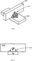
- Figs. 9 to 12 illustrate the angle bracket 100 in an installed configuration.
- Angle bracket 100 is seen joining a first construction element 200 to a second construction element 300.
- fastening means 55 in the form of screws are arranged in the smaller general apertures 50 of both the first leg 20 and the second leg 30.
- the very deliberate shape of angle bracket 100 provides the opportunity for positioning of the fastening means 55 in the apertures 50 of the angle bracket 100 so as to be more disposed towards the centre of the construction elements 200, 300. This assists in improving the resulting connection and its structural integrity.
- the construction elements 200, 300 are e.g. timber this central placement of the fastening means 55 also minimises the risk of splitting the timber.
- the angle bracket can preferably be produced by a method comprising the steps:
- the width of the angle bracket along the axis of the common bending line 40 is longer than the width of the free end part 25, 35 of a leg 20, 30.
- the material is deliberately positioned so as to maximise its use in the region around a line which extends from the mid-point of the common bending line 40, through the centroid and on to the free end part 25, 35 of each leg 20, 30, while reducing the length of parallel lines at the extremities (i.e. at the proximal and distal end of the common bending line 40).
- the angle bracket provides an optimised relationship between the load capacity of the angle bracket and the amount of material required with a rather surprising synergy. Surprisingly, it has been found by the applicant that the result is a reduction of up to 50% of the material compared with the existing prior art E5/1.5 angle bracket for the same mechanical resistance.
- angle bracket 100 shown in Figure 5 is formed from 1 mm thick steel.
- the flat (blank) component is an approximate 80x80mm square with chamfers at the apexes, then folded with a substantially 90° angle in the diagonal so to form the generally triangular shape of each leg 20, 30.
- the second leg 30 of the angle bracket 100 is to be fixed on the support, with a round aperture 38 for possible bolt connection.
- the first leg 20 is offered up to the truss and its oblong aperture 28 allows for sliding on its support.
- the first leg 20 and the second leg 30 are provided with a number of smaller fastener apertures 50 and two larger fastener apertures 28, 38.
- the smaller fastener apertures 50 could e.g. have a diameter of 5 mm, although any suitable diameter may be beneficially employed.
- the larger fastener apertures 28, 38 have different diameters, with aperture 28 being ⁇ 16mmx8mm and aperture 38 being ⁇ 10mm. Alternatively, the same diameter may be adopted for each aperture 28, 38.
- fastener aperture 28 is elongated so as to provide for tolerance adjustment on installation. Indeed, any suitable diameter/shape may be beneficially employed.
- At least one of the apertures of the first leg or the second leg may be larger than the others.
- different types of fastening means could be used e.g. nails and screws for the smaller apertures and a connector screw for the larger aperture.
- at least two apertures can be larger than the others, said two larger apertures having diameters that differ from each other.
- the at least two apertures could be placed on each leg. If only one of the larger apertures is used it is possible that, in use, the installer is free to orient the angle bracket according to the fastening means at hand.
- specifications could demand use of certain fastening means and the angle bracket being provided with apertures of different diameters would in this way be more likely to support the specifications.
- the angle bracket can be made from a rectangular piece of sheet metal. In this way, only the punched out material from the apertures is wasted. Furthermore, it is possible to use e.g. coils as raw material.
- the angle bracket can be made of galvanised high strength steel.
- the sheet metal can have a thickness of 0.5 - 5 mm, preferably 1 - 3.5 mm, most preferred 1 mm. Using galvanised steel, the angle bracket is better adapted to withstand corrosion. However, the combination of high strength steel with a thickness of e.g. 1 mm and the galvanisation gives the opportunity to reduce the thickness of the material used for the angle bracket.
- the preferred quality of the steel may be S250GD + Z275 according to EN10346:2004.
- one leg of the angle bracket may be longer than the other. If an angle bracket is used with a sill, on which a pillar or a stud is to be fastened, it is preferred that the one leg of the angle bracket extends the full distance from the lower part of the sill to a certain height on the pillar.
- the other leg does not necessarily need to be extended or to be longer if it is e.g. fastened by a threaded rod in concrete stemwalls.
- first leg 20 and second leg 30 of angles brackets 10, 100 may be provided with ribs along their side edges 22, 24, 32, 34 connected by common bending lines in the respective legs 20, 30 to provide yet further rigidity of the angle brackets 10, 100 and thus raising the moment of inertia of the angle brackets 10, 100 even further.
- angle bracket is used to join two construction elements, typically of timber.
- the angle bracket can be used in other applications as well.
- other materials used to form the construction elements may be used, such as concrete, metal, composite or any combination thereof.
Landscapes
- Engineering & Computer Science (AREA)
- General Engineering & Computer Science (AREA)
- Mechanical Engineering (AREA)
- Architecture (AREA)
- Physics & Mathematics (AREA)
- Electromagnetism (AREA)
- Civil Engineering (AREA)
- Structural Engineering (AREA)
- Joining Of Building Structures In Genera (AREA)
- Mutual Connection Of Rods And Tubes (AREA)
- Fencing (AREA)
Claims (15)
- Winkelhalter (10; 100) zum Verbinden eines ersten Konstruktionselements (200) mit einem zweiten Konstruktionselement (300), wobei der Winkelhalter (10; 100) umfasst:einen in einer ersten Ebene bereitgestellten ersten Schenkel (20), wobei der erste Schenkel (20) einen Verbindungsrand, welcher sich über eine Verbindungslänge (l1) in einer Längsachse (x) erstreckt, und einen ersten freien Endteil (25) distal von dem Verbindungsrand umfasst, wobei der erste Schenkel (20) einen Massenschwerpunkt (m1) und eine Höhe (h1) aufweist; undeinen in einer zweiten Ebene bereitgestellten zweiten Schenkel (30), wobei der zweite Schenkel (30) einen Verbindungsrand, welcher sich über eine Verbindungslänge (l1) in der Längsachse (x) erstreckt, und einen zweiten freien Endteil (35) distal von dem Verbindungsrand umfasst, wobei der zweite Schenkel (30) einen Massenschwerpunkt (m2) und eine Höhe (h2) aufweist, wobei:der erste Schenkel (20) und der zweite Schenkel (30) im Wesentlichen zueinander senkrecht mittels einer gemeinsamen Abwinklungslinie (40) angeordnet sind, wobei die gemeinsame Abwinklungslinie (40) die jeweiligen Verbindungsränder des ersten Schenkels (20) und des zweiten Schenkels (30) in der Längsachse (x) zusammenfügt oder verbindet;wenigstens ein Abschnitt des ersten Schenkels (20) zwischen dem Verbindungsrand und seinem Massenschwerpunkt (m1) in einer zu der Längsachse (x) parallelen Achse breiter ist als der breiteste Teil des ersten Schenkels (20) zwischen seinem Massenschwerpunkt (m1) und dem ersten freien Endteil (25);wenigstens ein Abschnitt des zweiten Schenkels (30) zwischen dem Verbindungsrand und seinem Massenschwerpunkt (m2) in einer zu der Längsachse (x) parallelen Achse breiter ist als der breiteste Teil des zweiten Schenkels (30) zwischen seinem Massenschwerpunkt (m2) und dem zweiten freien Endteil (35);die Verbindungslänge (l1) des Winkelhalters (10; 100) größer ist als die Höhe (h1) des ersten Schenkels (20) oder die Höhe (h2) des zweiten Schenkels (30); unddie gemeinsame Abwinklungslinie (40), welche sich in der Längsachse (x) erstreckt, der breiteste Teil des Winkelhalters (10; 100) in der Längsachse (x) oder dazu parallelen Längsachsen ausbildet und/oder definiert.
- Winkelhalter (10; 100) nach Anspruch 1, wobei die Höhe (h1) des ersten Schenkels (20) die gleiche wie die Höhe (h2) des zweiten Schenkels (30) ist.
- Winkelhalter (10; 100) nach Anspruch 1, wobei die Höhe (h1) des ersten Schenkels (20) nicht die gleiche wie die Höhe (h2) des zweiten Schenkels (30) ist.
- Winkelhalter (10; 100) nach einem der vorhergehenden Ansprüche, ferner umfassend eine Mehrzahl von Öffnungen (28; 38; 50) zum Aufnehmen von Mitteln (55), um bei einer Verwendung den ersten Schenkel (20) des Winkelhalters (10; 100) an einem ersten Konstruktionselement (200) und den zweiten Schenkel (30) des Winkelhalters (10; 100) an einem zweiten Konstruktionselement (300) zu befestigen.
- Winkelhalter (10; 100) nach einem der vorhergehenden Ansprüche, ferner umfassend eine oder mehrere Wülste (80, 90).
- Winkelhalter (10; 100) nach einem der vorhergehenden Ansprüche, wobei die Breite des Winkelhalters (10; 100) entlang der Achse des gemeinsamen Abwinklungsabschnitts (40) größer ist als die Breite jedes entsprechenden ersten und zweiten freien Endteils (25, 35).
- Winkelhalter (10; 100) nach einem der vorhergehenden Ansprüche, wobei jeder aus dem ersten Schenkel (20) und dem zweiten Schenkel (30) im Wesentlichen eine dreieckige Form aufweist.
- Winkelhalter (10; 100) nach einem der Ansprüche 4 bis 7, wobei wenigstens eine der Öffnungen (28; 38; 50) des ersten Schenkels (20) oder des zweiten Schenkels (30) größer ist als die anderen.
- Winkelhalter (10; 100) nach einem der Ansprüche 4 bis 8, wobei wenigstens zwei der Öffnungen (28; 38; 50) größer sind als die anderen, wobei zwei größeren Öffnungen Durchmesser aufweisen, welche sich voneinander unterscheiden.
- Winkelhalter (10; 100) nach einem der vorhergehenden Ansprüche, wobei der Winkelhalter (10; 100) aus einem rechteckigen Metallblechstück hergestellt oder ausgebildet ist.
- Winkelhalter (10; 100) nach einem der Ansprüche 1 bis 9, wobei der Winkelhalter (10; 100) aus einem polygonalen Metallblechstück hergestellt oder ausgebildet ist.
- Winkelhalter (10; 100) nach einem der vorhergehenden Ansprüche, wobei der Winkelhalter (10; 100) aus einem Metallblechstück hergestellt oder ausgebildet ist.
- Winkelhalter (10; 100) nach einem der vorhergehenden Ansprüche, wobei der Winkelhalter (10; 100) aus einem galvanisierten hochfesten Stahl hergestellt ist.
- Winkelhalter (10; 100) nach einem der vorhergehenden Ansprüche, wobei der Winkelhalter (10; 100) aus einem Metallblech mit einer Dicke von 0,5 - 5 mm, vorzugsweise von 1 - 3,5 mm, höchstvorzugsweise von 1 mm hergestellt ist.
- Winkelhalter (10; 100) zum Verbinden eines ersten Konstruktionselements (200) mit einem zweiten Konstruktionselement (300), wobei der Winkelhalter (10; 100) umfasst:einen in einer ersten Ebene bereitgestellten ersten Schenkel (20), wobei der erste Schenkel (20) einen Verbindungsrand, welcher sich über eine Verbindungslänge (l1) in einer Längsachse (x) erstreckt, und einen ersten freien Endteil (25) distal von dem Verbindungsrand umfasst, wobei der erste Schenkel (20) einen Flächenmittelpunkt (a1) und eine Höhe (h1) aufweist; undeinen in einer zweiten Ebene bereitgestellten zweiten Schenkel (30), wobei der zweite Schenkel (30) einen Verbindungsrand, welcher sich über eine Verbindungslänge (l1) in der Längsachse (x) erstreckt, und einen zweiten freien Endteil (35) distal von dem Verbindungsrand umfasst, wobei der zweite Schenkel (30) einen Flächenmittelpunkt (a2) und eine Höhe (h2) aufweist, wobei:der erste Schenkel (20) und der zweite Schenkel (30) im Wesentlichen zueinander senkrecht mittels einer gemeinsamen Abwinklungslinie (40) angeordnet sind, wobei die gemeinsame Abwinklungslinie (40) die jeweiligen Verbindungsränder des ersten Schenkels (20) und des zweiten Schenkels (30) in der Längsachse (x) zusammenfügt oder verbindet;wenigstens ein Abschnitt des ersten Schenkels (20) zwischen dem Verbindungsrand und seinem Flächenmittelpunkt (a1) in einer zu der Längsachse (x) parallelen Achse breiter ist als der breiteste Teil des ersten Schenkels (20) zwischen seinem Flächenmittelpunkt (a1) und dem ersten freien Endteil (25);wenigstens ein Abschnitt des zweiten Schenkels (30) zwischen dem Verbindungsrand und seinem Flächenmittelpunkt (a2) in einer zu der Längsachse (x) parallelen Achse breiter ist als der breiteste Teil des zweiten Schenkels (30) zwischen seinem Flächenmittelpunkt (a2) und dem zweiten freien Endteil (35);die Verbindungslänge (l1) des Winkelhalters (10; 100) größer ist als die Höhe (h1) des ersten Schenkels (20) oder die Höhe (h2) des zweiten Schenkels (30); unddie gemeinsame Abwinklungslinie (40), welche sich in der Längsachse (x) erstreckt, der breiteste Teil des Winkelhalters (10; 100) in der Längsachse (x) oder dazu parallelen Längsachsen ausbildet und/oder definiert.
Applications Claiming Priority (1)
| Application Number | Priority Date | Filing Date | Title |
|---|---|---|---|
| GB201102198A GB2487938B (en) | 2011-02-08 | 2011-02-08 | Angle bracket for fastening a first construction element to a second construction element and method for producing an angle bracket |
Publications (3)
| Publication Number | Publication Date |
|---|---|
| EP2546424A2 EP2546424A2 (de) | 2013-01-16 |
| EP2546424A3 EP2546424A3 (de) | 2014-02-26 |
| EP2546424B1 true EP2546424B1 (de) | 2018-10-10 |
Family
ID=43836412
Family Applications (1)
| Application Number | Title | Priority Date | Filing Date |
|---|---|---|---|
| EP12154582.6A Not-in-force EP2546424B1 (de) | 2011-02-08 | 2012-02-08 | Winkelträger zur Befestigung eines ersten Bauelements an ein zweites Bauelement und Verfahren zur Herstellung eines Winkelträgers |
Country Status (2)
| Country | Link |
|---|---|
| EP (1) | EP2546424B1 (de) |
| GB (1) | GB2487938B (de) |
Cited By (1)
| Publication number | Priority date | Publication date | Assignee | Title |
|---|---|---|---|---|
| FR3148207A1 (fr) * | 2023-04-26 | 2024-11-01 | Psa Automobiles Sa | Pièce d’implication de véhicule automobile, pour l’implication d’un longeron latéral dans un choc par l’avant |
Families Citing this family (4)
| Publication number | Priority date | Publication date | Assignee | Title |
|---|---|---|---|---|
| WO2017020098A1 (fr) | 2015-07-31 | 2017-02-09 | Delfeld Marc | Pièce de connexion |
| IT201700002109U1 (it) * | 2017-01-11 | 2018-07-11 | Thomas Schrentewein | Elemento di connessione per costruzioni in legno |
| US11719269B2 (en) * | 2021-07-12 | 2023-08-08 | Chiao-Yin CHANG | Corner bracket with reinforcing ribs |
| US20260055598A1 (en) * | 2024-08-20 | 2026-02-26 | Simpson Strong-Tie Company Inc. | Post Frame Column Base |
Family Cites Families (10)
| Publication number | Priority date | Publication date | Assignee | Title |
|---|---|---|---|---|
| US1225525A (en) * | 1914-05-25 | 1917-05-08 | Oliver T Sweet | Outlet-box and support therefor. |
| GB254434A (en) * | 1925-04-23 | 1926-07-08 | Arthur David Tipper | Improvements relating to sheet metal brackets |
| GB1070780A (en) * | 1964-12-03 | 1967-06-01 | Timber Engineerlng Company | Improvements in and relating to timber connectors |
| IE50239B1 (en) * | 1979-09-28 | 1986-03-05 | Press Bat Holdings Ltd | A joist support for use in building and a building structure including such a support |
| ZA947159B (en) * | 1993-09-22 | 1995-05-16 | Inntegra A G | Furniture kit |
| US6324810B1 (en) * | 1994-02-02 | 2001-12-04 | Thomas Thompson | Retrofit hurricane and earthquake protection |
| DE29713689U1 (de) * | 1997-08-01 | 1998-04-23 | Kellner, Peter, 36214 Nentershausen | Verbindungselement zum Verbinden von Teilen aus Holz, Kunststoff u.dgl. |
| US20020139765A1 (en) * | 2000-12-28 | 2002-10-03 | John Weider | Connector angle |
| DE202004005674U1 (de) * | 2004-04-07 | 2004-07-29 | Meldau, Heinrich, Dipl.-Des. | Möbelbeschlag |
| DE202006003432U1 (de) * | 2006-03-02 | 2006-06-01 | Alfer Aluminium Gesellschaft Mbh | Profilsystem |
-
2011
- 2011-02-08 GB GB201102198A patent/GB2487938B/en not_active Expired - Fee Related
-
2012
- 2012-02-08 EP EP12154582.6A patent/EP2546424B1/de not_active Not-in-force
Non-Patent Citations (1)
| Title |
|---|
| None * |
Cited By (1)
| Publication number | Priority date | Publication date | Assignee | Title |
|---|---|---|---|---|
| FR3148207A1 (fr) * | 2023-04-26 | 2024-11-01 | Psa Automobiles Sa | Pièce d’implication de véhicule automobile, pour l’implication d’un longeron latéral dans un choc par l’avant |
Also Published As
| Publication number | Publication date |
|---|---|
| GB2487938A (en) | 2012-08-15 |
| EP2546424A3 (de) | 2014-02-26 |
| GB2487938B (en) | 2014-02-19 |
| EP2546424A2 (de) | 2013-01-16 |
| GB201102198D0 (en) | 2011-03-23 |
Similar Documents
| Publication | Publication Date | Title |
|---|---|---|
| EP2546424B1 (de) | Winkelträger zur Befestigung eines ersten Bauelements an ein zweites Bauelement und Verfahren zur Herstellung eines Winkelträgers | |
| EP2499308A1 (de) | Strukturelle verstärkung | |
| US10900220B2 (en) | Concrete weldment | |
| US10858820B2 (en) | Reinforced beam system | |
| EP3631115B1 (de) | Gewelltes konstruktionselement, vorrichtung zur herstellung eines solchen und herstellungsverfahren | |
| WO2010059631A1 (en) | Metal stud | |
| AU2022381908A1 (en) | Improvements in, or relating to, a joint and system therefor | |
| CA3216961A1 (en) | A joist and nailer assembly having nailer plates and a method of assembling | |
| JP5216683B2 (ja) | 折板屋根の支持構造 | |
| JP5854657B2 (ja) | パイプサポート支持金具 | |
| AU2011253543B2 (en) | System and Method for Manufacturing Cellular Board | |
| AU2010242553A1 (en) | Construction element | |
| JP3126116U (ja) | 耐力壁パネル | |
| JPH11107368A (ja) | 筋かい固定金具及び筋かい固定構造 | |
| JP2017031784A (ja) | ブレース | |
| JP7745608B2 (ja) | 建築用ターンバックル | |
| EP2140952A2 (de) | Rollformverfahren zur Herstellung einer Senkrechtstützstruktur eines Palettengestell | |
| JP5738603B2 (ja) | 建築用パネルと建築部材のための固定金具、固定構造及び固定方法 | |
| KR101238837B1 (ko) | 아치형상의 구조용 집성재 성형장치 | |
| JP2587458Y2 (ja) | 足場つなぎ金具 | |
| JP7832439B2 (ja) | H形断面部材及び支持構造 | |
| AU2011204783B2 (en) | Formwork Assembly And Formwork Element For Casting Concrete Components | |
| EP2354376A2 (de) | Verstärkungsplatte | |
| JP3007389U (ja) | 木造建築物における土台と柱と筋交いの連結構造 | |
| JP4371735B2 (ja) | 型枠パネル支持鋼材 |
Legal Events
| Date | Code | Title | Description |
|---|---|---|---|
| PUAI | Public reference made under article 153(3) epc to a published international application that has entered the european phase |
Free format text: ORIGINAL CODE: 0009012 |
|
| AK | Designated contracting states |
Kind code of ref document: A2 Designated state(s): AL AT BE BG CH CY CZ DE DK EE ES FI FR GB GR HR HU IE IS IT LI LT LU LV MC MK MT NL NO PL PT RO RS SE SI SK SM TR |
|
| AX | Request for extension of the european patent |
Extension state: BA ME |
|
| PUAL | Search report despatched |
Free format text: ORIGINAL CODE: 0009013 |
|
| AK | Designated contracting states |
Kind code of ref document: A3 Designated state(s): AL AT BE BG CH CY CZ DE DK EE ES FI FR GB GR HR HU IE IS IT LI LT LU LV MC MK MT NL NO PL PT RO RS SE SI SK SM TR |
|
| AX | Request for extension of the european patent |
Extension state: BA ME |
|
| RIC1 | Information provided on ipc code assigned before grant |
Ipc: E04B 1/38 20060101ALI20140123BHEP Ipc: F16B 12/46 20060101ALI20140123BHEP Ipc: A47B 96/06 20060101ALI20140123BHEP Ipc: E04B 1/26 20060101AFI20140123BHEP |
|
| 17P | Request for examination filed |
Effective date: 20140804 |
|
| RBV | Designated contracting states (corrected) |
Designated state(s): AL AT BE BG CH CY CZ DE DK EE ES FI FR GB GR HR HU IE IS IT LI LT LU LV MC MK MT NL NO PL PT RO RS SE SI SK SM TR |
|
| 17Q | First examination report despatched |
Effective date: 20150415 |
|
| GRAP | Despatch of communication of intention to grant a patent |
Free format text: ORIGINAL CODE: EPIDOSNIGR1 |
|
| INTG | Intention to grant announced |
Effective date: 20160331 |
|
| GRAJ | Information related to disapproval of communication of intention to grant by the applicant or resumption of examination proceedings by the epo deleted |
Free format text: ORIGINAL CODE: EPIDOSDIGR1 |
|
| STAA | Information on the status of an ep patent application or granted ep patent |
Free format text: STATUS: EXAMINATION IS IN PROGRESS |
|
| GRAP | Despatch of communication of intention to grant a patent |
Free format text: ORIGINAL CODE: EPIDOSNIGR1 |
|
| STAA | Information on the status of an ep patent application or granted ep patent |
Free format text: STATUS: GRANT OF PATENT IS INTENDED |
|
| INTC | Intention to grant announced (deleted) | ||
| INTG | Intention to grant announced |
Effective date: 20161219 |
|
| GRAJ | Information related to disapproval of communication of intention to grant by the applicant or resumption of examination proceedings by the epo deleted |
Free format text: ORIGINAL CODE: EPIDOSDIGR1 |
|
| STAA | Information on the status of an ep patent application or granted ep patent |
Free format text: STATUS: EXAMINATION IS IN PROGRESS |
|
| GRAP | Despatch of communication of intention to grant a patent |
Free format text: ORIGINAL CODE: EPIDOSNIGR1 |
|
| STAA | Information on the status of an ep patent application or granted ep patent |
Free format text: STATUS: GRANT OF PATENT IS INTENDED |
|
| INTC | Intention to grant announced (deleted) | ||
| INTG | Intention to grant announced |
Effective date: 20170921 |
|
| GRAS | Grant fee paid |
Free format text: ORIGINAL CODE: EPIDOSNIGR3 |
|
| GRAA | (expected) grant |
Free format text: ORIGINAL CODE: 0009210 |
|
| STAA | Information on the status of an ep patent application or granted ep patent |
Free format text: STATUS: THE PATENT HAS BEEN GRANTED |
|
| AK | Designated contracting states |
Kind code of ref document: B1 Designated state(s): AL AT BE BG CH CY CZ DE DK EE ES FI FR GB GR HR HU IE IS IT LI LT LU LV MC MK MT NL NO PL PT RO RS SE SI SK SM TR |
|
| REG | Reference to a national code |
Ref country code: GB Ref legal event code: FG4D |
|
| REG | Reference to a national code |
Ref country code: CH Ref legal event code: EP Ref country code: AT Ref legal event code: REF Ref document number: 1051423 Country of ref document: AT Kind code of ref document: T Effective date: 20181015 |
|
| REG | Reference to a national code |
Ref country code: IE Ref legal event code: FG4D |
|
| REG | Reference to a national code |
Ref country code: DE Ref legal event code: R096 Ref document number: 602012051947 Country of ref document: DE |
|
| REG | Reference to a national code |
Ref country code: NL Ref legal event code: MP Effective date: 20181010 |
|
| REG | Reference to a national code |
Ref country code: LT Ref legal event code: MG4D |
|
| PG25 | Lapsed in a contracting state [announced via postgrant information from national office to epo] |
Ref country code: NL Free format text: LAPSE BECAUSE OF FAILURE TO SUBMIT A TRANSLATION OF THE DESCRIPTION OR TO PAY THE FEE WITHIN THE PRESCRIBED TIME-LIMIT Effective date: 20181010 |
|
| PG25 | Lapsed in a contracting state [announced via postgrant information from national office to epo] |
Ref country code: FI Free format text: LAPSE BECAUSE OF FAILURE TO SUBMIT A TRANSLATION OF THE DESCRIPTION OR TO PAY THE FEE WITHIN THE PRESCRIBED TIME-LIMIT Effective date: 20181010 Ref country code: IS Free format text: LAPSE BECAUSE OF FAILURE TO SUBMIT A TRANSLATION OF THE DESCRIPTION OR TO PAY THE FEE WITHIN THE PRESCRIBED TIME-LIMIT Effective date: 20190210 Ref country code: NO Free format text: LAPSE BECAUSE OF FAILURE TO SUBMIT A TRANSLATION OF THE DESCRIPTION OR TO PAY THE FEE WITHIN THE PRESCRIBED TIME-LIMIT Effective date: 20190110 Ref country code: ES Free format text: LAPSE BECAUSE OF FAILURE TO SUBMIT A TRANSLATION OF THE DESCRIPTION OR TO PAY THE FEE WITHIN THE PRESCRIBED TIME-LIMIT Effective date: 20181010 Ref country code: LV Free format text: LAPSE BECAUSE OF FAILURE TO SUBMIT A TRANSLATION OF THE DESCRIPTION OR TO PAY THE FEE WITHIN THE PRESCRIBED TIME-LIMIT Effective date: 20181010 Ref country code: HR Free format text: LAPSE BECAUSE OF FAILURE TO SUBMIT A TRANSLATION OF THE DESCRIPTION OR TO PAY THE FEE WITHIN THE PRESCRIBED TIME-LIMIT Effective date: 20181010 Ref country code: LT Free format text: LAPSE BECAUSE OF FAILURE TO SUBMIT A TRANSLATION OF THE DESCRIPTION OR TO PAY THE FEE WITHIN THE PRESCRIBED TIME-LIMIT Effective date: 20181010 Ref country code: PL Free format text: LAPSE BECAUSE OF FAILURE TO SUBMIT A TRANSLATION OF THE DESCRIPTION OR TO PAY THE FEE WITHIN THE PRESCRIBED TIME-LIMIT Effective date: 20181010 Ref country code: BG Free format text: LAPSE BECAUSE OF FAILURE TO SUBMIT A TRANSLATION OF THE DESCRIPTION OR TO PAY THE FEE WITHIN THE PRESCRIBED TIME-LIMIT Effective date: 20190110 |
|
| PG25 | Lapsed in a contracting state [announced via postgrant information from national office to epo] |
Ref country code: PT Free format text: LAPSE BECAUSE OF FAILURE TO SUBMIT A TRANSLATION OF THE DESCRIPTION OR TO PAY THE FEE WITHIN THE PRESCRIBED TIME-LIMIT Effective date: 20190210 Ref country code: SE Free format text: LAPSE BECAUSE OF FAILURE TO SUBMIT A TRANSLATION OF THE DESCRIPTION OR TO PAY THE FEE WITHIN THE PRESCRIBED TIME-LIMIT Effective date: 20181010 Ref country code: GR Free format text: LAPSE BECAUSE OF FAILURE TO SUBMIT A TRANSLATION OF THE DESCRIPTION OR TO PAY THE FEE WITHIN THE PRESCRIBED TIME-LIMIT Effective date: 20190111 Ref country code: AL Free format text: LAPSE BECAUSE OF FAILURE TO SUBMIT A TRANSLATION OF THE DESCRIPTION OR TO PAY THE FEE WITHIN THE PRESCRIBED TIME-LIMIT Effective date: 20181010 Ref country code: RS Free format text: LAPSE BECAUSE OF FAILURE TO SUBMIT A TRANSLATION OF THE DESCRIPTION OR TO PAY THE FEE WITHIN THE PRESCRIBED TIME-LIMIT Effective date: 20181010 |
|
| REG | Reference to a national code |
Ref country code: DE Ref legal event code: R097 Ref document number: 602012051947 Country of ref document: DE |
|
| REG | Reference to a national code |
Ref country code: AT Ref legal event code: UEP Ref document number: 1051423 Country of ref document: AT Kind code of ref document: T Effective date: 20181010 |
|
| PG25 | Lapsed in a contracting state [announced via postgrant information from national office to epo] |
Ref country code: CZ Free format text: LAPSE BECAUSE OF FAILURE TO SUBMIT A TRANSLATION OF THE DESCRIPTION OR TO PAY THE FEE WITHIN THE PRESCRIBED TIME-LIMIT Effective date: 20181010 Ref country code: DK Free format text: LAPSE BECAUSE OF FAILURE TO SUBMIT A TRANSLATION OF THE DESCRIPTION OR TO PAY THE FEE WITHIN THE PRESCRIBED TIME-LIMIT Effective date: 20181010 |
|
| PLBE | No opposition filed within time limit |
Free format text: ORIGINAL CODE: 0009261 |
|
| STAA | Information on the status of an ep patent application or granted ep patent |
Free format text: STATUS: NO OPPOSITION FILED WITHIN TIME LIMIT |
|
| PG25 | Lapsed in a contracting state [announced via postgrant information from national office to epo] |
Ref country code: EE Free format text: LAPSE BECAUSE OF FAILURE TO SUBMIT A TRANSLATION OF THE DESCRIPTION OR TO PAY THE FEE WITHIN THE PRESCRIBED TIME-LIMIT Effective date: 20181010 Ref country code: SM Free format text: LAPSE BECAUSE OF FAILURE TO SUBMIT A TRANSLATION OF THE DESCRIPTION OR TO PAY THE FEE WITHIN THE PRESCRIBED TIME-LIMIT Effective date: 20181010 Ref country code: SK Free format text: LAPSE BECAUSE OF FAILURE TO SUBMIT A TRANSLATION OF THE DESCRIPTION OR TO PAY THE FEE WITHIN THE PRESCRIBED TIME-LIMIT Effective date: 20181010 Ref country code: RO Free format text: LAPSE BECAUSE OF FAILURE TO SUBMIT A TRANSLATION OF THE DESCRIPTION OR TO PAY THE FEE WITHIN THE PRESCRIBED TIME-LIMIT Effective date: 20181010 |
|
| 26N | No opposition filed |
Effective date: 20190711 |
|
| REG | Reference to a national code |
Ref country code: CH Ref legal event code: PL |
|
| GBPC | Gb: european patent ceased through non-payment of renewal fee |
Effective date: 20190208 |
|
| PG25 | Lapsed in a contracting state [announced via postgrant information from national office to epo] |
Ref country code: LU Free format text: LAPSE BECAUSE OF NON-PAYMENT OF DUE FEES Effective date: 20190208 Ref country code: MC Free format text: LAPSE BECAUSE OF FAILURE TO SUBMIT A TRANSLATION OF THE DESCRIPTION OR TO PAY THE FEE WITHIN THE PRESCRIBED TIME-LIMIT Effective date: 20181010 Ref country code: SI Free format text: LAPSE BECAUSE OF FAILURE TO SUBMIT A TRANSLATION OF THE DESCRIPTION OR TO PAY THE FEE WITHIN THE PRESCRIBED TIME-LIMIT Effective date: 20181010 |
|
| REG | Reference to a national code |
Ref country code: IE Ref legal event code: MM4A |
|
| PG25 | Lapsed in a contracting state [announced via postgrant information from national office to epo] |
Ref country code: CH Free format text: LAPSE BECAUSE OF NON-PAYMENT OF DUE FEES Effective date: 20190228 Ref country code: LI Free format text: LAPSE BECAUSE OF NON-PAYMENT OF DUE FEES Effective date: 20190228 |
|
| PG25 | Lapsed in a contracting state [announced via postgrant information from national office to epo] |
Ref country code: GB Free format text: LAPSE BECAUSE OF NON-PAYMENT OF DUE FEES Effective date: 20190208 Ref country code: IE Free format text: LAPSE BECAUSE OF NON-PAYMENT OF DUE FEES Effective date: 20190208 |
|
| PG25 | Lapsed in a contracting state [announced via postgrant information from national office to epo] |
Ref country code: TR Free format text: LAPSE BECAUSE OF FAILURE TO SUBMIT A TRANSLATION OF THE DESCRIPTION OR TO PAY THE FEE WITHIN THE PRESCRIBED TIME-LIMIT Effective date: 20181010 |
|
| PG25 | Lapsed in a contracting state [announced via postgrant information from national office to epo] |
Ref country code: MT Free format text: LAPSE BECAUSE OF NON-PAYMENT OF DUE FEES Effective date: 20190208 |
|
| PG25 | Lapsed in a contracting state [announced via postgrant information from national office to epo] |
Ref country code: CY Free format text: LAPSE BECAUSE OF FAILURE TO SUBMIT A TRANSLATION OF THE DESCRIPTION OR TO PAY THE FEE WITHIN THE PRESCRIBED TIME-LIMIT Effective date: 20181010 |
|
| PG25 | Lapsed in a contracting state [announced via postgrant information from national office to epo] |
Ref country code: HU Free format text: LAPSE BECAUSE OF FAILURE TO SUBMIT A TRANSLATION OF THE DESCRIPTION OR TO PAY THE FEE WITHIN THE PRESCRIBED TIME-LIMIT; INVALID AB INITIO Effective date: 20120208 |
|
| PG25 | Lapsed in a contracting state [announced via postgrant information from national office to epo] |
Ref country code: MK Free format text: LAPSE BECAUSE OF FAILURE TO SUBMIT A TRANSLATION OF THE DESCRIPTION OR TO PAY THE FEE WITHIN THE PRESCRIBED TIME-LIMIT Effective date: 20181010 |
|
| PGFP | Annual fee paid to national office [announced via postgrant information from national office to epo] |
Ref country code: FR Payment date: 20230214 Year of fee payment: 12 Ref country code: AT Payment date: 20230220 Year of fee payment: 12 |
|
| PGFP | Annual fee paid to national office [announced via postgrant information from national office to epo] |
Ref country code: IT Payment date: 20230216 Year of fee payment: 12 Ref country code: DE Payment date: 20230217 Year of fee payment: 12 Ref country code: BE Payment date: 20230215 Year of fee payment: 12 |
|
| REG | Reference to a national code |
Ref country code: DE Ref legal event code: R119 Ref document number: 602012051947 Country of ref document: DE |
|
| REG | Reference to a national code |
Ref country code: AT Ref legal event code: MM01 Ref document number: 1051423 Country of ref document: AT Kind code of ref document: T Effective date: 20240208 |
|
| PG25 | Lapsed in a contracting state [announced via postgrant information from national office to epo] |
Ref country code: AT Free format text: LAPSE BECAUSE OF NON-PAYMENT OF DUE FEES Effective date: 20240208 |
|
| PG25 | Lapsed in a contracting state [announced via postgrant information from national office to epo] |
Ref country code: AT Free format text: LAPSE BECAUSE OF NON-PAYMENT OF DUE FEES Effective date: 20240208 |
|
| REG | Reference to a national code |
Ref country code: BE Ref legal event code: MM Effective date: 20240229 |
|
| PG25 | Lapsed in a contracting state [announced via postgrant information from national office to epo] |
Ref country code: DE Free format text: LAPSE BECAUSE OF NON-PAYMENT OF DUE FEES Effective date: 20240903 |
|
| PG25 | Lapsed in a contracting state [announced via postgrant information from national office to epo] |
Ref country code: BE Free format text: LAPSE BECAUSE OF NON-PAYMENT OF DUE FEES Effective date: 20240229 |
|
| PG25 | Lapsed in a contracting state [announced via postgrant information from national office to epo] |
Ref country code: FR Free format text: LAPSE BECAUSE OF NON-PAYMENT OF DUE FEES Effective date: 20240229 |
|
| PG25 | Lapsed in a contracting state [announced via postgrant information from national office to epo] |
Ref country code: FR Free format text: LAPSE BECAUSE OF NON-PAYMENT OF DUE FEES Effective date: 20240229 Ref country code: DE Free format text: LAPSE BECAUSE OF NON-PAYMENT OF DUE FEES Effective date: 20240903 Ref country code: BE Free format text: LAPSE BECAUSE OF NON-PAYMENT OF DUE FEES Effective date: 20240229 |
|
| PG25 | Lapsed in a contracting state [announced via postgrant information from national office to epo] |
Ref country code: IT Free format text: LAPSE BECAUSE OF NON-PAYMENT OF DUE FEES Effective date: 20240208 |