EP2546529A2 - Système de soufflage d'un fluide, compresseur et turbomachine - Google Patents
Système de soufflage d'un fluide, compresseur et turbomachine Download PDFInfo
- Publication number
- EP2546529A2 EP2546529A2 EP12005134A EP12005134A EP2546529A2 EP 2546529 A2 EP2546529 A2 EP 2546529A2 EP 12005134 A EP12005134 A EP 12005134A EP 12005134 A EP12005134 A EP 12005134A EP 2546529 A2 EP2546529 A2 EP 2546529A2
- Authority
- EP
- European Patent Office
- Prior art keywords
- nozzles
- nozzle
- flow
- compressor
- turbomachine
- Prior art date
- Legal status (The legal status is an assumption and is not a legal conclusion. Google has not performed a legal analysis and makes no representation as to the accuracy of the status listed.)
- Withdrawn
Links
- 239000012530 fluid Substances 0.000 title claims description 21
- 238000011144 upstream manufacturing Methods 0.000 claims abstract description 6
- 238000002347 injection Methods 0.000 claims description 13
- 239000007924 injection Substances 0.000 claims description 13
- 238000007664 blowing Methods 0.000 description 4
- 238000000926 separation method Methods 0.000 description 3
- 238000005086 pumping Methods 0.000 description 2
- 230000002411 adverse Effects 0.000 description 1
- 238000001514 detection method Methods 0.000 description 1
- 230000000694 effects Effects 0.000 description 1
- 230000002093 peripheral effect Effects 0.000 description 1
Images

Classifications
-
- F—MECHANICAL ENGINEERING; LIGHTING; HEATING; WEAPONS; BLASTING
- F02—COMBUSTION ENGINES; HOT-GAS OR COMBUSTION-PRODUCT ENGINE PLANTS
- F02C—GAS-TURBINE PLANTS; AIR INTAKES FOR JET-PROPULSION PLANTS; CONTROLLING FUEL SUPPLY IN AIR-BREATHING JET-PROPULSION PLANTS
- F02C7/00—Features, components parts, details or accessories, not provided for in, or of interest apart form groups F02C1/00 - F02C6/00; Air intakes for jet-propulsion plants
- F02C7/22—Fuel supply systems
-
- F—MECHANICAL ENGINEERING; LIGHTING; HEATING; WEAPONS; BLASTING
- F04—POSITIVE - DISPLACEMENT MACHINES FOR LIQUIDS; PUMPS FOR LIQUIDS OR ELASTIC FLUIDS
- F04D—NON-POSITIVE-DISPLACEMENT PUMPS
- F04D27/00—Control, e.g. regulation, of pumps, pumping installations or pumping systems specially adapted for elastic fluids
- F04D27/02—Surge control
- F04D27/0207—Surge control by bleeding, bypassing or recycling fluids
- F04D27/0238—Details or means for fluid reinjection
-
- F—MECHANICAL ENGINEERING; LIGHTING; HEATING; WEAPONS; BLASTING
- F04—POSITIVE - DISPLACEMENT MACHINES FOR LIQUIDS; PUMPS FOR LIQUIDS OR ELASTIC FLUIDS
- F04D—NON-POSITIVE-DISPLACEMENT PUMPS
- F04D29/00—Details, component parts, or accessories
- F04D29/40—Casings; Connections of working fluid
- F04D29/52—Casings; Connections of working fluid for axial pumps
- F04D29/522—Casings; Connections of working fluid for axial pumps especially adapted for elastic fluid pumps
- F04D29/526—Details of the casing section radially opposing blade tips
-
- F—MECHANICAL ENGINEERING; LIGHTING; HEATING; WEAPONS; BLASTING
- F04—POSITIVE - DISPLACEMENT MACHINES FOR LIQUIDS; PUMPS FOR LIQUIDS OR ELASTIC FLUIDS
- F04D—NON-POSITIVE-DISPLACEMENT PUMPS
- F04D29/00—Details, component parts, or accessories
- F04D29/66—Combating cavitation, whirls, noise, vibration or the like; Balancing
- F04D29/661—Combating cavitation, whirls, noise, vibration or the like; Balancing especially adapted for elastic fluid pumps
- F04D29/667—Combating cavitation, whirls, noise, vibration or the like; Balancing especially adapted for elastic fluid pumps by influencing the flow pattern, e.g. suppression of turbulence
-
- F—MECHANICAL ENGINEERING; LIGHTING; HEATING; WEAPONS; BLASTING
- F04—POSITIVE - DISPLACEMENT MACHINES FOR LIQUIDS; PUMPS FOR LIQUIDS OR ELASTIC FLUIDS
- F04D—NON-POSITIVE-DISPLACEMENT PUMPS
- F04D29/00—Details, component parts, or accessories
- F04D29/66—Combating cavitation, whirls, noise, vibration or the like; Balancing
- F04D29/68—Combating cavitation, whirls, noise, vibration or the like; Balancing by influencing boundary layers
- F04D29/681—Combating cavitation, whirls, noise, vibration or the like; Balancing by influencing boundary layers especially adapted for elastic fluid pumps
- F04D29/684—Combating cavitation, whirls, noise, vibration or the like; Balancing by influencing boundary layers especially adapted for elastic fluid pumps by fluid injection
-
- F—MECHANICAL ENGINEERING; LIGHTING; HEATING; WEAPONS; BLASTING
- F05—INDEXING SCHEMES RELATING TO ENGINES OR PUMPS IN VARIOUS SUBCLASSES OF CLASSES F01-F04
- F05D—INDEXING SCHEME FOR ASPECTS RELATING TO NON-POSITIVE-DISPLACEMENT MACHINES OR ENGINES, GAS-TURBINES OR JET-PROPULSION PLANTS
- F05D2270/00—Control
- F05D2270/01—Purpose of the control system
- F05D2270/10—Purpose of the control system to cope with, or avoid, compressor flow instabilities
- F05D2270/101—Compressor surge or stall
- F05D2270/102—Compressor surge or stall caused by working fluid flow velocity profile distortion
Definitions
- the invention relates to a system for injecting a fluid into a wall boundary layer of a flow in a turbomachine.
- compressors in turbomachinery can regularly operate when operating the compressor outside a design point of the blades a so-called compressor pumps, in which the pressure in the compressor as a result of flow separation on the blades from rear to front degrades and a return flow is formed.
- a compressor pumping adversely affects the efficiency of the turbomachine.
- high loads occur in the blading, which are in part due to swinging or fluttering during the backflow phase.
- the risk of flow separation can be reduced if a wall boundary layer of the annular space flow is energized.
- the energization of the wall boundary layer can take place on the one hand by passive systems such as stator-side ribs or depressions.
- active systems which provide a blowing of a fluid through a plurality of circumferentially arranged nozzles in the annulus flow.
- Known active systems have nozzles with a round cross-section, which, however, only a very limited energizing of the wall boundary layer takes place and also high mixing losses occur.
- such high nozzle cross-sections cause a relatively strong reaction of the annular space flow on the nozzle flow.
- the object of the invention is to provide a system for blowing a fluid into a wall boundary layer of a flow in a turbomachine, which eliminates the aforementioned disadvantages and allows better energization and a reduction of mixing losses. Furthermore, it is an object of the invention to provide a compressor with a higher surge limit and a turbomachine with improved efficiency.
- a system for injecting a fluid into a wall boundary layer of a flow in a turbomachine has a plurality of nozzles arranged in a flow-restricting sidewall and oriented obliquely in the flow direction.
- the nozzles each have a rectangular flat nozzle cross-section.
- the rectangular flat and in particular slit-like nozzle cross-section of the so-called Coanda effect is improved and utilized more efficiently, creating an improved Energetistechnik the wall boundary layer occurs with minimal mixing losses.
- Efficiency can be further increased if, in each case, an injection channel with a bottleneck forming an interface is arranged upstream of the nozzles.
- the constriction allows the nozzle to have a low annulus pressure, thus placing a surge of pressure away from the sidewall into the nozzle.
- the fluid to be injected occurs perpendicular to the interface, whereby it is coupled without refraction in the nozzle.
- the interface defines the nozzle cross-section and the fluid in the nozzles or nozzle flow is not subject to additional pressure or velocity detection.
- constriction can be made aerodynamic, if the injection channel tapers in the direction of the constriction wedge or funnel-shaped
- the nozzles are made flat in the flow direction, since the fluid is thereby blown almost in the axial direction of the flow.
- the nozzles are set at an angle ⁇ 40 ° in the flow direction. Preferably, they are employed at an angle of 30 ° in the flow direction.
- nozzle exit surfaces are oriented tangentially to the direction of rotation. whereby the nozzle flow is swirl-free blown into the flow.
- the nozzle exit surfaces can be turned to the direction of rotation. They can be employed both in the direction of rotation and against the direction of rotation. For example, they are oriented at an angle of 20 ° in or against the direction of rotation.
- a compressor according to the invention has a system according to the invention for injecting a fluid into a wall boundary layer.
- Such a compressor is characterized by a significantly expanded pumping limit and thus by a high compressor stability and a reduced blade load.
- the compressor stability can be effectively increased even with a minimum amount of fluid when the system is positioned with its nozzles opposite the blade areas where flow separation is expected.
- the nozzles are therefore arranged on the stator side in the region of trailing edges of at least one blade row formed by rotor blades.
- a turbomachine according to the invention has a compressor according to the invention.
- Such a turbomachine is characterized by low efficiency losses and thus by a high efficiency, since the energization of the wall boundary layer improved and mixing losses are reduced.
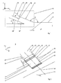
- FIG. 1 shows a partial section through an annular space 1 of a compressor of an aircraft engine.
- the annular space 1, in which the low annular space pressure p1 prevails, is radially bounded by a side wall 2 and flows through a flow 4 oriented in the longitudinal direction x of the aircraft engine.
- a dashed framed system 6 with a plurality of nozzles 8 and with a plurality of injection channels 10 is arranged on the circumference.
- the system 6 is used to energize a wall boundary layer of the flow 4 and allows injection of a fluid 12 with a high injection pressure p 2 into the annular space 1.
- the nozzles 8 are evenly spaced from each other distributed over the circumference of the annular space 1. They are each located downstream of a blow-in channel 10 and open into the annulus 1. As in FIG. 2 shown, they have a nozzle longitudinal axis xd, which is employed obliquely to the longitudinal axis x of the aircraft engine and thus to the flow 4.
- the nozzles 8 each have two lateral walls 14, 16 as well as a radially inner or inner wall 18 and a radially outer or outer wall 20.
- the walls 14, 16, 18, 20 define a rectangular flat and constant nozzle cross section shown in longitudinal cross-section 22.
- the blowing channels 10 are arranged between the nozzles 8 and a blower, not shown. As in FIG. 2 they each have two lateral walls 24, 26 and a radially inner wall 28 and a radially outer wall 30.
- the walls 24, 26, 28, 30 define a tapered in the flow direction rectangular cross-section.
- the lateral walls 24, 26 and the inner wall 28 are oriented parallel to the nozzle longitudinal axis xd and go flush in the lateral Düsenwauditch 14, 16 and in the inner nozzle wall 18 via.
- the outer wall 30 of the injection channels 10 is oriented obliquely in the direction of the nozzle longitudinal axis xd, whereby a cross-sectional taper formed in FIG. 1 figured bottleneck 32 is created, which defines an orthogonal to the nozzle longitudinal axis xd employed interface 34.
- the boundary surface 34 separates the high injection pressure p 2 from the low annulus pressure p 1, based on the pressure conditions.
- the high injection pressure p 2 prevails upstream of the interface 34 in the injection channels 10.
- the low annulus pressure p1 prevails downstream of the interface 34 in the nozzles 8 and in the annulus 1.
- the interface 34 forms a parting plane between two differently dense media 4, 12 or fluids, wherein, however, the fluid 12 is coupled into the thinner medium 4 without refraction due to the orientation of the interface 34 orthogonal to the nozzle longitudinal axis xd.
- the nozzle longitudinal axis xd is made flat to the longitudinal axis x of the aircraft engine.
- "Flat” means in an outer angle ⁇ between the side wall 2 and the outer nozzle wall 20 with ⁇ ⁇ 150 °.
- the annulus 1, as in FIG. 1 shown may be radially expanded downstream of the nozzle 8, so that a partial flow of the fluid 12 and a nozzle flow is injected axially or quasi axially into the wall boundary layer.
- the nozzle 8 each have a in FIG. 2 cross-hatched nozzle exit surface 36. This opens, as in the FIGS. 3, 4 and 5 shown, in each case radially opposite a trailing edge region 38 of a blade row formed by blades 40 in the annular space. 1
- the nozzle exit surfaces 36 run tangentially in the circumferential direction y and thus tangentially to the direction of rotation.
- the nozzle exit surfaces 36 are employed for swirling the fluid 12 through an angle ⁇ in the direction of rotation.
- the nozzle exit surfaces 36 are employed for swirling the fluid 12 through an angle ⁇ against the direction of rotation.
- a system for injecting a fluid into a wall boundary layer of a flow in a turbomachine having a plurality of nozzles disposed in a flow restricting sidewall and oriented obliquely in the flow direction, the nozzles each having a rectangular flat nozzle cross section, a compressor with such a system and a turbomachine with such a compressor.
Landscapes
- Engineering & Computer Science (AREA)
- Mechanical Engineering (AREA)
- General Engineering & Computer Science (AREA)
- Chemical & Material Sciences (AREA)
- Combustion & Propulsion (AREA)
- Life Sciences & Earth Sciences (AREA)
- Sustainable Development (AREA)
- Structures Of Non-Positive Displacement Pumps (AREA)
Applications Claiming Priority (1)
| Application Number | Priority Date | Filing Date | Title |
|---|---|---|---|
| DE102011107523.6A DE102011107523B4 (de) | 2011-07-15 | 2011-07-15 | System zum Einblasen eines Fluids, Verdichter sowie Turbomaschine |
Publications (2)
| Publication Number | Publication Date |
|---|---|
| EP2546529A2 true EP2546529A2 (fr) | 2013-01-16 |
| EP2546529A3 EP2546529A3 (fr) | 2018-04-04 |
Family
ID=46581693
Family Applications (1)
| Application Number | Title | Priority Date | Filing Date |
|---|---|---|---|
| EP12005134.7A Withdrawn EP2546529A3 (fr) | 2011-07-15 | 2012-07-12 | Système de soufflage d'un fluide, compresseur et turbomachine |
Country Status (3)
| Country | Link |
|---|---|
| US (1) | US9074533B2 (fr) |
| EP (1) | EP2546529A3 (fr) |
| DE (1) | DE102011107523B4 (fr) |
Families Citing this family (3)
| Publication number | Priority date | Publication date | Assignee | Title |
|---|---|---|---|---|
| US9567942B1 (en) * | 2010-12-02 | 2017-02-14 | Concepts Nrec, Llc | Centrifugal turbomachines having extended performance ranges |
| US12134984B1 (en) | 2023-11-17 | 2024-11-05 | Rtx Corporation | Fluidic compressor inlet guide vanes |
| US12215624B1 (en) | 2023-11-17 | 2025-02-04 | Rtx Corporation | Fluidic compressor inlet guide vane |
Citations (1)
| Publication number | Priority date | Publication date | Assignee | Title |
|---|---|---|---|---|
| DE102008052372A1 (de) | 2008-10-20 | 2010-04-22 | Mtu Aero Engines Gmbh | Verdichter |
Family Cites Families (15)
| Publication number | Priority date | Publication date | Assignee | Title |
|---|---|---|---|---|
| GB1518293A (en) * | 1975-09-25 | 1978-07-19 | Rolls Royce | Axial flow compressors particularly for gas turbine engines |
| KR100198721B1 (ko) * | 1991-01-30 | 1999-06-15 | 레비스 스테픈 이 | 개선된 케이스를 갖는 가스 터어빈 엔진 |
| RU2034175C1 (ru) * | 1993-03-11 | 1995-04-30 | Центральный институт авиационного моторостроения им.П.И.Баранова | Турбокомпрессор |
| US6574965B1 (en) * | 1998-12-23 | 2003-06-10 | United Technologies Corporation | Rotor tip bleed in gas turbine engines |
| US6585479B2 (en) * | 2001-08-14 | 2003-07-01 | United Technologies Corporation | Casing treatment for compressors |
| DE102004030597A1 (de) * | 2004-06-24 | 2006-01-26 | Rolls-Royce Deutschland Ltd & Co Kg | Strömungsarbeitsmaschine mit Aussenradstrahlerzeugung am Stator |
| DE102004055439A1 (de) * | 2004-11-17 | 2006-05-24 | Rolls-Royce Deutschland Ltd & Co Kg | Strömungsarbeitsmaschine mit dynamischer Strömungsbeeinflussung |
| DE102007037924A1 (de) * | 2007-08-10 | 2009-02-12 | Rolls-Royce Deutschland Ltd & Co Kg | Strömungsarbeitsmaschine mit Ringkanalwandausnehmung |
| DE102008014957A1 (de) * | 2008-03-19 | 2009-09-24 | Rolls-Royce Deutschland Ltd & Co Kg | Gasturbinenverdichter mit Zapfluftentnahme |
| DE102008015207A1 (de) * | 2008-03-20 | 2009-09-24 | Rolls-Royce Deutschland Ltd & Co Kg | Fluid-Injektor-Düse |
| DE102008016800A1 (de) * | 2008-04-02 | 2009-10-08 | Mtu Aero Engines Gmbh | Gasturbinenverdichter |
| DE102008017844A1 (de) * | 2008-04-08 | 2009-10-15 | Rolls-Royce Deutschland Ltd & Co Kg | Strömungsmaschine mit Fluid-Injektorbaugruppe |
| DE102008029605A1 (de) * | 2008-06-23 | 2009-12-24 | Rolls-Royce Deutschland Ltd & Co Kg | Schaufeldeckband mit Durchlass |
| DE102008037154A1 (de) * | 2008-08-08 | 2010-02-11 | Rolls-Royce Deutschland Ltd & Co Kg | Strömungsarbeitsmaschine |
| DE102008061184A1 (de) * | 2008-12-09 | 2010-06-10 | Mtu Aero Engines Gmbh | Verdichter |
-
2011
- 2011-07-15 DE DE102011107523.6A patent/DE102011107523B4/de not_active Expired - Fee Related
-
2012
- 2012-07-12 EP EP12005134.7A patent/EP2546529A3/fr not_active Withdrawn
- 2012-07-13 US US13/549,074 patent/US9074533B2/en not_active Expired - Fee Related
Patent Citations (1)
| Publication number | Priority date | Publication date | Assignee | Title |
|---|---|---|---|---|
| DE102008052372A1 (de) | 2008-10-20 | 2010-04-22 | Mtu Aero Engines Gmbh | Verdichter |
Also Published As
| Publication number | Publication date |
|---|---|
| US9074533B2 (en) | 2015-07-07 |
| EP2546529A3 (fr) | 2018-04-04 |
| DE102011107523A1 (de) | 2013-01-17 |
| DE102011107523B4 (de) | 2016-08-11 |
| US20130180249A1 (en) | 2013-07-18 |
Similar Documents
| Publication | Publication Date | Title |
|---|---|---|
| DE60319606T2 (de) | Abblassystem für die Statorstufe eines Verdichters | |
| EP2669474B1 (fr) | Canal de passage pour une turbomachine et turbomachine | |
| EP2696029B1 (fr) | Grille d'aube avec définition de contour de la paroi latérale et turbomachine | |
| WO2008046389A1 (fr) | Ensemble influençant un écoulement au moyen de géométries qui influencent la couche limite | |
| EP0902164A1 (fr) | Refroidissement de la platte-forme dans les turbines à gas | |
| EP3290644B1 (fr) | Turbine à gaz | |
| EP3121373B1 (fr) | Roue de turbine refroidie, plus particulièrement pour un réacteur | |
| EP3404269B1 (fr) | Dispositif formant ventilateur pourvu de buse de division d'écoulement | |
| WO2011054812A2 (fr) | Turbomachine à compression ou expansion axiale | |
| EP0799973A1 (fr) | Contour de paroi pour une turbomachine axiale | |
| WO2011058034A1 (fr) | Fond intermédiaire pour une turbomachine radiale | |
| EP2788583B1 (fr) | Aube directrice de turbine dotée d'un élément d'étranglement | |
| DE102011107523B4 (de) | System zum Einblasen eines Fluids, Verdichter sowie Turbomaschine | |
| WO2013107489A1 (fr) | Procédé et dispositif pour stabiliser un flux de compresseur | |
| WO2006024273A1 (fr) | Rotor pour un propulseur | |
| EP2584148A1 (fr) | Aube de turbine refroidie par film pour une turbomachine | |
| EP3682119A1 (fr) | Diffuseur pour compresseur radial | |
| DE102015110249A1 (de) | Statorvorrichtung für eine Strömungsmaschine mit einer Gehäuseeinrichtung und mehreren Leitschaufeln | |
| EP3473808A1 (fr) | Pale d'aube pour une aube mobile de turbine à refroidissement intérieur ainsi que procédé de fabrication d'une telle pale | |
| EP3109520B1 (fr) | Support d'étanchéité, stator et turbomachine | |
| EP3495639B1 (fr) | Module de compresseur pour une turbomachine réduisant la couche limite dans un carter intermédiaire de compresseur | |
| EP1632648B1 (fr) | Turbine à gaz comprenant un conduit de transition | |
| WO2021037296A1 (fr) | Pale de rotor de compresseur | |
| DE102015110250A1 (de) | Statorvorrichtung für eine Strömungsmaschine mit einer Gehäuseeinrichtung und mehreren Leitschaufeln | |
| EP3404211A1 (fr) | Segment de grille d'aubes d'une turbine avec paroi de plateforme contourée, grille d'aubes, canal d'aube, plateforme, turbine et moteur d'aéronef associés |
Legal Events
| Date | Code | Title | Description |
|---|---|---|---|
| PUAI | Public reference made under article 153(3) epc to a published international application that has entered the european phase |
Free format text: ORIGINAL CODE: 0009012 |
|
| AK | Designated contracting states |
Kind code of ref document: A2 Designated state(s): AL AT BE BG CH CY CZ DE DK EE ES FI FR GB GR HR HU IE IS IT LI LT LU LV MC MK MT NL NO PL PT RO RS SE SI SK SM TR |
|
| AX | Request for extension of the european patent |
Extension state: BA ME |
|
| RAP1 | Party data changed (applicant data changed or rights of an application transferred) |
Owner name: MTU AERO ENGINES GMBH |
|
| RAP1 | Party data changed (applicant data changed or rights of an application transferred) |
Owner name: MTU AERO ENGINES AG |
|
| PUAL | Search report despatched |
Free format text: ORIGINAL CODE: 0009013 |
|
| AK | Designated contracting states |
Kind code of ref document: A3 Designated state(s): AL AT BE BG CH CY CZ DE DK EE ES FI FR GB GR HR HU IE IS IT LI LT LU LV MC MK MT NL NO PL PT RO RS SE SI SK SM TR |
|
| AX | Request for extension of the european patent |
Extension state: BA ME |
|
| RIC1 | Information provided on ipc code assigned before grant |
Ipc: F04D 29/68 20060101ALI20180301BHEP Ipc: F04D 29/52 20060101ALI20180301BHEP Ipc: F04D 29/66 20060101AFI20180301BHEP Ipc: F04D 27/02 20060101ALI20180301BHEP |
|
| STAA | Information on the status of an ep patent application or granted ep patent |
Free format text: STATUS: REQUEST FOR EXAMINATION WAS MADE |
|
| 17P | Request for examination filed |
Effective date: 20181004 |
|
| RBV | Designated contracting states (corrected) |
Designated state(s): AL AT BE BG CH CY CZ DE DK EE ES FI FR GB GR HR HU IE IS IT LI LT LU LV MC MK MT NL NO PL PT RO RS SE SI SK SM TR |
|
| GRAP | Despatch of communication of intention to grant a patent |
Free format text: ORIGINAL CODE: EPIDOSNIGR1 |
|
| STAA | Information on the status of an ep patent application or granted ep patent |
Free format text: STATUS: GRANT OF PATENT IS INTENDED |
|
| INTG | Intention to grant announced |
Effective date: 20181219 |
|
| GRAS | Grant fee paid |
Free format text: ORIGINAL CODE: EPIDOSNIGR3 |
|
| STAA | Information on the status of an ep patent application or granted ep patent |
Free format text: STATUS: THE APPLICATION IS DEEMED TO BE WITHDRAWN |
|
| 18D | Application deemed to be withdrawn |
Effective date: 20190430 |