EP2549257A1 - Procédé de détection de dommages sur des engrenages - Google Patents
Procédé de détection de dommages sur des engrenages Download PDFInfo
- Publication number
- EP2549257A1 EP2549257A1 EP11174330A EP11174330A EP2549257A1 EP 2549257 A1 EP2549257 A1 EP 2549257A1 EP 11174330 A EP11174330 A EP 11174330A EP 11174330 A EP11174330 A EP 11174330A EP 2549257 A1 EP2549257 A1 EP 2549257A1
- Authority
- EP
- European Patent Office
- Prior art keywords
- vibration
- vibration signal
- meshing
- detected
- signal
- Prior art date
- Legal status (The legal status is an assumption and is not a legal conclusion. Google has not performed a legal analysis and makes no representation as to the accuracy of the status listed.)
- Granted
Links
- 238000000034 method Methods 0.000 title claims abstract description 30
- 230000005540 biological transmission Effects 0.000 claims abstract description 49
- 230000010355 oscillation Effects 0.000 claims abstract description 27
- 238000012544 monitoring process Methods 0.000 claims description 20
- 238000011156 evaluation Methods 0.000 claims description 11
- 238000005096 rolling process Methods 0.000 claims description 9
- 238000001514 detection method Methods 0.000 description 16
- 238000004458 analytical method Methods 0.000 description 12
- 230000001419 dependent effect Effects 0.000 description 9
- 230000008859 change Effects 0.000 description 6
- 230000000875 corresponding effect Effects 0.000 description 6
- 239000003921 oil Substances 0.000 description 4
- 230000007423 decrease Effects 0.000 description 3
- 238000005259 measurement Methods 0.000 description 3
- 230000002596 correlated effect Effects 0.000 description 2
- 239000012208 gear oil Substances 0.000 description 2
- 238000012067 mathematical method Methods 0.000 description 2
- 230000036962 time dependent Effects 0.000 description 2
- 238000012546 transfer Methods 0.000 description 2
- 230000009466 transformation Effects 0.000 description 2
- 238000012935 Averaging Methods 0.000 description 1
- 238000013459 approach Methods 0.000 description 1
- 238000003745 diagnosis Methods 0.000 description 1
- 238000010586 diagram Methods 0.000 description 1
- 230000001771 impaired effect Effects 0.000 description 1
- 230000007257 malfunction Effects 0.000 description 1
- 238000013508 migration Methods 0.000 description 1
- 230000005012 migration Effects 0.000 description 1
- 238000012986 modification Methods 0.000 description 1
- 230000004048 modification Effects 0.000 description 1
- 238000004393 prognosis Methods 0.000 description 1
- 230000008439 repair process Effects 0.000 description 1
- 238000000926 separation method Methods 0.000 description 1
- 238000004088 simulation Methods 0.000 description 1
- 238000001228 spectrum Methods 0.000 description 1
Images

Classifications
-
- G—PHYSICS
- G01—MEASURING; TESTING
- G01M—TESTING STATIC OR DYNAMIC BALANCE OF MACHINES OR STRUCTURES; TESTING OF STRUCTURES OR APPARATUS, NOT OTHERWISE PROVIDED FOR
- G01M13/00—Testing of machine parts
- G01M13/02—Gearings; Transmission mechanisms
- G01M13/028—Acoustic or vibration analysis
Definitions
- the invention relates to a method for detecting damage in geared gear stages with at least one pair of meshing gears, in which by at least one vibration sensor vibration signals are detected, which correspond to the vibrations occurring during operation of the gear stage, and the detected vibration signals are analyzed to to detect possible damage. Furthermore, the invention relates to a device for damage detection geared gear stages.
- condition monitoring systems are used, with which it can be monitored during operation, whether a component, such as a gear, works properly or a malfunction exists or develops such.
- the occurrence or imminence of damage can be detected early in this way, so that appropriate measures can be taken to limit the damage locally or to correct it promptly and efficiently.
- Operational restrictions or downtime of the machine can be kept low.
- condition monitoring systems are gaining in importance, in particular in the context of energy generation by wind power, since the permanent reliable operation of the wind power plant for continuous power supply must be ensured and is a prerequisite for economic operation of the plant.
- condition monitoring of the transmission because the transmission of the wind turbine shows the highest downtime per case of damage among the components of wind turbines. The long downtime is due to complex repair procedures and sometimes poor accessibility of the damaged components.
- a condition monitoring system as used in the field of wind power, generally includes temperature monitoring of the plant, condition monitoring of the oil used in the plant, and vibration monitoring.
- the vibrations associated with the operation of a component are monitored by means of suitable vibration sensors so as to be able to detect deviations from the normal operation of the wind power plant or its components, which indicate a present damage.
- the current operating parameters such as the speed or the load are monitored and recorded.
- Condition monitoring generally takes place over a longer period of time in the known methods.
- the detected signals are compared with reference values which have been acquired in the course of a calibration measurement or obtained by means of simulation methods. It can be a cataloging of vibration signatures, which were detected in the presence of damage and then for comparison with future to be detected vibration signatures be available. Reliable damage prediction by comparison can only take place if identical operating parameters have prevailed during the acquisition of the cataloged vibration signatures and the vibration signatures with which they are compared.
- the present invention has for its object to provide a further method for damage detection, which allows reliable detection or prediction of damage to gears, the damage detection can be automated and which can be applied inexpensively.
- a vibration signal is detected, which corresponds to the oscillations, which are caused by the rolling and pushing movement in a taking place under load tooth engagement of the at least one pair of gears.
- the vibration signal is compared with a calibration vibration signal and from the deviation of the vibration signal from the calibration vibration signal, the torque acting on the transmission is determined. Subsequently, the determined torque is taken into account in the evaluation of the vibration signal with regard to possible damage.
- the invention is based on the recognition that engaged teeth of a gear pair in the Deform the concerns of a load.
- the deformation depends on Hooke's rule for the linear elastic case of the applied force and the spring constant of the deformed component. In toothed gear stages, therefore, determines the tooth stiffness together with the applied torque, the extent to which a deformation of the teeth is engaged. This relationship is exploited according to the invention to determine the torque.
- a vibration signal is detected at the transmission, which corresponds to the vibrations which are caused by the rolling and pushing movement in the case of the tooth engagement under load.
- the detected vibration signal is then compared with a calibration vibration signal, and from the deviation of the vibration signal from the calibration vibration signal, the torque applied to the transmission is determined.
- the condition of the transmission is monitored by means of vibration sensors, damage can be detected, since also wear and damage caused by deformation of the transmission components lead to a change of detected vibration signals.
- the detected vibration signals are analyzed, for example, with regard to significant points and compared with reference values.
- damage-related deviations in the form of peaks or flanks can be present in the vibration signal. It is also possible for peaks or flanks in the signal to be shifted due to the damage.
- the inventive consideration of the torque acting on the transmission in the analysis of the signals makes it possible to separate purely operational changes in the vibration signals of damage-related changes.
- the detected vibration signals can be based, for example, on the torque determined according to the invention be normalized, with different known mathematical or function-dependent methods can be used.
- a reliable damage detection or prediction and thus an economic operation of the system comprising the transmission is ensured in a simple way.
- a vibration signal corresponding to a tooth engagement of a further pair of toothed wheels is detected.
- the vibration signal is then compared with a calibration vibration signal, and from the difference of the deviations of the two vibration signals from the respective calibration vibration signals, the torque acting on the transmission is determined. Subsequently, the torque is taken into account in the evaluation of the vibration signal with regard to possible damage.
- a vibration signal which corresponds to the vibrations caused by the Rolling and pushing movement at a taking place under known load and speed meshing of the at least one pair of gears are caused.
- the signal In order to be able to determine the change in the detected oscillation signal due to the applied torque, the signal generally has to be compared with a suitable reference. This can be created by a vibration signal is recorded under known load and speed, which is associated with the meshing. It is also possible within the scope of a calibration measurement to determine a transfer function by means of which a discrete torque value is assigned to a discrete deviation of the oscillation signal. Calibration generally has to be done for each type of transmission. In this case, known methods can be used, as used for example on a transmission tester.
- oscillation signals are detected which correspond to a plurality of tooth engagements arranged at different points in the transmission, the mean value of the deviations of the oscillation signals is formed by the calibration oscillation signals, and the torque is determined from the mean value.
- the duration of the meshing engagement of the at least one pair of meshing gears from the vibration signal determines the duration of the meshing engagement of the at least one pair of meshing gears from the vibration signal, and the torque is determined from the deviation of the course of the tooth engagement period of a tooth engagement time under a known load and speed. It can be provided in particular that the duration of the meshing engagement between the point of the engagement start A and the point of the engagement end E, and / or the duration of the meshing engagement between the starting point B of the single engagement area and the End point D of the single intervention area between two teeth is determined.
- the detected vibration signal is analyzed with regard to the duration of meshing, whereby significant points of tooth engagement, for example in the form of peaks or flanks, in the vibration signal can be identified. Due to load, there is a characteristic change in the tooth engagement duration.
- the total engagement duration ie the duration between the point of the engagement start A and the point of the engagement end E increases with increasing load, while the duration of the meshing engagement between the starting point B and the end point D of the single engagement region decreases with increasing load.
- This characteristic behavior can be taken from the vibration signals detected by means of vibration sensors and used according to the invention for determining the torque.
- a further embodiment of the present invention is characterized in that a continuous monitoring and storage of the detected torque values takes place and an alarm signal is issued when one of the detected torque values lies outside of a predefined permissible torque value range.
- the torque values are advantageously recorded spatially resolved and stored and the message includes the indication of the impermissible torque value and a location, at which point in the transmission of the torque value has been detected. In this way it is ensured that in the presence of a high deviation of the torque, a message takes place and it is ensured that the point in the transmission, at which this high value was detected, can be identified. It is also possible to compare individual torque values with a mean value formed across different gearboxes in order to identify a local deviation from the mean value.
- the at least one oscillation signal is Fourier-transformed.
- a time-dependent oscillation signal can be transformed into the frequency domain via the Fourier transformation, and a frequency-dependent analysis of the signal can take place.
- characteristic signal profiles such as peaks at discrete frequency values, can then be found and correlated with operational values, such as the meshing basic frequency. This results from the speed and the number of teeth of the gear.
- the oscillation signal is displayed in the frequency domain, then a part lying in a predetermined frequency range, in particular that part which extends by a predetermined frequency interval and the meshing basic frequency, can be filtered out of the oscillation signal.
- the frequency range required for the analysis can be isolated, for example, to take into account only the components of the signal which are relevant for the determination of the torque.
- Another embodiment is characterized in that the meshing basic frequency is determined with the aid of a tachometer. From the current speed can be calculated together with the known number of teeth of the gear, the meshing basic frequency.
- the vibration signal can be detected by means of structure-borne vibration sensors and / or airborne vibration sensors. It can be provided in particular that the vibration signal is detected by means of vibration sensors of a condition monitoring system.
- the use of the existing vibration sensors of a condition monitoring system is particularly advantageous because no additional components on the Gearbox or the plant comprising the transmission must be installed in order to use the method according to the invention.
- the temperature of the transmission and / or the device comprising the transmission can be monitored and included in the evaluation of the vibration signal with regard to possible damage.
- the state of the transmission oil in particular the viscosity and / or the purity and / or the humidity and / or further characteristic values of the transmission oil can be monitored and included in the evaluation of the vibration signal with regard to possible damage.
- the recording of further operational parameters and their consideration of the analysis of the vibration signals makes it possible to separate operational from damage-related changes. If numerous operating parameters are detected, in particular multi-parameter relationships can be created by known mathematical methods and reliable damage detection or prediction is made possible.
- another object of the present invention relates to a device for detecting damage in toothed gear stages, comprising at least one vibration sensor and a control device, wherein the vibration sensor is designed to detect a vibration signal which corresponds to the vibrations caused by the rolling and pushing movements caused by a meshing engagement of the at least one pair of gears under load and the control device is designed to detect damage to the toothed transmission stage using the method according to the invention.
- the FIG. 1 shows a schematic representation of a transmission 1, as it is used for example in wind turbines to implement the rotational movement of the rotor in a rotation of the drive shaft of a generator.
- the transmission 1 comprises two geared gear stages 2, 3, to each of which a vibration sensor 4, 5 and a tachometer 6, 7 is assigned.
- the vibration sensors are structure-borne sound vibration sensors 4, 5.
- other sensors such as airborne vibration sensors, may also be used.
- the structure-borne sound vibration sensors 4, 5 are here an integral part of a condition monitoring system, not shown, with which the transmission 1 is monitored. Of the condition monitoring system here only the central control device 8 is shown, with which the structure-borne sound vibration sensors 4, 5 and the tachometers 6, 7 are connected.
- the generated by the meshing teeth of the gear pair of the first gear stage 2 acoustic vibrations by means of the accompanying structure-borne sound vibration sensor 4 are received.
- the teeth of the gear pair deform, the extent of the deformation depending on the tooth stiffness and the applied torque.
- the course of the tooth mesh changes, which is detected.
- an acoustic vibration signal detected which corresponds to the vibrations caused by the rolling and pushing movement in the case of the under load meshing of the gear pair.
- the detected vibration signal is then compared with a calibration vibration signal, and from the deviation of the vibration signal from the calibration vibration signal, the torque acting on the transmission 1 is determined.
- the torque determined in this way is considered according to the invention in the evaluation of the vibration signal with regard to possible damage.
- the duration of the meshing engagement of a pair of meshing gears 9, 10 is determined and determined from the deviation of the course of the meshing engagement period of a meshing period under known load and speed torque.
- the duration of the tooth engagement between the point of the engagement start A and the point of the engagement end E, and / or the duration of the tooth engagement between the starting point B of the single engagement area and the end point D of the single engagement area between two teeth is determined as the tooth engagement period.
- the significant points of meshing can be identified, for example, in the form of peaks or flanks in the vibration signal.
- the tooth engagement period is changed in a characteristic manner.
- the total engagement duration ie the duration between the point of the engagement start A and the point of the engagement end E increases with increasing load, while the duration of the meshing engagement between the starting point B and the end point D of the engagement region with increasing load decreases.
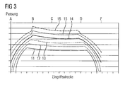
- FIG. 3 illustrates in which the pressure of the tooth flanks over the engagement distance for different loads is shown.
- the load-dependent migration of the tooth meshing bumps along the engagement path can be taken.
- the lowermost curve 11 shows the pressure above the engagement path for the lowest load and the uppermost curve 16 the pressure above the engagement path for the highest load.
- the applied load steadily increases from bottom to top.
- the comparison of the curves shows that with increasing load the total engagement time increases, while the duration between the starting point B and the end point D of the single engagement area decreases with increasing load. This change is detected via the vibration signal detected by structure-borne vibration transducer 4 and used according to the invention for determining the torque.
- the vibration signal is analyzed with regard to significant points and compared with reference values in order to identify possible damage. Damage due to deviations may be in the form of peaks or flanks in the vibration signal, or peaks or flanks in the signal may be shifted due to the damage.
- the consideration according to the invention of the torque acting on the transmission 1 in the context of the analysis of the signal for damage detection makes it possible to separate purely operational changes of the vibration signal from damage-related changes.
- the vibration signal is normalized to the torque according to the invention, for example, using known mathematical or function-dependent methods Find application.
- a vibration signal corresponding to the tooth engagement of a pair of gears 9, 10 of the second transmission stage 3 is detected and the vibration signal is compared with a calibration vibration signal. From the difference between the deviation of the two oscillation signals from the respective calibration oscillation signals, the torque acting on the transmission 1 is determined.
- the shaft, not shown, between the gears 9, 10 of the first and second gear stage is also deformed when a load is applied, and on the detection of the corresponding to the gear pairs vibration signals can also be taken into account for determining the torque and this deformation of the shaft.
- a vibration signal As a calibration vibration signal, a vibration signal is used, which corresponds to the vibrations caused by the rolling and pushing movement at a taking place under known load and speed meshing of the respective gear pair.
- the oscillation signal In order to be able to determine the change in the detected oscillation signal caused by an applied torque, the oscillation signal must be compared with a reference. Such a reference is created, for example, by taking a known vibration signal under known load and speed, which is associated with the meshing. It can also be a transfer function as part of a calibration measurement are determined, by means of which a discrete torque of the vibration signal is assigned a discrete.
- vibration signals can be detected at other points in the transmission 1 by means of not shown in the drawing structure-borne vibration sensor 4, which correspond to further arranged at different points in the gear 1 meshing. Then, the mean value of the deviation of the vibration signals from the calibration vibration signals is formed and the torque is determined from the mean value.
- a continuous monitoring and storage of the torque values determined in accordance with the invention takes place in the central control device 8 and an alarm signal is issued if one of the detected values lies outside a predefined permissible torque value range.
- the torque values are recorded spatially resolved and stored and the message includes the indication of the impermissible torque value and the location, at which point in the transmission 1 this was detected.
- individual torque values can also be compared with a mean value formed via various gearboxes in order to identify a local deviation from the mean value and to signal this by means of an alarm signal.
- a Fourier transformation of the detected vibration signal can also take place.
- a time-dependent vibration signal can be transformed into the frequency domain and it can be a frequency-dependent analysis of the signal.
- characteristic signal profiles such as peaks at discrete frequency values are then found and correlated with operational parameters such as the meshing basic frequency.
- the oscillation signal is represented in the frequency domain, then it can be filtered out of it in a predetermined frequency range lying part, in particular that part which extends by a predetermined frequency interval to the meshing basic frequency.
- the meshing basic frequency is determined using the tachometer 6, 7, wherein it is calculated in each case from the rotational speed and the known number of teeth of the gear 9, 10.
- the temperature of the transmission 1 and the device comprising the gear 1 are monitored by means of temperature sensors, not shown, and included in the evaluation of the vibration signal with regard to possible damage.
- the state of the gear oil, in particular the viscosity, the purity, the humidity and other characteristic values of the gear oil are also monitored and included in the evaluation. The recording of these additional operational parameters and their consideration in the analysis of the vibration signals allows the separation of operational and damage-related changes.
Landscapes
- Physics & Mathematics (AREA)
- Acoustics & Sound (AREA)
- General Physics & Mathematics (AREA)
- Testing Of Devices, Machine Parts, Or Other Structures Thereof (AREA)
Priority Applications (4)
| Application Number | Priority Date | Filing Date | Title |
|---|---|---|---|
| EP20110174330 EP2549257B1 (fr) | 2011-07-18 | 2011-07-18 | Procédé de détection de dommages sur des engrenages |
| ES11174330T ES2435843T3 (es) | 2011-07-18 | 2011-07-18 | Procedimiento para la detección de daños en engranajes |
| CN201210246687.8A CN102889986B (zh) | 2011-07-18 | 2012-07-16 | 用于识别传动装置上的故障的方法和装置 |
| US13/551,121 US9267864B2 (en) | 2011-07-18 | 2012-07-17 | Method for identifying damage on transmissions |
Applications Claiming Priority (1)
| Application Number | Priority Date | Filing Date | Title |
|---|---|---|---|
| EP20110174330 EP2549257B1 (fr) | 2011-07-18 | 2011-07-18 | Procédé de détection de dommages sur des engrenages |
Publications (2)
| Publication Number | Publication Date |
|---|---|
| EP2549257A1 true EP2549257A1 (fr) | 2013-01-23 |
| EP2549257B1 EP2549257B1 (fr) | 2013-10-30 |
Family
ID=44936148
Family Applications (1)
| Application Number | Title | Priority Date | Filing Date |
|---|---|---|---|
| EP20110174330 Not-in-force EP2549257B1 (fr) | 2011-07-18 | 2011-07-18 | Procédé de détection de dommages sur des engrenages |
Country Status (4)
| Country | Link |
|---|---|
| US (1) | US9267864B2 (fr) |
| EP (1) | EP2549257B1 (fr) |
| CN (1) | CN102889986B (fr) |
| ES (1) | ES2435843T3 (fr) |
Cited By (2)
| Publication number | Priority date | Publication date | Assignee | Title |
|---|---|---|---|---|
| CN103175687A (zh) * | 2013-03-07 | 2013-06-26 | 温州大学 | 一种活齿减速器故障定位方法 |
| WO2023117247A1 (fr) * | 2021-12-22 | 2023-06-29 | Robert Bosch Gmbh | Procédé de surveillance d'un état de fonctionnement ou d'un comportement de fonctionnement d'un dispositif d'entraînement électrique |
Families Citing this family (12)
| Publication number | Priority date | Publication date | Assignee | Title |
|---|---|---|---|---|
| US9482647B2 (en) | 2013-09-24 | 2016-11-01 | Sikorsky Aircraft Corporation | Gear fault detection |
| CN103604604A (zh) * | 2013-12-02 | 2014-02-26 | 清华大学 | 一种风力发电机齿轮传动箱故障模拟装置 |
| EP2910398B1 (fr) | 2014-02-21 | 2017-10-04 | Siemens Aktiengesellschaft | Machine à entraînement par chaîne |
| EP2975299A1 (fr) | 2014-07-18 | 2016-01-20 | Siemens Aktiengesellschaft | Palier à glissement pour support épicycloïdal |
| CN109073505A (zh) * | 2016-03-30 | 2018-12-21 | Ntn株式会社 | 齿轮装置的状态监视系统以及状态监视方法 |
| EP3284975B1 (fr) | 2016-08-19 | 2020-02-26 | Flender GmbH | Axe planetaire |
| DE102017111066A1 (de) * | 2017-05-22 | 2018-11-22 | Khs Gmbh | Verfahren zur Überwachung eines Prozesses |
| US10495693B2 (en) * | 2017-06-01 | 2019-12-03 | General Electric Company | Wind turbine fault detection using acoustic, vibration, and electrical signals |
| DE102019108278A1 (de) * | 2019-03-29 | 2020-10-01 | Liebherr-Components Biberach Gmbh | Vorrichtung zum Ermitteln des Ist-Zustands und/oder der Restlebensdauer einer Baumaschine |
| CN111222199B (zh) * | 2019-11-13 | 2022-06-21 | 中国汽车工程研究院股份有限公司 | 用户与试验场关联时关键指标选择与等效计算方法 |
| FR3110695B1 (fr) * | 2020-05-20 | 2022-05-13 | Airbus Helicopters | Système et procédé de surveillance de l’usure d’une roue libre et appareil associé |
| CN114812655A (zh) * | 2022-06-27 | 2022-07-29 | 中国电力科学研究院有限公司 | 一种轨道机车的位置传感器故障诊断方法及装置 |
Citations (3)
| Publication number | Priority date | Publication date | Assignee | Title |
|---|---|---|---|---|
| US4872337A (en) * | 1988-01-29 | 1989-10-10 | Watts Robert J | Nondestructive testing of gears |
| EP0889314A2 (fr) * | 1997-07-04 | 1999-01-07 | FINMECCANICA S.p.A. | Méthode de surveillance d'une transmission de véhicule équipée de capteurs d'accélération en particulier pour hélicoptère |
| DE19757317A1 (de) * | 1997-12-09 | 1999-07-15 | Daewoo Electronics Co Ltd | Überwachen des einwandfreien Arbeitens eines automatischen Getriebes |
Family Cites Families (14)
| Publication number | Priority date | Publication date | Assignee | Title |
|---|---|---|---|---|
| US3982419A (en) * | 1972-05-09 | 1976-09-28 | Standard Pressed Steel Co. | Apparatus for and method of determining rotational and linear stiffness |
| US4931949A (en) * | 1988-03-21 | 1990-06-05 | Monitoring Technology Corporation | Method and apparatus for detecting gear defects |
| JP2517792Y2 (ja) * | 1988-04-02 | 1996-11-20 | 株式会社明電舎 | 揺動形動力計のトルク検出装置 |
| JPH0733976B2 (ja) * | 1989-02-02 | 1995-04-12 | 富士電機株式会社 | 歯車の異常診断装置 |
| EP0399634A3 (fr) * | 1989-05-22 | 1991-03-20 | PLINT & PARTNERS LIMITED | Viscosimètre |
| US5067355A (en) * | 1990-07-13 | 1991-11-26 | General Electric Company | Shaft torque measurement |
| US5347857A (en) * | 1991-06-07 | 1994-09-20 | Caterpillar Inc. | Phase detection apparatus and method |
| DE19732124C2 (de) * | 1997-06-25 | 2003-04-17 | Kuesel Mailaender Katharina | Verfahren zum Prüfen eines Zahnrades sowie einer Zahnstange und Vorrichtung zum Prüfen eines Zahnrades |
| CN1221081A (zh) * | 1997-12-25 | 1999-06-30 | 大宇电子株式会社 | 控制自动变速器故障的方法及装置 |
| DE19835694A1 (de) * | 1998-08-07 | 2000-02-10 | Bosch Gmbh Robert | Sensoranordnung zur Erfassung eines Drehwinkels und/oder eines Drehmoments |
| WO2006043511A1 (fr) * | 2004-10-18 | 2006-04-27 | Nsk Ltd. | Systeme de diagnostic d’anomalie pour une machinerie |
| CN2809621Y (zh) * | 2005-04-08 | 2006-08-23 | 重庆工学院 | 锥齿轮传动质量智能检测系统 |
| TWM378377U (en) * | 2009-11-10 | 2010-04-11 | Legend Lifestyle Products Corp | Twisting force testing device |
| EP2431720B1 (fr) * | 2010-09-20 | 2013-01-16 | Eurocopter Deutschland GmbH | Procédé pour mesurer le couple et système de mesure du couple pour ledit procédé |
-
2011
- 2011-07-18 EP EP20110174330 patent/EP2549257B1/fr not_active Not-in-force
- 2011-07-18 ES ES11174330T patent/ES2435843T3/es active Active
-
2012
- 2012-07-16 CN CN201210246687.8A patent/CN102889986B/zh not_active Expired - Fee Related
- 2012-07-17 US US13/551,121 patent/US9267864B2/en not_active Expired - Fee Related
Patent Citations (3)
| Publication number | Priority date | Publication date | Assignee | Title |
|---|---|---|---|---|
| US4872337A (en) * | 1988-01-29 | 1989-10-10 | Watts Robert J | Nondestructive testing of gears |
| EP0889314A2 (fr) * | 1997-07-04 | 1999-01-07 | FINMECCANICA S.p.A. | Méthode de surveillance d'une transmission de véhicule équipée de capteurs d'accélération en particulier pour hélicoptère |
| DE19757317A1 (de) * | 1997-12-09 | 1999-07-15 | Daewoo Electronics Co Ltd | Überwachen des einwandfreien Arbeitens eines automatischen Getriebes |
Non-Patent Citations (2)
| Title |
|---|
| VON CJ CRAPTREE ET AL.: "Detecting Incipient Wind Turbine Gearbox Failure: The Signal Analysis Method for On-Line Condition Monitoring", EUROPEAN WIND ENERGY CONFERENCE, 2010 |
| VON CJ CRAPTREE ET AL.: "Detecting Incipient Wind Turbine Gearbox Failure: The Signal Analysis Method for On-Line Condition Monitoring", EUROPEAN WIND ENERGY CONFERENCE, 2010, XP002664789 * |
Cited By (2)
| Publication number | Priority date | Publication date | Assignee | Title |
|---|---|---|---|---|
| CN103175687A (zh) * | 2013-03-07 | 2013-06-26 | 温州大学 | 一种活齿减速器故障定位方法 |
| WO2023117247A1 (fr) * | 2021-12-22 | 2023-06-29 | Robert Bosch Gmbh | Procédé de surveillance d'un état de fonctionnement ou d'un comportement de fonctionnement d'un dispositif d'entraînement électrique |
Also Published As
| Publication number | Publication date |
|---|---|
| CN102889986B (zh) | 2016-10-26 |
| EP2549257B1 (fr) | 2013-10-30 |
| CN102889986A (zh) | 2013-01-23 |
| US20130180319A1 (en) | 2013-07-18 |
| US9267864B2 (en) | 2016-02-23 |
| ES2435843T3 (es) | 2013-12-23 |
Similar Documents
| Publication | Publication Date | Title |
|---|---|---|
| EP2549257B1 (fr) | Procédé de détection de dommages sur des engrenages | |
| DE102016105877B4 (de) | Verfahren und Vorrichtung zur Überwachung einer Maschine | |
| EP2937560B1 (fr) | Dispositif de diagnostic d'éoliennes pour composants du générateur | |
| EP1423827B1 (fr) | Dispositif et procede de detection precoce et de prediction de deteriorations d'unites | |
| EP2404059B1 (fr) | Procédé de surveillance d'éoliennes | |
| DE102011117468B4 (de) | Verfahren, Recheneinheit und Einrichtung zur Überwachung eines Antriebstrangs | |
| DE102011116961A1 (de) | Verfahren zur Bestimmung einer mechanischenBeschädigung eines Rotorblatts einerWindenergieanlage | |
| EP2169221B1 (fr) | Procédé de surveillance d'un engrenage d'éolienne | |
| DE102022128423B3 (de) | Verfahren und ein Antriebsmodul zur Detektion, Quantifikation und Kompensation einer Eingriffsstörung eines Spannungswellengetriebes | |
| DE102007003867A1 (de) | Verfahren und Vorrichtung zum Überwachen eines eine hochelastische Kupplung aufweisenden Antriebsstrangs | |
| EP2131178B1 (fr) | Procédé de diagnostic pour au moins un roulement à billes, en particulier pour un palier à billes oblique, système de diagnostic correspondant et utilisation d'un tel système de diagnostic | |
| DE102008049530A1 (de) | Verfahren zum Überwachen einer Triebstrangkomponente einer Windenergieanlage | |
| DE102008010466A1 (de) | Windenergieanlage mit Blatteinstellwinkelregler | |
| EP1892597A1 (fr) | Surveillance de machines et d'installations techniques | |
| EP2674581A1 (fr) | Composants de machine d'une chaîne cinématique ainsi que la méthode de conception et/ou de mettre en service et/ou d'opération d'une telle chaîne cinématique | |
| EP3100064B1 (fr) | Dispositif et procédé de détection de défauts dans des machines | |
| WO2020099336A1 (fr) | Dispositif et procédé de détermination de l'état d'au moins une paire de dents et/ou d'au moins une dent d'un système mécanique | |
| DE102010009941A1 (de) | Verfahren zum Überwachen von Windturbinen | |
| EP3120203B1 (fr) | Dispositif et procédé servant à identifier des anomalies dans des machines | |
| EP3783330A1 (fr) | Dispositif et procédé de surveillance d'au moins un palier lisse | |
| EP3388810B1 (fr) | Procédé et dispositif de détection de balancement | |
| DE102005048533A1 (de) | Verfahren und Anordnung zum Überwachen einer mechanischen Komponente, insbesondere eines Getriebes eines Fahrzeugs | |
| AT516959B1 (de) | Verfahren und Vorrichtung zur Zustandsüberwachung von Maschinen | |
| DE102017122089A1 (de) | Überwachungsanordnung und Verfahren zur Überwachung einer Maschine | |
| WO2022084058A1 (fr) | Procédé de fonctionnement d'une transmission de véhicule pour un véhicule à moteur et transmission de véhicule correspondante |
Legal Events
| Date | Code | Title | Description |
|---|---|---|---|
| PUAI | Public reference made under article 153(3) epc to a published international application that has entered the european phase |
Free format text: ORIGINAL CODE: 0009012 |
|
| 17P | Request for examination filed |
Effective date: 20111219 |
|
| AK | Designated contracting states |
Kind code of ref document: A1 Designated state(s): AL AT BE BG CH CY CZ DE DK EE ES FI FR GB GR HR HU IE IS IT LI LT LU LV MC MK MT NL NO PL PT RO RS SE SI SK SM TR |
|
| AX | Request for extension of the european patent |
Extension state: BA ME |
|
| RAP1 | Party data changed (applicant data changed or rights of an application transferred) |
Owner name: SIEMENS AKTIENGESELLSCHAFT |
|
| RIC1 | Information provided on ipc code assigned before grant |
Ipc: G01M 13/02 20060101AFI20130304BHEP |
|
| GRAP | Despatch of communication of intention to grant a patent |
Free format text: ORIGINAL CODE: EPIDOSNIGR1 |
|
| INTG | Intention to grant announced |
Effective date: 20130524 |
|
| GRAS | Grant fee paid |
Free format text: ORIGINAL CODE: EPIDOSNIGR3 |
|
| GRAA | (expected) grant |
Free format text: ORIGINAL CODE: 0009210 |
|
| AK | Designated contracting states |
Kind code of ref document: B1 Designated state(s): AL AT BE BG CH CY CZ DE DK EE ES FI FR GB GR HR HU IE IS IT LI LT LU LV MC MK MT NL NO PL PT RO RS SE SI SK SM TR |
|
| REG | Reference to a national code |
Ref country code: GB Ref legal event code: FG4D Free format text: NOT ENGLISH |
|
| REG | Reference to a national code |
Ref country code: CH Ref legal event code: EP |
|
| REG | Reference to a national code |
Ref country code: AT Ref legal event code: REF Ref document number: 638617 Country of ref document: AT Kind code of ref document: T Effective date: 20131115 |
|
| REG | Reference to a national code |
Ref country code: IE Ref legal event code: FG4D Free format text: LANGUAGE OF EP DOCUMENT: GERMAN |
|
| REG | Reference to a national code |
Ref country code: ES Ref legal event code: FG2A Ref document number: 2435843 Country of ref document: ES Kind code of ref document: T3 Effective date: 20131223 |
|
| REG | Reference to a national code |
Ref country code: DE Ref legal event code: R096 Ref document number: 502011001552 Country of ref document: DE Effective date: 20131224 |
|
| REG | Reference to a national code |
Ref country code: NL Ref legal event code: VDEP Effective date: 20131030 |
|
| REG | Reference to a national code |
Ref country code: LT Ref legal event code: MG4D |
|
| PG25 | Lapsed in a contracting state [announced via postgrant information from national office to epo] |
Ref country code: LT Free format text: LAPSE BECAUSE OF FAILURE TO SUBMIT A TRANSLATION OF THE DESCRIPTION OR TO PAY THE FEE WITHIN THE PRESCRIBED TIME-LIMIT Effective date: 20131030 Ref country code: IS Free format text: LAPSE BECAUSE OF FAILURE TO SUBMIT A TRANSLATION OF THE DESCRIPTION OR TO PAY THE FEE WITHIN THE PRESCRIBED TIME-LIMIT Effective date: 20140228 Ref country code: HR Free format text: LAPSE BECAUSE OF FAILURE TO SUBMIT A TRANSLATION OF THE DESCRIPTION OR TO PAY THE FEE WITHIN THE PRESCRIBED TIME-LIMIT Effective date: 20131030 Ref country code: NO Free format text: LAPSE BECAUSE OF FAILURE TO SUBMIT A TRANSLATION OF THE DESCRIPTION OR TO PAY THE FEE WITHIN THE PRESCRIBED TIME-LIMIT Effective date: 20140130 Ref country code: NL Free format text: LAPSE BECAUSE OF FAILURE TO SUBMIT A TRANSLATION OF THE DESCRIPTION OR TO PAY THE FEE WITHIN THE PRESCRIBED TIME-LIMIT Effective date: 20131030 Ref country code: SE Free format text: LAPSE BECAUSE OF FAILURE TO SUBMIT A TRANSLATION OF THE DESCRIPTION OR TO PAY THE FEE WITHIN THE PRESCRIBED TIME-LIMIT Effective date: 20131030 |
|
| PG25 | Lapsed in a contracting state [announced via postgrant information from national office to epo] |
Ref country code: CY Free format text: LAPSE BECAUSE OF FAILURE TO SUBMIT A TRANSLATION OF THE DESCRIPTION OR TO PAY THE FEE WITHIN THE PRESCRIBED TIME-LIMIT Effective date: 20131030 Ref country code: RS Free format text: LAPSE BECAUSE OF FAILURE TO SUBMIT A TRANSLATION OF THE DESCRIPTION OR TO PAY THE FEE WITHIN THE PRESCRIBED TIME-LIMIT Effective date: 20131030 Ref country code: LV Free format text: LAPSE BECAUSE OF FAILURE TO SUBMIT A TRANSLATION OF THE DESCRIPTION OR TO PAY THE FEE WITHIN THE PRESCRIBED TIME-LIMIT Effective date: 20131030 |
|
| PG25 | Lapsed in a contracting state [announced via postgrant information from national office to epo] |
Ref country code: PT Free format text: LAPSE BECAUSE OF FAILURE TO SUBMIT A TRANSLATION OF THE DESCRIPTION OR TO PAY THE FEE WITHIN THE PRESCRIBED TIME-LIMIT Effective date: 20140228 |
|
| PG25 | Lapsed in a contracting state [announced via postgrant information from national office to epo] |
Ref country code: EE Free format text: LAPSE BECAUSE OF FAILURE TO SUBMIT A TRANSLATION OF THE DESCRIPTION OR TO PAY THE FEE WITHIN THE PRESCRIBED TIME-LIMIT Effective date: 20131030 |
|
| REG | Reference to a national code |
Ref country code: DE Ref legal event code: R097 Ref document number: 502011001552 Country of ref document: DE |
|
| PG25 | Lapsed in a contracting state [announced via postgrant information from national office to epo] |
Ref country code: SK Free format text: LAPSE BECAUSE OF FAILURE TO SUBMIT A TRANSLATION OF THE DESCRIPTION OR TO PAY THE FEE WITHIN THE PRESCRIBED TIME-LIMIT Effective date: 20131030 Ref country code: PL Free format text: LAPSE BECAUSE OF FAILURE TO SUBMIT A TRANSLATION OF THE DESCRIPTION OR TO PAY THE FEE WITHIN THE PRESCRIBED TIME-LIMIT Effective date: 20131030 Ref country code: RO Free format text: LAPSE BECAUSE OF FAILURE TO SUBMIT A TRANSLATION OF THE DESCRIPTION OR TO PAY THE FEE WITHIN THE PRESCRIBED TIME-LIMIT Effective date: 20131030 Ref country code: CZ Free format text: LAPSE BECAUSE OF FAILURE TO SUBMIT A TRANSLATION OF THE DESCRIPTION OR TO PAY THE FEE WITHIN THE PRESCRIBED TIME-LIMIT Effective date: 20131030 |
|
| PLBE | No opposition filed within time limit |
Free format text: ORIGINAL CODE: 0009261 |
|
| STAA | Information on the status of an ep patent application or granted ep patent |
Free format text: STATUS: NO OPPOSITION FILED WITHIN TIME LIMIT |
|
| PG25 | Lapsed in a contracting state [announced via postgrant information from national office to epo] |
Ref country code: DK Free format text: LAPSE BECAUSE OF FAILURE TO SUBMIT A TRANSLATION OF THE DESCRIPTION OR TO PAY THE FEE WITHIN THE PRESCRIBED TIME-LIMIT Effective date: 20131030 |
|
| 26N | No opposition filed |
Effective date: 20140731 |
|
| REG | Reference to a national code |
Ref country code: DE Ref legal event code: R097 Ref document number: 502011001552 Country of ref document: DE Effective date: 20140731 |
|
| PG25 | Lapsed in a contracting state [announced via postgrant information from national office to epo] |
Ref country code: LU Free format text: LAPSE BECAUSE OF FAILURE TO SUBMIT A TRANSLATION OF THE DESCRIPTION OR TO PAY THE FEE WITHIN THE PRESCRIBED TIME-LIMIT Effective date: 20140718 Ref country code: SI Free format text: LAPSE BECAUSE OF FAILURE TO SUBMIT A TRANSLATION OF THE DESCRIPTION OR TO PAY THE FEE WITHIN THE PRESCRIBED TIME-LIMIT Effective date: 20131030 |
|
| REG | Reference to a national code |
Ref country code: CH Ref legal event code: PL |
|
| REG | Reference to a national code |
Ref country code: IE Ref legal event code: MM4A |
|
| PG25 | Lapsed in a contracting state [announced via postgrant information from national office to epo] |
Ref country code: CH Free format text: LAPSE BECAUSE OF NON-PAYMENT OF DUE FEES Effective date: 20140731 Ref country code: LI Free format text: LAPSE BECAUSE OF NON-PAYMENT OF DUE FEES Effective date: 20140731 |
|
| PG25 | Lapsed in a contracting state [announced via postgrant information from national office to epo] |
Ref country code: IE Free format text: LAPSE BECAUSE OF NON-PAYMENT OF DUE FEES Effective date: 20140718 |
|
| PG25 | Lapsed in a contracting state [announced via postgrant information from national office to epo] |
Ref country code: SM Free format text: LAPSE BECAUSE OF FAILURE TO SUBMIT A TRANSLATION OF THE DESCRIPTION OR TO PAY THE FEE WITHIN THE PRESCRIBED TIME-LIMIT Effective date: 20131030 Ref country code: MC Free format text: LAPSE BECAUSE OF FAILURE TO SUBMIT A TRANSLATION OF THE DESCRIPTION OR TO PAY THE FEE WITHIN THE PRESCRIBED TIME-LIMIT Effective date: 20131030 |
|
| PG25 | Lapsed in a contracting state [announced via postgrant information from national office to epo] |
Ref country code: GR Free format text: LAPSE BECAUSE OF FAILURE TO SUBMIT A TRANSLATION OF THE DESCRIPTION OR TO PAY THE FEE WITHIN THE PRESCRIBED TIME-LIMIT Effective date: 20140131 Ref country code: MT Free format text: LAPSE BECAUSE OF FAILURE TO SUBMIT A TRANSLATION OF THE DESCRIPTION OR TO PAY THE FEE WITHIN THE PRESCRIBED TIME-LIMIT Effective date: 20131030 Ref country code: BG Free format text: LAPSE BECAUSE OF FAILURE TO SUBMIT A TRANSLATION OF THE DESCRIPTION OR TO PAY THE FEE WITHIN THE PRESCRIBED TIME-LIMIT Effective date: 20131030 |
|
| REG | Reference to a national code |
Ref country code: FR Ref legal event code: PLFP Year of fee payment: 6 |
|
| PG25 | Lapsed in a contracting state [announced via postgrant information from national office to epo] |
Ref country code: TR Free format text: LAPSE BECAUSE OF FAILURE TO SUBMIT A TRANSLATION OF THE DESCRIPTION OR TO PAY THE FEE WITHIN THE PRESCRIBED TIME-LIMIT Effective date: 20131030 Ref country code: HU Free format text: LAPSE BECAUSE OF FAILURE TO SUBMIT A TRANSLATION OF THE DESCRIPTION OR TO PAY THE FEE WITHIN THE PRESCRIBED TIME-LIMIT; INVALID AB INITIO Effective date: 20110718 |
|
| PGFP | Annual fee paid to national office [announced via postgrant information from national office to epo] |
Ref country code: DE Payment date: 20160920 Year of fee payment: 6 |
|
| PGFP | Annual fee paid to national office [announced via postgrant information from national office to epo] |
Ref country code: ES Payment date: 20160826 Year of fee payment: 6 |
|
| REG | Reference to a national code |
Ref country code: FR Ref legal event code: PLFP Year of fee payment: 7 |
|
| REG | Reference to a national code |
Ref country code: AT Ref legal event code: MM01 Ref document number: 638617 Country of ref document: AT Kind code of ref document: T Effective date: 20160718 |
|
| PG25 | Lapsed in a contracting state [announced via postgrant information from national office to epo] |
Ref country code: AT Free format text: LAPSE BECAUSE OF NON-PAYMENT OF DUE FEES Effective date: 20160718 |
|
| PGFP | Annual fee paid to national office [announced via postgrant information from national office to epo] |
Ref country code: FR Payment date: 20170713 Year of fee payment: 7 Ref country code: FI Payment date: 20170720 Year of fee payment: 7 Ref country code: GB Payment date: 20170713 Year of fee payment: 7 Ref country code: IT Payment date: 20170726 Year of fee payment: 7 |
|
| PGFP | Annual fee paid to national office [announced via postgrant information from national office to epo] |
Ref country code: BE Payment date: 20170719 Year of fee payment: 7 |
|
| REG | Reference to a national code |
Ref country code: DE Ref legal event code: R119 Ref document number: 502011001552 Country of ref document: DE |
|
| PG25 | Lapsed in a contracting state [announced via postgrant information from national office to epo] |
Ref country code: DE Free format text: LAPSE BECAUSE OF NON-PAYMENT OF DUE FEES Effective date: 20180201 |
|
| PG25 | Lapsed in a contracting state [announced via postgrant information from national office to epo] |
Ref country code: MK Free format text: LAPSE BECAUSE OF FAILURE TO SUBMIT A TRANSLATION OF THE DESCRIPTION OR TO PAY THE FEE WITHIN THE PRESCRIBED TIME-LIMIT Effective date: 20131030 |
|
| REG | Reference to a national code |
Ref country code: ES Ref legal event code: FD2A Effective date: 20181026 |
|
| PG25 | Lapsed in a contracting state [announced via postgrant information from national office to epo] |
Ref country code: AL Free format text: LAPSE BECAUSE OF FAILURE TO SUBMIT A TRANSLATION OF THE DESCRIPTION OR TO PAY THE FEE WITHIN THE PRESCRIBED TIME-LIMIT Effective date: 20131030 |
|
| PG25 | Lapsed in a contracting state [announced via postgrant information from national office to epo] |
Ref country code: ES Free format text: LAPSE BECAUSE OF NON-PAYMENT OF DUE FEES Effective date: 20170719 |
|
| GBPC | Gb: european patent ceased through non-payment of renewal fee |
Effective date: 20180718 |
|
| REG | Reference to a national code |
Ref country code: BE Ref legal event code: MM Effective date: 20180731 |
|
| PG25 | Lapsed in a contracting state [announced via postgrant information from national office to epo] |
Ref country code: FI Free format text: LAPSE BECAUSE OF NON-PAYMENT OF DUE FEES Effective date: 20180718 Ref country code: GB Free format text: LAPSE BECAUSE OF NON-PAYMENT OF DUE FEES Effective date: 20180718 Ref country code: FR Free format text: LAPSE BECAUSE OF NON-PAYMENT OF DUE FEES Effective date: 20180731 |
|
| PG25 | Lapsed in a contracting state [announced via postgrant information from national office to epo] |
Ref country code: BE Free format text: LAPSE BECAUSE OF NON-PAYMENT OF DUE FEES Effective date: 20180731 |
|
| PG25 | Lapsed in a contracting state [announced via postgrant information from national office to epo] |
Ref country code: IT Free format text: LAPSE BECAUSE OF NON-PAYMENT OF DUE FEES Effective date: 20180718 |