EP2551415A2 - Composant d'évacuation - Google Patents
Composant d'évacuation Download PDFInfo
- Publication number
- EP2551415A2 EP2551415A2 EP20110195624 EP11195624A EP2551415A2 EP 2551415 A2 EP2551415 A2 EP 2551415A2 EP 20110195624 EP20110195624 EP 20110195624 EP 11195624 A EP11195624 A EP 11195624A EP 2551415 A2 EP2551415 A2 EP 2551415A2
- Authority
- EP
- European Patent Office
- Prior art keywords
- drain
- drain component
- component according
- floor structure
- flocking
- Prior art date
- Legal status (The legal status is an assumption and is not a legal conclusion. Google has not performed a legal analysis and makes no representation as to the accuracy of the status listed.)
- Ceased
Links
Images


Classifications
-
- E—FIXED CONSTRUCTIONS
- E03—WATER SUPPLY; SEWERAGE
- E03F—SEWERS; CESSPOOLS
- E03F5/00—Sewerage structures
- E03F5/04—Gullies inlets, road sinks, floor drains with or without odour seals or sediment traps
- E03F5/0407—Floor drains for indoor use
- E03F5/0409—Devices for preventing seepage around the floor drain
-
- Y—GENERAL TAGGING OF NEW TECHNOLOGICAL DEVELOPMENTS; GENERAL TAGGING OF CROSS-SECTIONAL TECHNOLOGIES SPANNING OVER SEVERAL SECTIONS OF THE IPC; TECHNICAL SUBJECTS COVERED BY FORMER USPC CROSS-REFERENCE ART COLLECTIONS [XRACs] AND DIGESTS
- Y10—TECHNICAL SUBJECTS COVERED BY FORMER USPC
- Y10T—TECHNICAL SUBJECTS COVERED BY FORMER US CLASSIFICATION
- Y10T137/00—Fluid handling
- Y10T137/6851—With casing, support, protector or static constructional installations
- Y10T137/6966—Static constructional installations
- Y10T137/6969—Buildings
- Y10T137/6988—Floor installation
Definitions
- the present invention relates to a drain component according to the preamble of claim 1.
- Such a drain component may be formed, for example, as a drain pot or Aufstockteil for a drain device and at least partially made of plastic.
- a drainage part comprises a flange which rests on a layer of the floor structure, for example on a screed, and serves as a base for a composite seal and tiles arranged thereon.
- the flange resting loosely on the layer of the floor structure deforms under load. This can lead to cracks in the tile adhesive and the composite seal. As a result, leaks can occur.
- the problem underlying the present invention is the provision of a drain component of the type mentioned, which is resistant to deformation in the installed state and / or has better adhesion to one or more layers of the floor structure.
- connecting means for the connection with one or more layers of the floor structure are arranged on the surface of the drain component. This can be achieved that with the surface of the casserole component provided with such connection means enters into a fixed connection with one or more layers of the floor structure. For example, in the arrangement of the connecting means on the underside of a flange then a vibration excitation of the flange is no longer possible or at least less likely.
- the connecting means are formed as flocking or include flocking.
- the flocking can be arranged over the entire surface or in sections on the surface of the drain component.
- the flocking may include synthetic fibers such as polyamide fibers or polyester fibers, or natural fibers such as flax or hemp. With such materials flocking can be made, the very effective adhesion bridges to the surrounding layers of the floor structure, such as a screed and / or composite seal and / or tile adhesive and / or a concrete section and / or a wood portion of the floor structure form.
- the connecting means are formed as a tile or comprise a tile.
- the fleece can be arranged over the entire surface or in sections on the surface of the drain component.
- the fleece and / or the fibers or flakes used as flocking may be injected or injected at least in sections on or into the surface of the drain component.
- the fleece or the flock adhere very well to the drain component and on the other hand, a very effective adhesion bridge to the surrounding layers of the floor structure, such as a screed and / or a composite seal and / or to form a tile adhesive and / or to a concrete section and / or to a wood portion of the floor structure.
- the flocking and / or the fleece are designed in such a way that they can enter into a cohesive connection with one or more layers of the floor structure. In this way, a firm connection with the or the corresponding layers of the floor structure.
- the connecting means comprise at least one connecting element, which protrudes in the installed position of the surface of the drain component at least partially or partially away.
- a gap may be present in sections between a section of the at least one connecting element and the surface of the drain component.
- the at least one connecting element can be designed in such a way that it can form a positive connection with one or more layers of the floor structure. The at least one connecting element can therefore likewise bring about a fixed connection between a part of the surface of the drain component and one or more layers of the floor structure.
- the connecting element may have an extension in the direction away from the drain component between 0.1 mm to 150 mm.
- an extension between 3 mm and 30 mm can be provided.
- the connecting element may for example be hook-shaped or mushroom-shaped.
- the at least one connecting element is formed integrally with the drain component or is connected as a separate part with the drain component, in particular detachably, for example via a screw or clips or locking connection is connected. It is quite possible to provide both embodiments of the connecting element at the same time on a drain component.
- the one-piece design allows for a more rational production, whereas the design allows a variable attachment as needed as a separate detachable part.
- the connecting element projects in the installed position from the lower side of a flange at least partially or partially downwards.
- the at least one connecting element can be designed such that it can form a positive connection with a screed.
- the drainage member comprises a tubular or an elongated groove-shaped portion through which wastewater can pass, and a flange which extends outwardly from the tubular or elongated groove-shaped portion, wherein on the flange the connecting means for the connection are arranged with one or more layers of the floor structure.
- the connecting means may be arranged on the lower side of the flange in the installed position and / or on the upper side of the flange in the installed position.
- the drain component is designed as an attachment part for a drainage device.
- the drain component is part of a drain device, wherein in particular the tubular or the elongated channel-shaped portion is part of a drain pot.
- both the drain part designed as an overflow component and the drainage element designed as a drainage component have a cylindrical or groove-like shape.
- the drain or the inlet opening can thus be formed in a punctiform or rotationally symmetrical, as well as linear or elongated channel-like.
- the in the Fig. 1 to Fig. 3 Pictured first embodiment of a drain component according to the invention is designed as an attachment part.
- the drain component comprises a tubular portion 1, of which a flange 2 protrudes radially outwardly in the installed position above.
- the tubular portion 1 can be inserted, for example, in a drain pot of a drain device.
- the flange 2 can as Pad for a composite seal and applied tiles serve.
- the tubular portion 1 has a central opening 3 for the passage of wastewater.
- the flange 2 has on its upper side in the installed position 4, a tile 5, which is molded or injected on or in the mounting position in the upper side 4 of the flange 2 (see Fig. 3 ).
- the tile 5 can serve, for example, as a bonding layer for a composite seal or as a bonding bridge for tile adhesive.
- the connecting elements 7 On the mounting side in the lower side 6 of the flange 2, a plurality of connecting elements 7 are arranged (see Fig. 1 to Fig. 3 ).
- the connecting elements 7 have a first cylindrical portion 8 extending downward from the lower side 6 and an adjoining second cylindrical portion 9 having a diameter which is larger than the diameter of the first portion 8. This results between the second portion 9 and the lower side 6 of the flange 2, a gap 10 and an undercut.
- this gap 10 for example, a screed penetrate during its creation, so that there is a positive connection between the screed and the connecting elements 7.
- one, several or all connecting elements 7 have a different cross-sectional shape such as a triangular, a quadrangular, a polygonal cross-sectional shape or the shape of a drop or that one, several or all connecting elements as parallel to the lower side 6 aligned webs are formed.
- the connecting elements 7 are an integral part of the drain component. So they are injected for example in one embodiment as an injection molded part.
- the connecting elements 7 are releasably connected by screws 12 with the drain component. Furthermore, the in Fig. 4 illustrated connecting elements 7 hook-shaped, whereas in the Fig. 1 to Fig. 3 pictured first embodiment has a mushroom shape rather. However, it is quite possible to provide in the first embodiment hook-shaped, integrally connected to the drain component connecting elements 7 and releasably attachable in the second embodiment, mushroom-shaped connecting elements 7.
- the connecting elements 7 may have an extension in the direction away from the drain component direction between 0.1 mm to 150 mm.
- an extension between 3 mm and 30 mm can be provided.
- connecting elements 7 can also be arranged on the upper side 4 in the installation position of the flange 2.
- connecting elements can also be provided at any point in the case of a pot-shaped or differently shaped drain component.
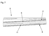
- the illustrated third embodiment differs from the first two embodiments in that no individual connecting elements 7 are provided, but that a fleece 11 is arranged on the lower side 6.
- the fleece 11 can on or in the installation position lower side 6 of Flange 2 be injected or injected (see Fig. 7 ).
- the fleece 11 is designed such that it can enter into a material connection with the screed or other layers of the floor structure.
- the flocking may include synthetic fibers such as polyamide fibers or polyester fibers, or natural fibers such as flax or hemp.
- Such flocking can be produced, for example, by pretreating the surface of the drainage component to be flocked and subsequently applying it with an adhesive. Thereafter, chemically suitable prepared flakes or fibers can be applied to the adhesive layer. After drying of the drain component or the flocking applied thereto may also as effective adhesion bridge to the surrounding layers of the soil structure, such as a screed and / or composite seal and / or tile adhesive and / or concrete section and / or serve a wood section of the floor structure.
- the flakes or fibers are injected or injected directly into or onto the plastic of the surface of the drain component to be flocked.
- the fleece 5, 11 and / or the flocking are not arranged over the entire surface but only in sections on the surface of the drain component, in particular on the lower side 6 and / or the upper side 4 of the flange 2.
- the flocking or the fleece 5, 11 may be interrupted on the lower side 6 and / or the upper side 4 of the flange 2 by at least one non-flocked, or not provided with a fleece, surface, such as a circular ring surface.
- these annular surfaces could also be interconnected by non-flocked, or not provided with a tile, radially extending channels.
- At least one unflocked, or not provided with a fleece, radially inwardly directed channel extends to the drain opening.
- non-flocked, or not provided with a fleece surface geometries which are connected or separate from each other, would be conceivable.
- segment-like, in particular circular segment-like, surfaces could be provided with a flocking or a fleece, wherein every second segment is not provided with a fleece or a flocking.
- the surface provided with connecting means according to the invention can thus be part of a gutter-shaped floor drain.
Landscapes
- Health & Medical Sciences (AREA)
- Life Sciences & Earth Sciences (AREA)
- Engineering & Computer Science (AREA)
- Hydrology & Water Resources (AREA)
- Public Health (AREA)
- Water Supply & Treatment (AREA)
- Floor Finish (AREA)
- Passenger Equipment (AREA)
Priority Applications (4)
| Application Number | Priority Date | Filing Date | Title |
|---|---|---|---|
| EP20110195624 EP2551415A3 (fr) | 2011-07-26 | 2011-12-23 | Composant d'évacuation |
| DE201220002808 DE202012002808U1 (de) | 2011-07-26 | 2012-03-17 | Ablaufbauteil |
| CA2780609A CA2780609A1 (fr) | 2011-07-26 | 2012-06-21 | Composante de drain |
| US13/557,680 US20130025708A1 (en) | 2011-07-26 | 2012-07-25 | Drain component |
Applications Claiming Priority (3)
| Application Number | Priority Date | Filing Date | Title |
|---|---|---|---|
| DE102011108540A DE102011108540A1 (de) | 2011-07-26 | 2011-07-26 | Haftungsoptimiertes Aufstockelement |
| EP11190820 | 2011-11-25 | ||
| EP20110195624 EP2551415A3 (fr) | 2011-07-26 | 2011-12-23 | Composant d'évacuation |
Publications (2)
| Publication Number | Publication Date |
|---|---|
| EP2551415A2 true EP2551415A2 (fr) | 2013-01-30 |
| EP2551415A3 EP2551415A3 (fr) | 2013-03-06 |
Family
ID=45421977
Family Applications (1)
| Application Number | Title | Priority Date | Filing Date |
|---|---|---|---|
| EP20110195624 Ceased EP2551415A3 (fr) | 2011-07-26 | 2011-12-23 | Composant d'évacuation |
Country Status (3)
| Country | Link |
|---|---|
| US (1) | US20130025708A1 (fr) |
| EP (1) | EP2551415A3 (fr) |
| CA (1) | CA2780609A1 (fr) |
Cited By (1)
| Publication number | Priority date | Publication date | Assignee | Title |
|---|---|---|---|---|
| EP2818602B1 (fr) * | 2013-06-26 | 2017-05-31 | Geberit International AG | Agencement d'évacuation |
Families Citing this family (2)
| Publication number | Priority date | Publication date | Assignee | Title |
|---|---|---|---|---|
| US20200080292A1 (en) * | 2018-09-10 | 2020-03-12 | Schluter Systems, L.P. | Low-profile Drain |
| US11209108B2 (en) | 2018-09-10 | 2021-12-28 | Schluter Systems L.P. | Drain coupler with compressible seal |
Family Cites Families (11)
| Publication number | Priority date | Publication date | Assignee | Title |
|---|---|---|---|---|
| USRE24478E (en) * | 1954-02-01 | 1958-05-27 | Flexible gaskets | |
| US2898129A (en) * | 1956-05-23 | 1959-08-04 | Lulu E Sisk | Clamping device for floor drains with removable clamps |
| US4146939A (en) * | 1977-12-02 | 1979-04-03 | Izzi Lewis B | Drain fitting for pre-formed or pre-assembled showers, etc. |
| DE8713353U1 (de) * | 1987-10-05 | 1988-01-07 | Hauraton Betonwarenfabrik GmbH & Co KG, 7550 Rastatt | Aus verbundenen Teilstücken zusammengesetzte Ablaufrinne |
| SE9300711L (sv) * | 1993-03-04 | 1994-08-15 | Lars Croon | Anordning vid golvbrunn |
| WO2007016672A2 (fr) * | 2005-08-02 | 2007-02-08 | Degooyer Lonnie C | Adapateur d’avaloir de douche |
| US7992236B2 (en) * | 2006-03-01 | 2011-08-09 | Schluter Systems, L.P. | Mock shower drain and associated methods |
| JP5010642B2 (ja) * | 2008-06-30 | 2012-08-29 | 日東電工株式会社 | ガスケット材 |
| DE102008038404B4 (de) * | 2008-08-19 | 2022-01-13 | Tece Gmbh | Einbauverfahren für ein Bodenablaufsystem und Bodenablaufsystem zu dessen Durchführung |
| US8239974B2 (en) * | 2008-12-29 | 2012-08-14 | Josef Erlebach | Elongated shower drain |
| DE202009006564U1 (de) * | 2009-05-07 | 2012-02-27 | Hydrophon Kunststofftechnik Gmbh | Dichtungssystem für Bodenablauf-Rinnen |
-
2011
- 2011-12-23 EP EP20110195624 patent/EP2551415A3/fr not_active Ceased
-
2012
- 2012-06-21 CA CA2780609A patent/CA2780609A1/fr not_active Abandoned
- 2012-07-25 US US13/557,680 patent/US20130025708A1/en not_active Abandoned
Non-Patent Citations (1)
| Title |
|---|
| None * |
Cited By (1)
| Publication number | Priority date | Publication date | Assignee | Title |
|---|---|---|---|---|
| EP2818602B1 (fr) * | 2013-06-26 | 2017-05-31 | Geberit International AG | Agencement d'évacuation |
Also Published As
| Publication number | Publication date |
|---|---|
| US20130025708A1 (en) | 2013-01-31 |
| CA2780609A1 (fr) | 2013-01-26 |
| EP2551415A3 (fr) | 2013-03-06 |
Similar Documents
| Publication | Publication Date | Title |
|---|---|---|
| EP2098651A2 (fr) | Profilé de remplissage de joint et son procédé de fabrication | |
| EP1532331A1 (fr) | Procede pour poser des tirants sur des appareils porteurs et dispositif pour realiser ce procede | |
| EP2551415A2 (fr) | Composant d'évacuation | |
| DE68904412T2 (de) | Vorrichtung zum plazieren und befestigen von teilen auf einem filterboden, wobei die teile den durchgang von fluiden durch diesen filterboden sicherstellen. | |
| EP3190244B1 (fr) | Douille filetée d'ancrage d'éléments de construction dans un ouvrage en béton et entretoise tubulaire | |
| EP1370774B1 (fr) | Douille d'ancrage pour scellement par injection | |
| EP2431533A2 (fr) | Dispositif de levage de couvercle | |
| DE202012002808U1 (de) | Ablaufbauteil | |
| EP1762668B1 (fr) | Matériau de drainage pour le drainage de couvertures de marches d'escaliers | |
| EP3064650B1 (fr) | Système de fermeture de puits et procédé de montage | |
| WO2024074994A1 (fr) | Procédé de fabrication d'une dalle en béton à partir de béton précontraint | |
| DE102011108540A1 (de) | Haftungsoptimiertes Aufstockelement | |
| EP4282606B1 (fr) | Élément fonctionnel pour la construction | |
| EP3263787B1 (fr) | Élément structural en béton préfabriqué, en particulier plaque en béton préfabriqué, ancrage de transport pour un tel élément en béton | |
| DE102020201686A1 (de) | Fugenprofil | |
| EP1659231B1 (fr) | Dispositif de fixation pour une ancre pourvue d'une tête d'ancrage | |
| EP1672141A1 (fr) | Support de plaque de coffrage | |
| DE202013006822U1 (de) | Abstandhalter für mit einem Basismaterial herzustellende Bauteile mit textilen Bewehrungslagen | |
| EP2806083A1 (fr) | Dispositif de fixation de plaques de matière synthétique sur des constructions ou des éléments de construction et procédé d'habillage d'éléments de construction ou de constructions avec des plaques de matière synthétique | |
| EP1233117B1 (fr) | Dispositif d'étanchéité pour une bouche d'évacuation d'eau | |
| DE102008019799A1 (de) | Kanalbausystem wie zum Beispiel ein rohrförmiges Element zur Herstellung von Leitungen, Schächten, Formstücken und dergleichen | |
| DE3047116A1 (de) | Abstandshalter fuer stahlbetonbewehrungen sowie verfahren zur herstellung solcher abstandshalter | |
| EP2618008B1 (fr) | Moyen de fixation pour la fixation d'une poutre en bois et d'une plaque en béton ensemble, procédé de fixation d'une poutre en bois et d'une plaque en béton ensemble ainsi que composant sous la forme d'une plaque en béton reliée à au moins une poutre en bois | |
| EP2687136A1 (fr) | Élément de douche | |
| AT524807A2 (de) | Balkon- oder Terrassenelement mit einer Entwässerungseinrichtung, Entwässerungseinrichtung für ein solches Balkon- oder Terrassenelement sowie Herstellungsverfahren |
Legal Events
| Date | Code | Title | Description |
|---|---|---|---|
| PUAI | Public reference made under article 153(3) epc to a published international application that has entered the european phase |
Free format text: ORIGINAL CODE: 0009012 |
|
| AK | Designated contracting states |
Kind code of ref document: A2 Designated state(s): AL AT BE BG CH CY CZ DE DK EE ES FI FR GB GR HR HU IE IS IT LI LT LU LV MC MK MT NL NO PL PT RO RS SE SI SK SM TR |
|
| AX | Request for extension of the european patent |
Extension state: BA ME |
|
| PUAL | Search report despatched |
Free format text: ORIGINAL CODE: 0009013 |
|
| AK | Designated contracting states |
Kind code of ref document: A3 Designated state(s): AL AT BE BG CH CY CZ DE DK EE ES FI FR GB GR HR HU IE IS IT LI LT LU LV MC MK MT NL NO PL PT RO RS SE SI SK SM TR |
|
| AX | Request for extension of the european patent |
Extension state: BA ME |
|
| RIC1 | Information provided on ipc code assigned before grant |
Ipc: E03F 5/04 20060101AFI20130128BHEP |
|
| 17P | Request for examination filed |
Effective date: 20130906 |
|
| RAX | Requested extension states of the european patent have changed |
Extension state: BA Payment date: 20130906 Extension state: ME Payment date: 20130906 |
|
| RBV | Designated contracting states (corrected) |
Designated state(s): AL AT BE BG CH CY CZ DE DK EE ES FI FR GB GR HR HU IE IS IT LI LT LU LV MC MK MT NL NO PL PT RO RS SE SI SK SM TR |
|
| 17Q | First examination report despatched |
Effective date: 20150429 |
|
| STAA | Information on the status of an ep patent application or granted ep patent |
Free format text: STATUS: THE APPLICATION HAS BEEN REFUSED |
|
| 18R | Application refused |
Effective date: 20180225 |