EP2553343B2 - Porte de four et procédé pour fixer un habillage de porte à une telle porte de four - Google Patents
Porte de four et procédé pour fixer un habillage de porte à une telle porte de four Download PDFInfo
- Publication number
- EP2553343B2 EP2553343B2 EP11711785.3A EP11711785A EP2553343B2 EP 2553343 B2 EP2553343 B2 EP 2553343B2 EP 11711785 A EP11711785 A EP 11711785A EP 2553343 B2 EP2553343 B2 EP 2553343B2
- Authority
- EP
- European Patent Office
- Prior art keywords
- door
- covering part
- oven
- projection
- snap
- Prior art date
- Legal status (The legal status is an assumption and is not a legal conclusion. Google has not performed a legal analysis and makes no representation as to the accuracy of the status listed.)
- Active
Links
Images

Classifications
-
- F—MECHANICAL ENGINEERING; LIGHTING; HEATING; WEAPONS; BLASTING
- F24—HEATING; RANGES; VENTILATING
- F24C—DOMESTIC STOVES OR RANGES ; DETAILS OF DOMESTIC STOVES OR RANGES, OF GENERAL APPLICATION
- F24C15/00—Details
- F24C15/02—Doors specially adapted for stoves or ranges
- F24C15/04—Doors specially adapted for stoves or ranges with transparent panels
Definitions
- the invention relates to an oven door. Furthermore, the invention is based on a method for fastening a door cover part to such an oven door according to the preamble of claim 10.
- oven doors are used in a front arrangement. These are usually rotatably mounted on the appliance housing, with a large number of baking and roasting ovens being mounted on the lower edge of the oven door, so that when the oven door is opened, a pivoting movement occurs and this moves from a vertical arrangement when it is closed to a horizontal arrangement when it is open state passes.
- baking and roasting ovens are also known in which the door hinge is arranged in the area of a side edge of the oven door, so that the door executes a rotary movement about a horizontal axis when it is opened and closed.
- Oven doors of this type with a lateral hinge are used in particular in so-called double roasting ovens, i.e. those devices which comprise two oven muffles which are separate from one another and arranged one on top of the other.
- Such oven doors generally have a vertically arranged door panel, with a door glass being used in particular for this purpose.
- This door panel or this door glass regularly has two vertically arranged door frame or door pillar parts, which are arranged on the door panel in its right and left side areas or edges, in particular by means of an adhesive connection.
- a door covering part which covers at least the door panel at its upper edge, but in particular also the upper end faces of the vertically arranged door frame or door pillar parts from above.
- Such an oven door is in particular from EP 0 811 806 B2 famous.
- This document discloses an oven door of the aforementioned type, in which the door cover part is designed in a one-piece design with an actuating handle and this combination part is placed from above onto the door panel and the door frame parts or door pillar parts and is either screwed or latched to them.
- EP 1 867 927 A2 an oven door with a door cover part, wherein the door cover part is fastened to a door frame part or door pillar part by means of a snap connection.
- the door cover part comprises a spike or projection which is arranged on a first side area of the door cover part, with this spike or projection being designed in such a way that it fits into a corresponding recess which is on the first Door frame part or door pillar part is arranged, can engage.
- the means for producing the snap connection is also provided in the side area of the door covering part facing away from the pin or projection, with this means being designed in such a way that it engages in a recess on the second door frame part or door pillar part by means of a snap connection.
- a door covering part is created that can be built into any oven door, regardless of whether it is a door that can be pivoted about a horizontal axis or a door that can be pivoted about a vertical axis.
- the oven door can also be in the installed state on the device.
- the hinge area for installing the door covering part is not directly accessible from above.
- the mandrel or projection has an insertion bevel or point. This can also be an oblique flattening in the lower area of the mandrel or projection.
- the snap means which is arranged at the end region of the door covering part, which lies opposite the end region with the spike or projection, is preferably rigidly connected to the door covering part end region, in particular to a side wall located there.
- the snapping means and/or the side wall is/are designed flexibly in such a way that the snapping means and/or the side wall deviate from the rest position when snapping in can or can.
- the more flexible configuration is preferably directed towards the side wall. In this case, namely a slight expansion of mitabdeckmaschines, z. B.
- the snap means can be disengaged from the recess on the door frame or door pillar part.
- the snap-in means which is rigidly connected to the side wall of the door cover part, follows the evasive movement that follows the manual pressure, so that the snap-in means, in particular a snap-in hook, emerges from the recess.
- a support point is provided on the underside in the first side area of the door cover part.
- this bearing point interacts with the door frame or door pillar part in such a way that when the side area on which the snap-in means is located is pressed down, the mandrel or projection is moved upwards according to the principle of a seesaw, and at the end of the installation process, i . H. ie in the installed state, the upper side of the mandrel or projection is supported on an upper edge of the recess into which the mandrel or projection is inserted.
- the mandrel or projection is therefore under tension when installed, caused by the interaction of the recess and mandrel or projection at one end and snapped-in snap means at the other end, both of which hold the door covering part down, and the bearing point, which introduces a force component upwards at this point.
- This pretension ensures that the door cover part is coupled to the oven door without play, so that this part does not rattle when the oven is in use.
- the door covering part In the direction parallel to the upper edge of the door panel, the door covering part is held in position in particular by the latched snap-in means and by a positioning tongue which is supported on a stop wall or edge on the second door frame part or door pillar part. As already described above, it can be fixed in the direction parallel to the door panel by the pin or projection supported on the upper edge of the recess and by the engaged snap-in means. Finally, it can also be provided that the door covering part is held in the direction perpendicular to the upper edge of the door panel and perpendicular to the surface of the door panel by the spike or projection engaging in the recess and the second stop wall or edge arranged on the second door frame or door pillar part supporting positioning tongue is positioned. In realizing all of the aforementioned positioning measures, the door cover part is restricted in all three degrees of freedom and is therefore securely connected to the oven door.
- a pin or projection arranged on a first side region of the door cover part is inserted into a recess arranged on the first vertical door frame or door pillar part by parallel displacement relative to the upper edge of the door panel, the door cover part being under a pointed Angle aligned to the upper edge of the door panel and attached to the recess, and in that the door cover part is lowered after the insertion of the mandrel or projection by a rotary movement about a support point in the area of the first end section of the door cover part while reducing the acute angle and finally with help is snapped onto the second vertical door frame or door pillar part by snap means which are arranged on the second end region of the door covering part remote from the spike or projection.
- the mandrel or projection is preferably introduced into the recess at an angle in a range of approximately 5 to approximately 50 degrees between the upper edge of the door panel and the door covering part.
- the mandrel or projection inserted into the recess is preferably moved upwards during the installation process with final snapping, due to the rotary movement about the support point, and it is supported against the upper edge of the recess when the door cover part is installed.
- Removal of the door cover member may be accomplished by initially disengaging the snap means and then performing the removal movement in the reverse order of the installation movement.
- the snap means is rigidly connected to a side wall of the door cover part and can be disengaged by manual pressure on the side wall.
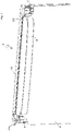
- An oven door 1 for closing a baking or roasting chamber of an oven comprises an outwardly directed front pane 3 and an inner pane 15 which adjoins the baking or roasting chamber.
- a door handle 5 is provided to open the door 1 .
- a left 7 and a right 9 door pillar are glued to the side edges of the windscreen 3 .
- the door is a door that can be rotated about a vertical axis, so that for this purpose door hinges 11 are arranged on the top and bottom of the left-hand door pillar 7 .
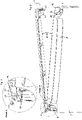
- the oven door 1 also has a door cover 13 which covers the front pane 3 and inner pane 15 at their upper edges. While figure 1 showing the door cover 13 installed is in figure 2 an arrangement of the door cover 13 reproduced as it is at the beginning of an installation process.
- the left door pillar comprises a metal hinge arm 17 which is covered by a door pillar cover 19.
- the hinge arm 17 is U-shaped in its central region, with only the central part of this U-shape remaining at least at its upper end.
- the door cover 13 is coupled in this end area of the hinge arm 17 .
- the end of the hinge arm has U-shaped recesses 21 on its side edges.
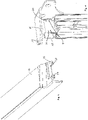
- FIG. 4 and 5 each shown an individual representation of the hinge arm end and the associated end of the door cover 13. Like in particular figure 5 As can be seen, a mandrel 23 and a projection 25 are arranged at the end of the door cover 13 and are accommodated by the two recesses 21 when the door cover 13 is installed.
- the door cover 13 is installed by initially threading the mandrel 23 and the projection 25 into the two recesses 21 .
- the door cover 13 is brought up to the hinge arm 17 at an acute angle of about 10 degrees in a horizontal movement parallel to the upper edges of the front pane 3 and inner pane 15 until the mandrel 23 and projection 25 are inserted into the recesses 21 .
- the mandrel 23 has an insertion bevel 27 on the underside. Following this insertion process, the door cover 13 is pressed down at its right end until it comes to rest on the top edges of the panes.
- the door cover 13 rotates about its bearing point 29 at its left end. Since the support point 29 is located between the mandrel 23 or projection 25 and the right-hand end of the door cover 13, the mandrel 23 and the projection 25 are simultaneously moved upwards while the right-hand end of the door cover 13 is being pressed down until their upper edges touch the respective upper edges of the recesses 21 concerns come.
- mandrel 23 and projection 25 rest against the upper edges 31 of the recesses 21 without play, with the upper edges 31 of the recesses 21 advantageously exerting pressure on the mandrel 23 and projection 25 so that they are under tension.
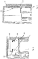
- a means 33 is provided in the form of a snap hook, which engages in a rear handle 35 on the right door pillar 9 .
- the door cover 13 is securely fastened to the oven door 1 with no play.
- a vertical tongue 37 is arranged on the door cover 13 at its right end as a stop part.
- This tongue 39 strikes a stop wall 43 (see in particular figure 7 ) and is delimited in its opposite direction by the windshield 3.
- the stop wall 43 is curved in the upper area in order to provide an insertion bevel.
- tongue 37 is also provided to limit movement in a direction parallel to the upper edge of front pane 3 and inner pane 15 .
- a stop edge 39 on the right-hand door pillar which corresponds to the side edge of tongue 37 .
- Another insertion bevel 41 is provided on the tongue 37 so that the tongue 37 does not get caught on the stop edge 39 when the door cover 13 is installed.
Landscapes
- Engineering & Computer Science (AREA)
- Chemical & Material Sciences (AREA)
- Combustion & Propulsion (AREA)
- Mechanical Engineering (AREA)
- General Engineering & Computer Science (AREA)
- Electric Ovens (AREA)
Claims (14)
- Porte de four (1), en particulier avec une charnière de porte (11) disposée latéralement, comprenant :(a) au moins un panneau de porte (3, 15) disposé verticalement dans un état fermé de la porte de four (1), en particulier un verre de porte,(b) une première et une deuxième partie de cadre de porte ou partie de colonne de porte (7, 9) disposées verticalement dans l'état fermé de la porte de four (1), qui sont disposées sur le panneau de porte (3) dans ses régions latérales ou ses arêtes latérales droites et gauches dans l'état fermé de la porte de four (1) ; et(c) une partie de recouvrement de porte (13) qui recouvre au moins le panneau de porte (3, 15) dans l'état fermé de la porte de four (1) par le dessus au niveau de son arête supérieure et comprend un moyen (33) pour réaliser une connexion par encliquetage,
caractérisée en ce que la partie de recouvrement de porte (13) comprend en outre :(d) un mandrin (23) ou une saillie (25), disposé(e) au niveau d'une première région latérale de la partie de recouvrement de porte (13), ce mandrin (23) ou cette saillie (25) étant réalisé(e) de telle sorte qu'il ou elle soit insérable et puisse s'engager dans un évidement correspondant (21) par déplacement parallèle par rapport à l'arête supérieure de panneau de porte lorsque la partie de recouvrement de porte (13) est orientée suivant un angle aigu par rapport à l'arête supérieure de panneau de porte, lequel évidement est disposé au niveau de la première partie de cadre de porte ou de la première partie de colonne de porte (7) ;(e) le moyen (33) pour réaliser la connexion par encliquetage étant réalisé dans une région latérale de la partie de recouvrement de porte (13) opposée au mandrin (23) ou à la saillie (25), et ce moyen (33) étant configuré de telle sorte qu'après l'introduction du mandrin (23) ou de la saillie (25) dans l'évidement (21) et un mouvement de rotation ou de basculement de la partie de recouvrement de porte (13) autour d'un point d'appui (29) dans la première région latérale de la partie de recouvrement de porte (13), il puisse s'engager dans un évidement ou une contre-dépouille (35) au niveau de la deuxième partie de cadre de porte ou de la deuxième partie de colonne de porte (9) au cours d'une connexion par encliquetage. - Porte de four (1) selon la revendication 1, caractérisée en ce que le mandrin (23) ou la saillie (25) présente un biseau d'introduction (27) ou une pointe d'introduction afin de permettre son introduction dans l'évidement de la partie de cadre de porte (7) avec un angle aigu par rapport à l'arête supérieure du panneau de porte.
- Porte de four (1) selon la revendication 1 ou 2, caractérisée en ce que le moyen d'encliquetage (33) est connecté rigidement à une paroi latérale (45) de la partie de recouvrement de porte (13).
- Porte de four (1) selon la revendication 3, caractérisée en ce que le moyen d'encliquetage (33) et/ou la paroi latérale (45) sont configurés de manière flexible de telle sorte que le moyen d'encliquetage (33) et/ou la paroi latérale (45) puissent s'écarter de la position de repos lors de l'encliquetage.
- Porte de four (1) selon la revendication 3 ou 4, caractérisée en ce que le moyen d'encliquetage (33) peut être désengagé pour enlever la partie de recouvrement de porte (13) par pression manuelle sur la paroi latérale (45) .
- Porte de four (1) selon l'une quelconque des revendications 1 à 5, caractérisée en ce que dans la première région latérale de la partie de recouvrement de porte (13), du côté inférieur, est prévu un point d'appui (29) et en ce que le point d'appui (29) coopère avec la partie de cadre de porte ou la partie de colonne de porte (7) de telle sorte que le mandrin (23) ou la saillie (25) soit déplacé(e) vers le haut à la manière d'une bascule pendant l'opération d'installation lors de l'enfoncement de la deuxième région latérale et s'appuie dans l'état introduit contre une arête supérieure (31) de l'évidement (21) .
- Porte de four (1) selon l'une quelconque des revendications 1 à 6, caractérisée en ce que la partie de recouvrement de porte installée (13) est retenue en position dans la direction parallèle à l'arête supérieure du panneau de porte (3, 15) par le moyen d'encliquetage encliqueté (33) et par une langue de positionnement (37) qui s'appuie au niveau d'une paroi de butée ou d'une arête de butée (39) contre la deuxième partie de cadre de porte ou la deuxième partie de colonne de porte (9).
- Porte de four (1) selon l'une quelconque des revendications 1 à 7, caractérisée en ce que la partie de recouvrement de porte installée (13) est retenue en position dans la direction parallèle à la surface du panneau de porte (3, 15) par le mandrin (23) ou la saillie (25) s'appuyant au niveau de l'arête supérieure (31) de l'évidement (21) et le moyen d'encliquetage (33) amené dans une liaison d'encliquetage.
- Porte de four (1) selon l'une quelconque des revendications 1 à 8, caractérisée en ce que la partie de recouvrement de porte installée (13) est retenue en position dans la direction perpendiculaire à l'arête supérieure du panneau de porte (3, 15) et perpendiculaire à la surface du panneau de porte (3, 15) par le mandrin (23) ou la saillie (25) s'engageant dans l'évidement (21) et la langue de positionnement (37) s'appuyant contre une deuxième paroi de butée (43) ou une deuxième arête de butée disposée au niveau de la deuxième partie de cadre de porte ou de la deuxième partie de colonne de porte (9) .
- Procédé de fixation d'une partie de recouvrement de porte (13) d'une porte de four (1) selon l'une quelconque des revendications précédentes au niveau d'une première et d'une deuxième partie de cadre de porte ou d'une première et d'une deuxième partie de colonne de porte (7, 9) de la porte de four (1), qui sont verticales dans un état fermé de la porte de four (1), pour recouvrir un panneau de porte (3, 15) de la porte de four (1), orienté verticalement dans l'état fermé de la porte de four (1), au niveau de son côté supérieur, caractérisé en ce qu'un mandrin (23) ou une saillie (25) qui est disposée(e) au niveau d'une première région latérale de la partie de recouvrement de porte (13), lorsque la partie de recouvrement de porte (13) est orientée suivant un angle aigu par rapport à l'arête supérieure de panneau de porte, est introduit(e) dans un évidement (21) disposé au niveau de la première partie de cadre de porte ou de colonne de porte verticale (7) par un déplacement parallèle par rapport à l'arête supérieure de panneau de porte et en ce que la partie de recouvrement de porte (13) est ensuite abaissée par un mouvement de rotation ou de basculement autour d'un point d'appui (29) dans la région de la première portion d'extrémité de la partie de recouvrement de porte (13) et est ensuite encliquetée, à l'aide de moyens d'encliquetage (33) qui sont disposés au niveau de la deuxième région d'extrémité de la partie de recouvrement de porte (13) opposée au mandrin (23) ou à la saillie (25), avec la deuxième partie de cadre de porte ou de colonne de porte verticale (9).
- Procédé selon la revendication 10, caractérisé en ce que l'introduction du mandrin (23) ou de la saillie (25) dans l'évidement (21) s'effectue suivant un angle dans une plage d'environ 5 à environ 50 degrés entre l'arête supérieure de panneau de porte et la partie de recouvrement de porte (13).
- Procédé selon la revendication 10 ou 11, caractérisé en ce que pendant l'encliquetage, le mandrin (23) ou la saillie (25) introduit(e) dans l'évidement (21) est déplacé(e) vers le haut et s'appuie dans l'état installé de la partie de recouvrement de porte (13) contre l'arête supérieure (31) de l'évidement (21).
- Procédé selon l'une quelconque des revendications 10 à 12, caractérisé en ce qu'un démontage de la partie de recouvrement de porte (13) s'effectue en désengageant d'abord le moyen d'encliquetage (33) puis en effectuant le mouvement de démontage dans la séquence inverse du mouvement de montage.
- Procédé selon la revendication 13, caractérisé en ce que le moyen d'encliquetage (33) est connecté rigidement à une paroi latérale (45) de la partie de recouvrement de porte (13) et est désengagé par pression sur la paroi latérale (45).
Applications Claiming Priority (2)
| Application Number | Priority Date | Filing Date | Title |
|---|---|---|---|
| DE102010013903A DE102010013903A1 (de) | 2010-04-01 | 2010-04-01 | Ofentüre, sowie Verfahren zum Befestigen eines Türabdeckteils |
| PCT/EP2011/001588 WO2011120678A1 (fr) | 2010-04-01 | 2011-03-30 | Porte de four et procédé pour fixer un habillage de porte |
Publications (3)
| Publication Number | Publication Date |
|---|---|
| EP2553343A1 EP2553343A1 (fr) | 2013-02-06 |
| EP2553343B1 EP2553343B1 (fr) | 2018-05-30 |
| EP2553343B2 true EP2553343B2 (fr) | 2022-03-30 |
Family
ID=44279759
Family Applications (1)
| Application Number | Title | Priority Date | Filing Date |
|---|---|---|---|
| EP11711785.3A Active EP2553343B2 (fr) | 2010-04-01 | 2011-03-30 | Porte de four et procédé pour fixer un habillage de porte à une telle porte de four |
Country Status (3)
| Country | Link |
|---|---|
| EP (1) | EP2553343B2 (fr) |
| DE (1) | DE102010013903A1 (fr) |
| WO (1) | WO2011120678A1 (fr) |
Families Citing this family (7)
| Publication number | Priority date | Publication date | Assignee | Title |
|---|---|---|---|---|
| DE102012203009A1 (de) * | 2012-02-28 | 2013-08-29 | BSH Bosch und Siemens Hausgeräte GmbH | Trägerteil für eine Türscheibe einer Backofentür sowie Tür für ein Haushaltsgerät zum Zubereiten von Lebensmitteln mit einem derartigen Trägerteil |
| DE102012213126B4 (de) * | 2012-07-26 | 2022-11-10 | BSH Hausgeräte GmbH | Tür für ein Haushaltsgerät mit einem Rastelement und einem Vorspannelement sowie Backofen mit einer derartigen Tür |
| DE102012217355A1 (de) * | 2012-09-26 | 2014-03-27 | BSH Bosch und Siemens Hausgeräte GmbH | Tür für ein Haushaltsgerät und Haushaltsgerät zum Zubereiten von Lebensmitteln mit einer Tür |
| ITPR20120085A1 (it) | 2012-12-20 | 2014-06-21 | Indesit Co Spa | Forno per la cottura di pietanze. |
| DE102016224743A1 (de) | 2016-12-12 | 2018-06-14 | BSH Hausgeräte GmbH | Haushaltsgargerät |
| DE102018221069A1 (de) * | 2018-12-05 | 2020-06-10 | BSH Hausgeräte GmbH | Tür für ein Haushaltsgerät mit mechanisch gekippter Blende, sowie Haushaltsgerät und Verfahren zur Montage einer Blende für ein Scheibenpaket der Tür |
| KR20240041482A (ko) * | 2022-09-23 | 2024-04-01 | 엘지전자 주식회사 | 조리기기 |
Citations (7)
| Publication number | Priority date | Publication date | Assignee | Title |
|---|---|---|---|---|
| EP1030116A2 (fr) † | 1999-02-17 | 2000-08-23 | Imperial-Werke GmbH & Co. | Four de cuisson |
| DE10163150C2 (de) † | 2000-12-22 | 2003-10-30 | Miele & Cie | Gerätetür, vorzugsweise für einen Backofen |
| EP1122500B1 (fr) † | 2000-02-03 | 2006-03-29 | MIWE Michael Wenz GmbH | Four de cuisson à évacuation des fumées |
| US20060265960A1 (en) † | 2005-05-27 | 2006-11-30 | Maytag Corporation | Refrigerator door with end cap |
| EP1867927A2 (fr) † | 2006-06-13 | 2007-12-19 | Electrolux Home Products Corporation N.V. | Porte d'un four de cuisson, en particulier un four de cuisson ménager, ainsi que procédé de fabrication |
| EP2090832A1 (fr) † | 2008-02-15 | 2009-08-19 | Electrolux Home Products Corporation N.V. | Système de porte pour fermer une ouverture d'alimentation de cavité de cuisson d'un four de cuisson |
| EP1901006B1 (fr) † | 2006-09-08 | 2017-12-13 | BSH Hausgeräte GmbH | Four de cuisson |
Family Cites Families (3)
| Publication number | Priority date | Publication date | Assignee | Title |
|---|---|---|---|---|
| DE3238441A1 (de) * | 1982-10-16 | 1984-04-19 | Licentia Patent-Verwaltungs-Gmbh, 6000 Frankfurt | Back- und bratofen |
| DE59702655D1 (de) | 1996-06-05 | 2000-12-28 | Aeg Hausgeraete Gmbh | Tür zum Verschliessen der Ofenmuffel eines Back- und Bratofens |
| DE102005037020A1 (de) * | 2004-09-09 | 2006-03-16 | BSH Bosch und Siemens Hausgeräte GmbH | Vorrichtung mit einer Haushaltsgerätetürträgereinheit |
-
2010
- 2010-04-01 DE DE102010013903A patent/DE102010013903A1/de not_active Withdrawn
-
2011
- 2011-03-30 EP EP11711785.3A patent/EP2553343B2/fr active Active
- 2011-03-30 WO PCT/EP2011/001588 patent/WO2011120678A1/fr not_active Ceased
Patent Citations (7)
| Publication number | Priority date | Publication date | Assignee | Title |
|---|---|---|---|---|
| EP1030116A2 (fr) † | 1999-02-17 | 2000-08-23 | Imperial-Werke GmbH & Co. | Four de cuisson |
| EP1122500B1 (fr) † | 2000-02-03 | 2006-03-29 | MIWE Michael Wenz GmbH | Four de cuisson à évacuation des fumées |
| DE10163150C2 (de) † | 2000-12-22 | 2003-10-30 | Miele & Cie | Gerätetür, vorzugsweise für einen Backofen |
| US20060265960A1 (en) † | 2005-05-27 | 2006-11-30 | Maytag Corporation | Refrigerator door with end cap |
| EP1867927A2 (fr) † | 2006-06-13 | 2007-12-19 | Electrolux Home Products Corporation N.V. | Porte d'un four de cuisson, en particulier un four de cuisson ménager, ainsi que procédé de fabrication |
| EP1901006B1 (fr) † | 2006-09-08 | 2017-12-13 | BSH Hausgeräte GmbH | Four de cuisson |
| EP2090832A1 (fr) † | 2008-02-15 | 2009-08-19 | Electrolux Home Products Corporation N.V. | Système de porte pour fermer une ouverture d'alimentation de cavité de cuisson d'un four de cuisson |
Also Published As
| Publication number | Publication date |
|---|---|
| DE102010013903A1 (de) | 2011-10-06 |
| EP2553343A1 (fr) | 2013-02-06 |
| EP2553343B1 (fr) | 2018-05-30 |
| WO2011120678A1 (fr) | 2011-10-06 |
Similar Documents
| Publication | Publication Date | Title |
|---|---|---|
| EP2553343B2 (fr) | Porte de four et procédé pour fixer un habillage de porte à une telle porte de four | |
| DE112013007355B4 (de) | Scharnier für eine Falttür | |
| EP2379794A1 (fr) | Appareil domestique, en particulier lave-vaisselle | |
| AT513033B1 (de) | Montageplatte für Möbelstellantriebe | |
| DE10352236A1 (de) | Kraftfahrzeugtür und Trägerplatte einer Kraftfahrzeugtür | |
| DE10163150A1 (de) | Gerätetür, vorzugsweise für einen Backofen | |
| EP3865777B1 (fr) | Dispositif formant hotte aspirante pourvu de capot avant | |
| EP3676468B1 (fr) | Dispositif de fermeture pour armoire électrique et armoire électrique correspondante | |
| EP4185810A1 (fr) | Appareil de cuisson doté d'une porte pliante à charnières décalées | |
| EP2949842B1 (fr) | Système de poignée de porte pour un véhicule | |
| DE102008041494B4 (de) | Hausgerät, insbesondere Backofen | |
| EP2014847B2 (fr) | Recouvrement de révision | |
| EP2741015A2 (fr) | Porte pour un appareil ménager comprenant une partie de préhension de type plaque et un système d'ouverture de la partie de préhension, appareil ménager doté d'une telle porte et procédé d'ouverture d'une porte d'un appareil ménager | |
| WO2020169245A1 (fr) | Fenêtre pour un véhicule ou un conteneur comprenant un mécanisme de verrouillage | |
| EP2853675B1 (fr) | Porte de protection contre la fumée | |
| EP1548367B1 (fr) | Dispositif pour la fermeture de l'orifice d'enceinte d'un appareil ménager | |
| EP3688260A1 (fr) | Ferrure pouvant être enclenchée dans la position de basculement et pouvant toutefois être déplacée facilement lors de la fermeture par glissement pour une fenêtre ou une porte | |
| DE102005059274B4 (de) | Verblendungsvorrichtung für Fahrzeugdachsysteme mit öffnungsfähigem Deckel | |
| EP2365165B1 (fr) | Ferrure et séparation de douche | |
| DE3205417C2 (de) | Dachfenster für Kraftfahrzeuge | |
| EP1889333A1 (fr) | Charniere enfichable | |
| DE102010029331B4 (de) | Gargerätetür | |
| CH695353A5 (de) | Insektenschutzgitter für ein Fenster oder eine Tür. | |
| EP2740871A2 (fr) | Dispositif destiné à un appareil ménager comprenant une charnière et un dispositif de couplage et appareil ménager doté d'un tel dispositif | |
| EP3981942A1 (fr) | Agencement doté d'un joint d'étanchéité de sol pour une porte, un espace intermédiaire étant situé entre un battant de porte et un cadre, dans lequel s'étend un axe de rotation du battant de porte |
Legal Events
| Date | Code | Title | Description |
|---|---|---|---|
| PUAI | Public reference made under article 153(3) epc to a published international application that has entered the european phase |
Free format text: ORIGINAL CODE: 0009012 |
|
| 17P | Request for examination filed |
Effective date: 20120926 |
|
| AK | Designated contracting states |
Kind code of ref document: A1 Designated state(s): AL AT BE BG CH CY CZ DE DK EE ES FI FR GB GR HR HU IE IS IT LI LT LU LV MC MK MT NL NO PL PT RO RS SE SI SK SM TR |
|
| DAX | Request for extension of the european patent (deleted) | ||
| 17Q | First examination report despatched |
Effective date: 20151222 |
|
| GRAP | Despatch of communication of intention to grant a patent |
Free format text: ORIGINAL CODE: EPIDOSNIGR1 |
|
| STAA | Information on the status of an ep patent application or granted ep patent |
Free format text: STATUS: GRANT OF PATENT IS INTENDED |
|
| INTG | Intention to grant announced |
Effective date: 20170912 |
|
| GRAJ | Information related to disapproval of communication of intention to grant by the applicant or resumption of examination proceedings by the epo deleted |
Free format text: ORIGINAL CODE: EPIDOSDIGR1 |
|
| STAA | Information on the status of an ep patent application or granted ep patent |
Free format text: STATUS: EXAMINATION IS IN PROGRESS |
|
| GRAP | Despatch of communication of intention to grant a patent |
Free format text: ORIGINAL CODE: EPIDOSNIGR1 |
|
| STAA | Information on the status of an ep patent application or granted ep patent |
Free format text: STATUS: GRANT OF PATENT IS INTENDED |
|
| INTC | Intention to grant announced (deleted) | ||
| INTG | Intention to grant announced |
Effective date: 20180118 |
|
| GRAS | Grant fee paid |
Free format text: ORIGINAL CODE: EPIDOSNIGR3 |
|
| GRAA | (expected) grant |
Free format text: ORIGINAL CODE: 0009210 |
|
| STAA | Information on the status of an ep patent application or granted ep patent |
Free format text: STATUS: THE PATENT HAS BEEN GRANTED |
|
| AK | Designated contracting states |
Kind code of ref document: B1 Designated state(s): AL AT BE BG CH CY CZ DE DK EE ES FI FR GB GR HR HU IE IS IT LI LT LU LV MC MK MT NL NO PL PT RO RS SE SI SK SM TR |
|
| REG | Reference to a national code |
Ref country code: GB Ref legal event code: FG4D Free format text: NOT ENGLISH |
|
| REG | Reference to a national code |
Ref country code: CH Ref legal event code: EP |
|
| REG | Reference to a national code |
Ref country code: AT Ref legal event code: REF Ref document number: 1003986 Country of ref document: AT Kind code of ref document: T Effective date: 20180615 |
|
| REG | Reference to a national code |
Ref country code: IE Ref legal event code: FG4D Free format text: LANGUAGE OF EP DOCUMENT: GERMAN |
|
| REG | Reference to a national code |
Ref country code: DE Ref legal event code: R096 Ref document number: 502011014243 Country of ref document: DE |
|
| REG | Reference to a national code |
Ref country code: RO Ref legal event code: EPE |
|
| REG | Reference to a national code |
Ref country code: NL Ref legal event code: MP Effective date: 20180530 |
|
| REG | Reference to a national code |
Ref country code: LT Ref legal event code: MG4D |
|
| PG25 | Lapsed in a contracting state [announced via postgrant information from national office to epo] |
Ref country code: SE Free format text: LAPSE BECAUSE OF FAILURE TO SUBMIT A TRANSLATION OF THE DESCRIPTION OR TO PAY THE FEE WITHIN THE PRESCRIBED TIME-LIMIT Effective date: 20180530 Ref country code: FI Free format text: LAPSE BECAUSE OF FAILURE TO SUBMIT A TRANSLATION OF THE DESCRIPTION OR TO PAY THE FEE WITHIN THE PRESCRIBED TIME-LIMIT Effective date: 20180530 Ref country code: BG Free format text: LAPSE BECAUSE OF FAILURE TO SUBMIT A TRANSLATION OF THE DESCRIPTION OR TO PAY THE FEE WITHIN THE PRESCRIBED TIME-LIMIT Effective date: 20180830 Ref country code: LT Free format text: LAPSE BECAUSE OF FAILURE TO SUBMIT A TRANSLATION OF THE DESCRIPTION OR TO PAY THE FEE WITHIN THE PRESCRIBED TIME-LIMIT Effective date: 20180530 Ref country code: CY Free format text: LAPSE BECAUSE OF FAILURE TO SUBMIT A TRANSLATION OF THE DESCRIPTION OR TO PAY THE FEE WITHIN THE PRESCRIBED TIME-LIMIT Effective date: 20180530 Ref country code: NO Free format text: LAPSE BECAUSE OF FAILURE TO SUBMIT A TRANSLATION OF THE DESCRIPTION OR TO PAY THE FEE WITHIN THE PRESCRIBED TIME-LIMIT Effective date: 20180830 Ref country code: ES Free format text: LAPSE BECAUSE OF FAILURE TO SUBMIT A TRANSLATION OF THE DESCRIPTION OR TO PAY THE FEE WITHIN THE PRESCRIBED TIME-LIMIT Effective date: 20180530 |
|
| PG25 | Lapsed in a contracting state [announced via postgrant information from national office to epo] |
Ref country code: GR Free format text: LAPSE BECAUSE OF FAILURE TO SUBMIT A TRANSLATION OF THE DESCRIPTION OR TO PAY THE FEE WITHIN THE PRESCRIBED TIME-LIMIT Effective date: 20180831 Ref country code: HR Free format text: LAPSE BECAUSE OF FAILURE TO SUBMIT A TRANSLATION OF THE DESCRIPTION OR TO PAY THE FEE WITHIN THE PRESCRIBED TIME-LIMIT Effective date: 20180530 Ref country code: LV Free format text: LAPSE BECAUSE OF FAILURE TO SUBMIT A TRANSLATION OF THE DESCRIPTION OR TO PAY THE FEE WITHIN THE PRESCRIBED TIME-LIMIT Effective date: 20180530 Ref country code: RS Free format text: LAPSE BECAUSE OF FAILURE TO SUBMIT A TRANSLATION OF THE DESCRIPTION OR TO PAY THE FEE WITHIN THE PRESCRIBED TIME-LIMIT Effective date: 20180530 |
|
| PG25 | Lapsed in a contracting state [announced via postgrant information from national office to epo] |
Ref country code: NL Free format text: LAPSE BECAUSE OF FAILURE TO SUBMIT A TRANSLATION OF THE DESCRIPTION OR TO PAY THE FEE WITHIN THE PRESCRIBED TIME-LIMIT Effective date: 20180530 |
|
| PG25 | Lapsed in a contracting state [announced via postgrant information from national office to epo] |
Ref country code: CZ Free format text: LAPSE BECAUSE OF FAILURE TO SUBMIT A TRANSLATION OF THE DESCRIPTION OR TO PAY THE FEE WITHIN THE PRESCRIBED TIME-LIMIT Effective date: 20180530 Ref country code: DK Free format text: LAPSE BECAUSE OF FAILURE TO SUBMIT A TRANSLATION OF THE DESCRIPTION OR TO PAY THE FEE WITHIN THE PRESCRIBED TIME-LIMIT Effective date: 20180530 Ref country code: EE Free format text: LAPSE BECAUSE OF FAILURE TO SUBMIT A TRANSLATION OF THE DESCRIPTION OR TO PAY THE FEE WITHIN THE PRESCRIBED TIME-LIMIT Effective date: 20180530 Ref country code: PL Free format text: LAPSE BECAUSE OF FAILURE TO SUBMIT A TRANSLATION OF THE DESCRIPTION OR TO PAY THE FEE WITHIN THE PRESCRIBED TIME-LIMIT Effective date: 20180530 Ref country code: SK Free format text: LAPSE BECAUSE OF FAILURE TO SUBMIT A TRANSLATION OF THE DESCRIPTION OR TO PAY THE FEE WITHIN THE PRESCRIBED TIME-LIMIT Effective date: 20180530 |
|
| REG | Reference to a national code |
Ref country code: DE Ref legal event code: R026 Ref document number: 502011014243 Country of ref document: DE |
|
| PLBI | Opposition filed |
Free format text: ORIGINAL CODE: 0009260 |
|
| PG25 | Lapsed in a contracting state [announced via postgrant information from national office to epo] |
Ref country code: IT Free format text: LAPSE BECAUSE OF FAILURE TO SUBMIT A TRANSLATION OF THE DESCRIPTION OR TO PAY THE FEE WITHIN THE PRESCRIBED TIME-LIMIT Effective date: 20180530 Ref country code: SM Free format text: LAPSE BECAUSE OF FAILURE TO SUBMIT A TRANSLATION OF THE DESCRIPTION OR TO PAY THE FEE WITHIN THE PRESCRIBED TIME-LIMIT Effective date: 20180530 |
|
| PLAX | Notice of opposition and request to file observation + time limit sent |
Free format text: ORIGINAL CODE: EPIDOSNOBS2 |
|
| 26 | Opposition filed |
Opponent name: BSH HAUSGERAETE GMBH Effective date: 20190208 |
|
| PG25 | Lapsed in a contracting state [announced via postgrant information from national office to epo] |
Ref country code: SI Free format text: LAPSE BECAUSE OF FAILURE TO SUBMIT A TRANSLATION OF THE DESCRIPTION OR TO PAY THE FEE WITHIN THE PRESCRIBED TIME-LIMIT Effective date: 20180530 |
|
| PLAF | Information modified related to communication of a notice of opposition and request to file observations + time limit |
Free format text: ORIGINAL CODE: EPIDOSCOBS2 |
|
| PLBB | Reply of patent proprietor to notice(s) of opposition received |
Free format text: ORIGINAL CODE: EPIDOSNOBS3 |
|
| REG | Reference to a national code |
Ref country code: DE Ref legal event code: R119 Ref document number: 502011014243 Country of ref document: DE |
|
| PG25 | Lapsed in a contracting state [announced via postgrant information from national office to epo] |
Ref country code: MC Free format text: LAPSE BECAUSE OF FAILURE TO SUBMIT A TRANSLATION OF THE DESCRIPTION OR TO PAY THE FEE WITHIN THE PRESCRIBED TIME-LIMIT Effective date: 20180530 |
|
| REG | Reference to a national code |
Ref country code: CH Ref legal event code: PL |
|
| PG25 | Lapsed in a contracting state [announced via postgrant information from national office to epo] |
Ref country code: AL Free format text: LAPSE BECAUSE OF FAILURE TO SUBMIT A TRANSLATION OF THE DESCRIPTION OR TO PAY THE FEE WITHIN THE PRESCRIBED TIME-LIMIT Effective date: 20180530 Ref country code: LU Free format text: LAPSE BECAUSE OF NON-PAYMENT OF DUE FEES Effective date: 20190330 |
|
| REG | Reference to a national code |
Ref country code: BE Ref legal event code: MM Effective date: 20190331 |
|
| PG25 | Lapsed in a contracting state [announced via postgrant information from national office to epo] |
Ref country code: DE Free format text: LAPSE BECAUSE OF NON-PAYMENT OF DUE FEES Effective date: 20191001 Ref country code: LI Free format text: LAPSE BECAUSE OF NON-PAYMENT OF DUE FEES Effective date: 20190331 Ref country code: CH Free format text: LAPSE BECAUSE OF NON-PAYMENT OF DUE FEES Effective date: 20190331 Ref country code: IE Free format text: LAPSE BECAUSE OF NON-PAYMENT OF DUE FEES Effective date: 20190330 |
|
| PG25 | Lapsed in a contracting state [announced via postgrant information from national office to epo] |
Ref country code: BE Free format text: LAPSE BECAUSE OF NON-PAYMENT OF DUE FEES Effective date: 20190331 Ref country code: FR Free format text: LAPSE BECAUSE OF NON-PAYMENT OF DUE FEES Effective date: 20190331 |
|
| PG25 | Lapsed in a contracting state [announced via postgrant information from national office to epo] |
Ref country code: TR Free format text: LAPSE BECAUSE OF FAILURE TO SUBMIT A TRANSLATION OF THE DESCRIPTION OR TO PAY THE FEE WITHIN THE PRESCRIBED TIME-LIMIT Effective date: 20180530 |
|
| PG25 | Lapsed in a contracting state [announced via postgrant information from national office to epo] |
Ref country code: PT Free format text: LAPSE BECAUSE OF FAILURE TO SUBMIT A TRANSLATION OF THE DESCRIPTION OR TO PAY THE FEE WITHIN THE PRESCRIBED TIME-LIMIT Effective date: 20181001 Ref country code: MT Free format text: LAPSE BECAUSE OF FAILURE TO SUBMIT A TRANSLATION OF THE DESCRIPTION OR TO PAY THE FEE WITHIN THE PRESCRIBED TIME-LIMIT Effective date: 20180530 |
|
| REG | Reference to a national code |
Ref country code: AT Ref legal event code: MM01 Ref document number: 1003986 Country of ref document: AT Kind code of ref document: T Effective date: 20190330 |
|
| PG25 | Lapsed in a contracting state [announced via postgrant information from national office to epo] |
Ref country code: AT Free format text: LAPSE BECAUSE OF NON-PAYMENT OF DUE FEES Effective date: 20190330 |
|
| PG25 | Lapsed in a contracting state [announced via postgrant information from national office to epo] |
Ref country code: IS Free format text: LAPSE BECAUSE OF FAILURE TO SUBMIT A TRANSLATION OF THE DESCRIPTION OR TO PAY THE FEE WITHIN THE PRESCRIBED TIME-LIMIT Effective date: 20180930 |
|
| PG25 | Lapsed in a contracting state [announced via postgrant information from national office to epo] |
Ref country code: HU Free format text: LAPSE BECAUSE OF FAILURE TO SUBMIT A TRANSLATION OF THE DESCRIPTION OR TO PAY THE FEE WITHIN THE PRESCRIBED TIME-LIMIT; INVALID AB INITIO Effective date: 20110330 |
|
| PUAH | Patent maintained in amended form |
Free format text: ORIGINAL CODE: 0009272 |
|
| STAA | Information on the status of an ep patent application or granted ep patent |
Free format text: STATUS: PATENT MAINTAINED AS AMENDED |
|
| 27A | Patent maintained in amended form |
Effective date: 20220330 |
|
| AK | Designated contracting states |
Kind code of ref document: B2 Designated state(s): AL AT BE BG CH CY CZ DE DK EE ES FI FR GB GR HR HU IE IS IT LI LT LU LV MC MK MT NL NO PL PT RO RS SE SI SK SM TR |
|
| REG | Reference to a national code |
Ref country code: DE Ref legal event code: R102 Ref document number: 502011014243 Country of ref document: DE |
|
| PG25 | Lapsed in a contracting state [announced via postgrant information from national office to epo] |
Ref country code: MK Free format text: LAPSE BECAUSE OF FAILURE TO SUBMIT A TRANSLATION OF THE DESCRIPTION OR TO PAY THE FEE WITHIN THE PRESCRIBED TIME-LIMIT Effective date: 20180530 |
|
| P01 | Opt-out of the competence of the unified patent court (upc) registered |
Effective date: 20230625 |
|
| PGFP | Annual fee paid to national office [announced via postgrant information from national office to epo] |
Ref country code: RO Payment date: 20250321 Year of fee payment: 15 |
|
| PGFP | Annual fee paid to national office [announced via postgrant information from national office to epo] |
Ref country code: GB Payment date: 20250325 Year of fee payment: 15 |