EP2554082A2 - Duschabtrennung - Google Patents
Duschabtrennung Download PDFInfo
- Publication number
- EP2554082A2 EP2554082A2 EP12005083A EP12005083A EP2554082A2 EP 2554082 A2 EP2554082 A2 EP 2554082A2 EP 12005083 A EP12005083 A EP 12005083A EP 12005083 A EP12005083 A EP 12005083A EP 2554082 A2 EP2554082 A2 EP 2554082A2
- Authority
- EP
- European Patent Office
- Prior art keywords
- sealing
- profile
- leg
- separating element
- shower partition
- Prior art date
- Legal status (The legal status is an assumption and is not a legal conclusion. Google has not performed a legal analysis and makes no representation as to the accuracy of the status listed.)
- Granted
Links
Images
Classifications
-
- A—HUMAN NECESSITIES
- A47—FURNITURE; DOMESTIC ARTICLES OR APPLIANCES; COFFEE MILLS; SPICE MILLS; SUCTION CLEANERS IN GENERAL
- A47K—SANITARY EQUIPMENT; ACCESSORIES THEREFOR, e.g. TOILET ACCESSORIES
- A47K3/00—Baths; Showers; Appurtenances therefor
- A47K3/28—Showers or bathing douches
- A47K3/30—Screens or collapsible cabinets for showers or baths
- A47K3/36—Articulated screens
Definitions
- the invention relates to a shower enclosure with at least one pivotally mounted separating element according to the features specified in the preamble of claim 1.
- a shower enclosure with a sealing element which has a fixed to the lower edge of the separating element base profile and a releasably and with this interchangeably coupled if necessary sealing profile.
- the separating element is arranged substantially vertically, and the base profile includes a substantially horizontally extending groove, in which engages a connecting body of the sealing profile, wherein by means of locking elements, a fixing takes place. Between the lower edge of the separating element and said connecting body is also a substantially horizontally extending part of the base profile.
- the sealing profile has a deflection body directed into a shower interior, by means of which water draining from the inner surface of the separating element during showering is deflected into the shower interior.
- a device for sealing the closing joint of the disc of a glass door or the like wherein at one edge of the disc, an elastic sealing profile is arranged. Said edge has an obtuse-angled edge profile with which the sealing profile is glued either directly or fixed with a foot in a groove of an additional rail, wherein the rail is glued to the edge profile of the disc.
- the sealing profile and possibly existing profile rail do not protrude beyond the planes of the surfaces of the panes. If according to the first-mentioned embodiment, the sealing profile is glued directly to the edge profile of the disc, a replacement of the sealing profile is not readily possible. If according to the other embodiment, the rail is present, two transitional areas are present in the plane of the two surfaces of the disc mentioned, in which lime, dirt or the like can accumulate. Furthermore, this device is provided for sealing the substantially vertical closing gap or edge of the disc.
- the present invention seeks to continue to form the shower enclosure of the type mentioned with little design effort to the extent that the disadvantages are avoided and / or that a nonetheless functionally reliable and permanent determination of the sealing profile is achieved.
- the sealing element should have a low overall height and / or the accumulation of lime, dirt or the like can be reduced. Furthermore, a simple cleaning of the separating element, in particular in the region of the lower edge, are made possible.
- the invention designed according to the shower enclosure and / or their separating elements are characterized by a simple and functional design, wherein at the lower edge of the separating element only a single transition region between the inner surface of the separating element and the sealing element, namely the sealing profile and the inner surface, is present, and the Outer surface of the sealing profile leg is arranged flush with the inner surface of the separating element.
- the base profile which is also referred to as a carrier profile, has a predetermined one Amount smaller width than the separating element, wherein said upwardly directed leg of the sealing profile has on its inner surface a locking element, which is associated with a corresponding locking element of the base profile.
- the sealing profile also contains in the region of the outer surface of the separating element another, likewise upwardly directed leg, the surface of which is likewise arranged flush with the outer surface of the separating element.
- this further leg contains on its inside a latching element corresponding to a latching element of the base profile.
- the base profile or carrier profile further includes a base body, from which the first of the inner surface associated legs, expediently also protrudes the other leg upwards, being arranged in a preferred manner in the region of the body of the baffle and / or connected to the sealing profile.
- the shower enclosure can be formed as a folding wall with at least two mutually steered dividing elements or at least one formed as a swing wing separating element which in a frame or on a fixed wall, in particular room wall, by means of hinges or bearings around a in Main vertical axis is pivotable.
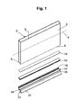
- Fig. 1 shows the particular designed as a glass plate separating element 2, wherein indicated by dashed line 4, that in the vertical direction, the height in a known manner is greater than the width of the separating element.
- the separating element 2 has a thickness 5 and contains beveled bevels 6 at its edges, wherein the base or carrier profile 10 and the sealing profile 12 of the sealing element are arranged and fixed on the lower edge 8.
- the carrier profile 10 is provided as an adhesive 14, in particular an adhesive tape 14, but in the context of the invention, alternatively, the carrier profile by means of another adhesive, such as liquid adhesive in particular, factory-connected to the lower edge of the separating element 2.
- the releasably connected with the carrier profile 10 when necessary and thus replaceable sealing profile 12 has two vertically upwardly directed legs 16, 18 which abut in the region of the lower edge 8, in particular on the existing there chamfers 6 directly and without gaps.
- the legs 16, 18 enclose both the carrier profile and the connecting means 14, which are thus hidden from the sealing profile 12 arranged within the same invisible.
- the sealing profile 12 further includes a pointing into a shower interior baffle 20 and at least one preferably substantially vertically downwardly facing sealing body 22, expediently also a further sealing body 24, wherein the one or more sealing bodies 22, 24 are preferably formed as sealing lips.
- the upper end of the leg 16 which as well as the deflection body 20 faces the shower interior, is formed substantially corresponding and / or konkruent to the associated phase 6 at the lower edge 8 of the separating element 2.
- the upper end of the leg 16 has substantially the same inclination or bevel as the aforementioned phase 6 at the lower edge 8, whereby a secure and gap-free contact and / or sealing at the lower edge 8 is achieved directly with the sealing profile 12.
- Said surface of the leg 16, expediently also of the other leg 18, are arranged and / or aligned concisely to the respective chamfers 6 on the underside of the separating element 2, in particular to the respective surface of the separating element 2 at a predetermined angle, in particular of at least approximately 45 ° inclined arranged.
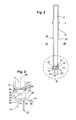
- FIGS. 2 and 3 show as a side view of the separating element 2 with the at its lower edge in particular by means of the adhesive tape 14 fixedly connected carrier profile 10 and releasably connected with this sealing profile 12.
- the carrier profile 10 has a thickness 33 which is smaller by a predetermined amount than the thickness 5 of the separating element. 2
- the thickness 33 of the carrier profile 10 is preferably predetermined such that, together with the thicknesses the two legs 16 and 18, the total width in the region of the carrier profile 10 is approximately the same size as the thickness 5 of the separating element 2, but suitably not greater than said thickness 5 of the separating element 2.
- the separating element 2 has an inner surface 26, which the above Shower interior 28 faces or is assigned, and an outer surface 30, which faces an outer space 32 and assigned.
- the shower interior 28 is shut off from the exterior 32 by means of the separating element 2.
- the surface 34 of the leg 16 is located substantially in the same plane as the upwardly adjoining inner surface 26 of the separating element 2.
- the surface 18 of the leg 18 facing the outer space 32 is substantially in the same plane as the one after
- the transition of said surface 34, 35 to the associated and / or subsequent surfaces of the separating element 2 is continuous and / or gap-free and / or direct such that lime, dirt or the like is not can fix.
- the single transition region in particular from the inner surface 26 to the leg 16 or its surface 34, there is no gap or gap.
- This is expediently analogous to the outer surface 30 and the leg 18.
- between the inner surface 26 and the leg 16 and / or the sealing profile 12 only a single transition region is present, which is preferably continuous.
- the sealing profile 12 includes the first, vertically upwardly directed leg 16, the first surface 34 is arranged flush with the inner surface 26 of the partition member 6.
- the first leg 16 is located directly on the lower edge of the separating element 2, and preferably at the bevel 6 provided there. It is thus only a single transition region between the inner surface 26 and the said surface 34 of the sealing profile or its legs 16 present, with no projections, paragraphs or columns are present, in which lime residues, dirt, deposits or the like could set. Furthermore, a simple cleaning is possible.
- the surface 38 of the deflecting body 20 adjoins the first surface 34 via a rounding 36, whereby water draining away from the inner surface 26 can flow unhindered in this region and limescale deposits, deposits or the like can be avoided and a simple cleaning is made possible.
- the inside 40 of the first leg 16 is at least partially on the support section 10, wherein by means of interlocking locking elements 42, 43, a releasable connection is achieved.
- the locking elements 42,43 are in particular designed as corresponding interlocking cams and grooves.
- the sealing profile 12 further includes a base body 44, which is located below the carrier profile 10.
- the sealing body 22 which is designed in particular as a sealing lip, is furthermore provided, which in an advantageous manner extends substantially vertically downwards.
- the sealing body 22 is advantageously arranged in the connecting region of the first leg 16 and / or the deflecting body 20 with the base body 44.
- the sealing profile 12 preferably has the second leg 18, which is likewise aligned vertically upwards.
- the second leg 18 is similar to the first leg 16 close to the lower edge of the plate-shaped partition member 2, and preferably at least partially on the chamfer existing there 6.
- the outer space 32 facing surface 46 of the second leg 18 is flush with the outer surface 30th of the separating element 2, so that there are no heels, gaps, projections or the like there.
- the sealing profile 12 encloses completely with the two substantially mutually parallel vertically upwardly directed legs 16 and 18 and with the base body 44, the base profile 10.
- the sealing profile 12 is formed substantially U-shaped.
- the second leg 18 is releasably connected by means of locking elements 42, 43 with the base profile 10.
- sealing lip sealing body 24 extends downward, substantially parallel to the first sealing body 22, and preferably has a considerably shorter length than the first sealing body 22.
- Both sealing bodies 22, 24 contain a constriction 48 and / or a reduced cross section, advantageous essentially to the body 44 thereafter, whereby the elasticity is improved.
- the base profile 10 contains a cavity 50 in the interior, whereby a considerable saving of material is achieved and / or a sufficient elasticity is predetermined in order to produce the connection with the sealing profile 12 in a simple manner or to release it as required.
- the carrier profile 10 is formed symmetrically, based on a running through the partition member 2 center plane 52, so that when assembling the factory-side connection of the carrier profile 10 at the lower edge of the separating element 2 no assembly errors can occur, since the two legs 16, 18 of the sealing profile including said locking elements are also formed symmetrically, and thus without difficulty, if necessary, on-site, an alignment of the sealing profile 12 can be made so that the baffle 20 is aligned with the shower interior 28.
Landscapes
- Health & Medical Sciences (AREA)
- Public Health (AREA)
- Epidemiology (AREA)
- General Health & Medical Sciences (AREA)
- Bathtubs, Showers, And Their Attachments (AREA)
- Specific Sealing Or Ventilating Devices For Doors And Windows (AREA)
Abstract
Description
- Die Erfindung bezieht sich auf eine Duschabtrennung mit wenigstens einem schwenkbar angeordneten Trennelement gemäß den im Oberbegriff des Patentanspruchs 1 angegebenen Merkmalen.
- Aus der
EP 2 241 234 A2 ist eine derartige Duschabtrennung mit einem Dichtelement bekannt, welches ein an der Unterkante des Trennelements befestigtes Basisprofil sowie ein mit diesem lösbar und bei Bedarf auswechselbar gekoppeltes Dichtprofil aufweist. Das Trennelement ist im Wesentlichen vertikal angeordnet, und das Basisprofil enthält eine im Wesentlichen horizontal verlaufende Nut, in welche ein Verbindungskörper des Dichtprofils eingreift, wobei mittels Rastelementen eine Fixierung erfolgt. Zwischen der Unterkante des Trennelements und dem genannten Verbindungskörper befindet sich ein ebenfalls im Wesentlichen horizontal verlaufender Teil des Basisprofils. Das Dichtprofil weist einen in einen Duschinnenraum gerichteten Ablenkkörper auf, mittels welchem von der Innenfläche des Trennelements beim Duschen ablaufendes Wasser in den Duschinnenraum abgelenkt wird. Es sind hierbei zwei Übergangsbereiche vorhanden, und zwar zwischen der Innenfläche des Trennelements und dem genannten Teil des Basisprofils und dem nach unten hin anschließenden Ablenkkörper des Dichtprofils. Das derart ausgebildete und angeordnete Dichtelement bedingt aufgrund der genannten horizontalen Nut des Basisprofils und des Verbindungskörpers eine nicht unerhebliche Bauhöhe, zumal das Basisprofil recht steif ausgebildet sein muss, damit der Verbindungskörper und insgesamt das Dichtprofil funktionssicher und dauerhaft fixiert ist. Ferner besteht die Gefahr, dass vor allem durch im Wesentlichen horizontal einwirkende Kräfte aus das Dichtprofil das Dichtprofil unerwünscht aus dem Basisprofil gelöst und von diesem getrennt wird. - Weiterhin ist aus der
DE 202 00 035 U1 eine Vorrichtung zum Abdichten der Schließfuge der Scheibe einer Glastür oder dergleichen bekannt, wobei an einer Kante der Scheibe ein elastisches Dichtungsprofil angeordnet ist. Die genannte Kante weist ein stumpfwinkliges Kantenprofil auf, mit welchem das Dichtungsprofil entweder direkt verklebt oder mit einem Fuß in einer Nut einer zusätzlichen Profilschiene festgelegt ist, wobei die Profilschiene mit dem Kantenprofil der Scheibe verklebt ist. Das Dichtungsprofil und die ggf. vorhandene Profilschiene ragen über die Ebenen der Oberflächen der Scheiben nicht hinaus. Sofern gemäß der erstgenannten Ausführungsform das Dichtungsprofil direkt mit dem Kantenprofil der Scheibe verklebt ist, ist ein Auswechseln des Dichtungsprofils nicht ohne Weiteres möglich. Sofern gemäß der anderen Ausführungsform die Profilschiene vorhanden ist, sind im Bereich der Ebenen der beiden genannten Oberflächen der Scheibe jeweils zwei Übergangsbereiche vorhanden, in welchen sich Kalk, Schmutz oder dergleichen ansammeln können. Ferner ist diese Vorrichtung zum Abdichten der im Wesentlichen vertikal verlaufenden Schließfuge bzw. Kante der Scheibe vorgesehen. - Hiervon ausgehend liegt der Erfindung die Aufgabe zugrunde, die Duschabtrennung der genannten Art mit geringem konstruktivem Aufwand dahingehend weiter zu bilden, dass die aufgezeigten Nachteile vermieden werden und / oder dass eine gleichwohl funktionssichere sowie dauerhafte Festlegung des Dichtprofils erreicht wird. Ferner soll das Dichtelement eine geringe Bauhöhe aufweisen und / oder die Ansammlung von Kalk, Schmutz oder dergleichen reduziert werden. Weiterhin soll eine einfache Reinigung des Trennelements, und zwar insbesondere im Bereich dessen Unterkante, ermöglicht werden.
- Die Lösung dieser Aufgabe erfolgt gemäß den im Patentanspruch 1 angegebenen Merkmalen.
- Die erfindungsgemäß ausgebildete Duschabtrennung und / oder deren Trennelemente zeichnen sich durch eine einfache und funktionsgerechte Konstruktion aus, wobei an der Unterkante des Trennelements nur ein einziger Übergangsbereich zwischen der Innenfläche des Trennelements und dem Dichtelement, nämlich dem Dichtprofil und der Innenfläche, vorhanden ist, und die Außenfläche des Dichtprofilschenkels bündig mit der Innenfläche des Trennelements angeordnet ist. Das Basisprofil, welches auch als Trägerprofil bezeichnet wird, weist eine um einen vorgegebenen Betrag kleinere Breite auf als das Trennelement auf, wobei der genannte nach oben ausgerichtete Schenkel des Dichtprofils an seiner Innenfläche ein Rastelement aufweist, welchem ein korrespondierendes Rastelement des Basisprofils zugeordnet ist. Bevorzugt enthält das Dichtprofil auch im Bereich der Außenfläche des Trennelements einen weiteren, gleichfalls nach oben gerichteten Schenkel, dessen Oberfläche ebenfalls flächenbündig mit der Außenfläche des Trennelements angeordnet ist. Auch dieser weitere Schenkel enthält an seiner Innenseite ein Rastelement korrespondierend zu einem Rastelement des Basisprofils. Das Basisprofil oder Trägerprofil enthält ferner einen Grundkörper, von welchem der erste der Innenfläche zugeordnete Schenkel, zweckmäßig auch der weitere Schenkel nach oben absteht, wobei in bevorzugter Weise im Bereich des Grundkörpers der Ablenkkörper angeordnet und / oder mit dem Dichtprofil verbunden ist. In vorteilhafter Weise schließt an die Oberfläche des ersten Schenkels über eine Abrundung der nach unten in einem vorgegebenen Winkel weisende Ablenkkörper an, so dass über diese Abrundung von der Innenfläche ablaufendes Wasser beim Duschen in den Innenraum abfließen kann, ohne dass in diesem Bereich Kalk, Schmutz oder dergleichen sich ansammeln können. Es sei an dieser Stelle festgehalten, dass die Duschabtrennung als Faltwand mit wenigstens zwei aneinander gelenkten Trennelementen ausgebildet sein kann oder wenigstens ein als Schwenkflügel ausgebildetes Trennelement enthält, welches in einem Rahmen oder an einer feststehenden Wand, insbesondere Raumwand, mittels Scharnieren oder Lagern um eine im Wesentlichen vertikale Achse schwenkbar ist.
- Weiterbildungen und besondere Ausgestaltungen der Erfindung sind in den Unteransprüchen sowie der nachfolgenden Beschreibung eines besonderen Ausführungsbeispiels angegeben und ferner in der Zeichnung dargestellt.
- Die Erfindung wird nachfolgend anhand der in der Zeichnung dargestellten besonderen Ausführungsform näher erläutert, ohne dass insoweit eine Beschränkung erfolgt. Es zeigen in schematischen Darstellungen:
- Fig. 1
- Perspektivisch eine explosionsartige Darstellung des Trennelements und des Dichtelements,
- Fig. 2
- eine Seitenansicht,
- Fig. 3
- vergrößert das Detail A gemäß
Fig. 2 . -
Fig. 1 zeigt das insbesondere als Glasplatte ausgebildete Trennelement 2, wobei mit gestrichelter Linie 4 angedeutet ist, dass in vertikaler Richtung die Höhe in bekannter Weise größer ist als die Breite des Trennelements. Das Trennelement 2 weist eine Dicke 5 auf und enthält an seinen Kanten abgeschrägte Fasen 6, wobei an der Unterkante 8 das Basis- oder Trägerprofil 10 und das Dichtprofil 12 des Dichtelements angeordnet und befestigt sind. Zur Befestigung und/oder Verbindung des Trägerprofils 10 ist als Klebemittel 14, insbesondere ein Klebeband 14 vorgesehen, doch kann im Rahmen der Erfindung alternativ das Trägerprofil mittels eines anderen Klebemittels, wie insbesondere Flüssigklebstoff, werkseitig mit der Unterkante des Trennelements 2 fest verbunden sein. Das bei Bedarf lösbar mit dem Trägerprofil 10 verbundene und somit auswechselbare Dichtprofil 12 weist zwei vertikal nach oben gerichtete Schenkel 16, 18 auf, welche im Bereich der Unterkante 8, insbesondere an den dort vorhandenen Fasen 6 unmittelbar und spaltfrei anliegen. Die Schenkel 16, 18 umschließen sowohl das Trägerprofil als auch das Verbindungsmittel 14, welche somit unsichtbar vom Dichtprofil 12 verdeckt innerhalb desselben angeordnet sind. - Das Dichtprofil 12 enthält ferner einen in einen Duschinnenraum weisenden Ablenkkörper 20 sowie wenigstens einen bevorzugt im Wesentlichen vertikal nach unten weisenden Dichtkörper 22, zweckmäßig auch einen weiteren Dichtkörper 24, wobei der oder die Dichtkörper 22, 24 bevorzugt als Dichtlippen ausgebildet sind. Es ist von besonderer Bedeutung, dass das obere Ende des Schenkels 16, welcher ebenso wie der Ablenkkörper 20 dem Duschinnenraum zugewandt ist, im Wesentlichen korrespondierend und/oder konkruent zur zugeordneten Phase 6 an der Unterkante 8 des Trennelements 2 ausgebildet ist. Insbesondere weist das obere Ende des Schenkels 16 im Wesentlichen die gleiche Neigung oder Abschrägung auf wie die vorgenannte Phase 6 an der Unterkante 8, wodurch eine sichere und spaltfreie Anlage und/oder Abdichtung an der Unterkante 8 unmittelbar mit dem Dichtprofil 12 erreicht ist. Die genannte Oberfläche des Schenkels 16, zweckmäßig auch des anderen Schenkels 18, sind konkruent zu den jeweiligen Fasen 6 an der Unterseite des Trennelements 2 angeordnet und/oder ausgerichtet, insbesondere zur jeweiligen Oberfläche des Trennelements 2 in einem vorgegebenen Winkel, insbesondere von zumindest näherungsweise 45° geneigt angeordnet.
-
Fig. 2 und 3 zeigen als Seitenansicht das Trennelement 2 mit dem an dessen Unterkante insbesondere mittels des Klebebands 14 fest verbundenen Trägerprofils 10 und mit diesem lösbar verbundenen Dichtprofil 12. Das Trägerprofil 10 besitzt eine Dicke 33, welche um einen vorgegebenen Betrag kleiner ist als die Dicke 5 des Trennelements 2. Bevorzugt ist im Rahmen der Erfindung die Dicke 33 des Trägerprofils 10 derart vorgegeben, dass zusammen mit den Dicken der beiden Schenkel 16 und 18 die Gesamtbreite im Bereich des Trägerprofils 10 näherungsweise gleich groß ist wie die Dicke 5 des Trennelements 2, zweckmäßig aber nicht größer ist als die genannte Dicke 5 des Trennelements 2. Das Trennelement 2 besitzt eine Innenfläche 26, welche dem vorgenannten Duschinnenraum 28 zugewandt bzw. zugeordnet ist, und eine Außenfläche 30, welche einem Außenraum 32 zugewandt bzw. zugeordnet ist. Im geschlossenen Zustand der Duschabtrennung wird mittels des Trennelements 2 der Duschinnenraum 28 vom Außenraum 32 abgesperrt. Erfindungsgemäß befindet sich die Oberfläche 34 des Schenkels 16 im Wesentlichen in der gleichen Ebene wie die nach oben anschließende Innenfläche 26 des Trennelements 2. Zusätzlich oder alternativ befindet sich die Oberfläche 18 des dem Außenraum 32 zugewandten Schenkels 18 im Wesentlichen in der gleichen Ebene wie die nach oben anschließende Außenfläche 30 des Trennelements 2. In bevorzugter Weise erfolgt der Übergang der genannten Oberfläche 34, 35 zu den zugeordneten und/oder anschließenden Flächen des Trennelements 2 kontinuierlich und/oder spaltfrei und/oder direkt derart, dass Kalk, Schmutz oder dergleichen sich nicht festsetzen können. Im einzigen Übergangsbereich insbesondere von der Innenfläche 26 zum Schenkel 16 bzw. dessen Oberfläche 34 ist keine Fuge oder kein Spalt vorhanden. Dies gilt zweckmäßig auch bei der Außenfläche 30 und dem Schenkel 18 analog. Insbesondere ist zwischen der Innenfläche 26 und dem Schenkel 16 und/oder dem Dichtprofil 12 nur ein einziger Übergangsbereich vorhanden, welcher bevorzugt kontinuierlich ist. - Das Dichtprofil 12 enthält den ersten, vertikal nach oben gerichteten Schenkel 16, dessen erste Oberfläche 34 flächenbündig zur Innenfläche 26 des Trennelements 6 angeordnet ist. Der erste Schenkel 16 liegt unmittelbar an der Unterkante des Trennelements 2, und zwar bevorzugt an der dort vorgesehenen Fase 6 an. Es ist somit nur ein einziger Übergangsbereich zwischen der Innenfläche 26 und der genannten Oberfläche 34 des Dichtprofils bzw. dessen Schenkel 16 vorhanden, wobei keine Überstande, Absätze oder Spalten vorhanden sind, in welchen sich Kalkrückstände, Schmutz, Ablagerungen oder dergleichen festsetzen könnten. Des Weiteren ist eine einfache Reinigung ermöglicht. In vorteilhafter Weise schließt an die erste Oberfläche 34 über eine Abrundung 36 die Oberfläche 38 des Ablenkkörpers 20 an, wobei auch in diesem Bereich von der Innenfläche 26 ablaufendes Wasser ungehindert abfließen kann und Kalkrückstände, Ablagerungen oder dergleichen vermieden werden sowie eine einfache Reinigung ermöglicht wird. Die Innenseite 40 des ersten Schenkels 16 liegt zumindest teilweise am Trägerprofil 10 an, wobei mittels ineinander greifenden Rastelementen 42, 43 eine lösbare Verbindung erreicht ist. Die Rastelemente 42,43 sind insbesondere als korrespondierende ineinander greifende Nocken und Nuten ausgebildet.
- Das Dichtprofil 12 enthält ferner einen Grundkörper 44, welcher sich unterhalb des Trägerprofils 10 befindet. Am Dichtprofil 12, insbesondere an dessen Grundkörper 44, ist ferner der insbesondere als Dichtlippe ausgebildeter Dichtkörper 22 vorgesehen, welcher sich in vorteilhafter Weise im Wesentlichen vertikal nach unten erstreckt. Der Dichtkörper 22 ist vorteilhaft im Verbindungsbereich des ersten Schenkels 16 und / oder der Ablenkkörpers 20 mit dem Grundkörper 44 angeordnet.
- Des Weiteren weist das Dichtprofil 12 bevorzugt den zweiten Schenkel 18 auf, welcher ebenfalls in vertikaler Richtung nach oben ausgerichtet ist. Der zweite Schenkel 18 liegt analog wie der erste Schenkel 16 dicht an der Unterkante des plattenförmigen Trennelements 2 an, und zwar bevorzugt zumindest teilweise an der dort vorhandenen Fase 6. Die dem Außenraum 32 zugewandte Oberfläche 46 des zweiten Schenkels 18 ist flächenbündig mit der Außenfläche 30 des Trennelements 2, so dass auch dort keine Absätze, Spalte, Überstände oder dergleichen vorhanden sind. In vorteilhafter Weise umschließt das Dichtprofil 12 mit den beiden im Wesentlichen parallel zueinander vertikal nach oben gerichteten Schenkeln 16 und 18 sowie mit dem Grundkörper 44 vollständig das Basisprofil 10. Insoweit ist das Dichtprofil 12 im Wesentlichen U-förmig ausgebildet. Auch der zweite Schenkel 18 ist mittels Rastelementen 42, 43 mit dem Basisprofil 10 lösbar verbunden. Der weitere als Dichtlippe ausgebildete Dichtkörper 24 verläuft nach unten, im Wesentlichen parallel zum ersten Dichtkörper 22, und weist bevorzugt eine erheblich kürzere Länge auf als der erste Dichtkörper 22. Beide Dichtkörper 22, 24 enthalten eine Einschnürung 48 und / oder einen reduzierten Querschnitt, vorteilhaft im Wesentlichen an den Grundkörper 44 anschließend, wodurch die Elastizität verbessert wird.
- In vorteilhafter Weise enthält das Basisprofil 10 im Inneren einen Hohlraum 50, wodurch eine nicht unerhebliche Materialersparnis erzielt wird und / oder eine hinreichende Elastizität vorgegeben ist, um in einfacher Weise die Verbindung mit dem Dichtprofil 12 herzustellen oder bedarfsweise zu lösen. In besonders vorteilhafter Weise ist das Trägerprofil 10 symmetrisch ausgebildet, bezogen auf eine durch das Trennelement 2 verlaufende Mittelebene 52, so dass bei Herstellung der werkseitigen Verbindung des Trägerprofils 10 an der Unterkante des Trennelements 2 keine Montagefehler auftreten können, da auch die beiden Schenkel 16, 18 des Dichtprofils einschließlich der genannten Rastelemente ebenfalls symmetrisch ausgebildet sind, und somit ohne Schwierigkeiten, ggf. vor Ort, eine Ausrichtung des Dichtprofils 12 vorgenommen werden kann, damit der Ablenkkörper 20 zum Duschinnenraum 28 ausgerichtet wird.
-
- 2
- Trennelement / Platte
- 4
- gestrichelte Linie
- 5
- Dicke von 2
- 6
- Fase
- 8
- Unterkante von 2
- 10
- Trägerprofil / Basisprofil
- 12
- Dichtprofil
- 14
- Verbindungsmittel / Klebeband
- 16, 18
- Schenkel von 12
- 20
- Ablenkkörper
- 22
- Dichtkörper / Dichtlippe
- 24
- weiterer Dichtkörper / Dichtlippe
- 26
- Innenfläche von 2
- 28
- Duschinnenraum
- 30
- Außenfläche von 2
- 32
- Außenraum
- 33
- Dicke von 10
- 34
- erste Oberfläche von 16
- 35
- Oberfläche von 18
- 36
- Abrundung zwischen 26 und 38
- 38
- Oberfläche von 20
- 40
- Innenseite von 16
- 42
- Rastelement
- 43
- Rastelement
- 44
- Grundkörper
- 46
- Oberfläche von 18
- 48
- Einschnürung
- 50
- Hohlraum
- 52
- Mittelebene
Claims (13)
- Duschabtrennung mit wenigstens einem schwenkbar angeordneten Trennelement (2) und einem im Bereich der Unterkante(8) des Trennelements (2) angeordnetes Dichtelement, welches ein an der genannten Unterkante befestigtes Basisprofil (10) sowie ein mit diesem lösbar und bei Bedarf auswechselbar gekoppeltes Dichtprofil (12) mit einem Dichtkörper (22) und bevorzugt einem Ablaufkörper (20) aufweist,
dadurch gekennzeichnet, dass das Dichtprofil (12) einen nach oben gerichteten Schenkel (16) aufweist, welcher an der Unterkante (8) des Trennelements (2) anliegt, und dass die Oberfläche (34) des Schenkels (16) bündig mit einer Innenfläche (26) des Trennelements (2) angeordnet ist. - Duschabtrennung nach Anspruch 1, dadurch gekennzeichnet, dass der Schenkel (16) an einer Fase (6) der Unterkante des Trennelements (2) anliegt.
- Duschabtrennung nach Anspruch 1 oder 2, dadurch gekennzeichnet, dass der Schenkel (16) an seiner am Basisprofil (10) bevorzugt anliegenden Innenseite ein Rastelement (42) aufweist und das Basisprofil (10) ein korrespondierend zu jenem ausgebildetes weiteres Rastelement (43) aufweist, wobei die genannten Rastelemente (42, 43) ineinander greifen.
- Duschabtrennung nach einem der Ansprüche 1 bis 3, dadurch gekennzeichnet, dass der Schenkel (16) das Basisprofil (10) sowie ein Klebe- und/oder Verbindungsmittel (14), mit welchem das Basisprofil (10) mit der Unterkante des Trennelements (2) verbunden ist, übergreift.
- Duschabtrennung nach einem der Ansprüche 1 bis 4, dadurch gekennzeichnet, dass das Dichtprofil (12) anschließend an die Oberfläche (34) des Schenkels (16) eine Abrundung (36) aufweist, an welcher die Oberfläche (38) des Ablenkkörpers (20) anschließt.
- Duschabtrennung nach einem der Ansprüche 1 bis 5, dadurch gekennzeichnet, dass das Dichtprofil (12) einen Grundkörper (44) unterhalb des Basisprofils (10) aufweist und dass mit dem Grundkörper (4) der genannte Schenkel (16) verbunden ist, wobei im Verbindungsbereich bevorzugt ferner der Ablenkkörper (20) angeordnet ist.
- Duschabtrennung nach einem der Ansprüche 1 bis 6, dadurch gekennzeichnet, dass der Dichtkörper (22), welcher bevorzugt als Dichtlippe ausgebildet ist, im Verbindungsbereich des Grundkörpers mit dem Schenkel (16) und / oder dem Ablenkkörper (20) angeordnet ist.
- Duschabtrennung nach einem der Ansprüche 1 bis 7, dadurch gekennzeichnet, dass das Dichtprofil (12) gegenüberliegend zum ersten Schenkel (16) einen weiteren Schenkel (18) aufweist, dessen Oberfläche im Wesentlichen bündig mit der Außenfläche (30) des Trennelements (2) angeordnet ist, wobei der Schenkel (18) analog zum ersten Schenkel (16) ein Rastelement aufweist, welches korrespondierend mit einem zugeordneten Rastelement des Basisprofils (10) ausgebildet ist und in Verbindung steht.
- Duschabtrennung nach Anspruch 8, dadurch gekennzeichnet, dass die beiden im Wesentlichen parallel zueinander und beabstandet angeordneten Schenkel (16, 18) zusammen mit dem Grundkörper (44) das Basisprofil (10) umschließen, bevorzugt ferner auch das Klebe- oder Verbindungsmittel (14).
- Duschabtrennung nach einem der Ansprüche 1 bis 9, dadurch gekennzeichnet, dass das Basisprofil (10) symmetrisch, bezogen auf eine durch das Trennelement (2) verlaufende Mittelebene (52), ausgebildet ist.
- Duschabtrennung nach einem derAnsprüche 6 bis 10, dadurch gekennzeichnet, dass am Grundkörper (44) die nach unten gerichtete Dichtlippe (22) und bevorzugt eine weitere Dichtlippe (24) angeordnet sind und / oder dass wenigstens eine der Dichtlippen (22, 24) eine Einschnürung (48) aufweist, welche bevorzugt nahe und / oder im Anschluss an den Grundkörper (44) angeordnet ist.
- Duschabtrennung nach einem der Ansprüche 1 bis 11, dadurch gekennzeichnet, dass das Basisprofil (10) im Inneren einen insbesondere geschlossenen Hohlraum (50) aufweist.
- Duschabtrennung nach einem der Ansprüche 1 bis 12, dadurch gekennzeichnet, dass das Basisprofil (10) eine Dicke aufweist, welche um einen vorgegebenen Betrag kleiner ist als der Abstand zwischen der Innenfläche (26) und der Außenfläche (30) des Trennelements (2).
Applications Claiming Priority (1)
| Application Number | Priority Date | Filing Date | Title |
|---|---|---|---|
| DE202011103977U DE202011103977U1 (de) | 2011-08-03 | 2011-08-03 | Duschabtrennung |
Publications (3)
| Publication Number | Publication Date |
|---|---|
| EP2554082A2 true EP2554082A2 (de) | 2013-02-06 |
| EP2554082A3 EP2554082A3 (de) | 2014-04-02 |
| EP2554082B1 EP2554082B1 (de) | 2016-08-24 |
Family
ID=46679048
Family Applications (1)
| Application Number | Title | Priority Date | Filing Date |
|---|---|---|---|
| EP12005083.6A Not-in-force EP2554082B1 (de) | 2011-08-03 | 2012-07-10 | Duschabtrennung |
Country Status (3)
| Country | Link |
|---|---|
| EP (1) | EP2554082B1 (de) |
| DE (1) | DE202011103977U1 (de) |
| ES (1) | ES2604696T3 (de) |
Families Citing this family (1)
| Publication number | Priority date | Publication date | Assignee | Title |
|---|---|---|---|---|
| DE202015004556U1 (de) | 2015-06-05 | 2016-09-06 | Schulte Duschkabinenbau Gmbh & Co. Kg | Dichtprofil und Duschabtrennung |
Citations (2)
| Publication number | Priority date | Publication date | Assignee | Title |
|---|---|---|---|---|
| DE20200035U1 (de) | 2002-01-02 | 2002-05-08 | Hommel, Günter, 71229 Leonberg | Vorrichtung zum Abdichten der Schließfuge der Scheibe einer Glastür o.dgl. |
| EP2241234A2 (de) | 2009-03-06 | 2010-10-20 | Altura Leiden Holding B.V. | Duschabtrennung |
Family Cites Families (5)
| Publication number | Priority date | Publication date | Assignee | Title |
|---|---|---|---|---|
| US1944440A (en) * | 1929-12-14 | 1934-01-23 | Louis H Lehman | Shower bath stall door, shower bath shield, and the like |
| DE10052507A1 (de) * | 2000-10-23 | 2002-04-25 | Queen Sanitaer Produkte Gmbh | Randprofil für eine Duschentrennwand |
| DE10103791A1 (de) * | 2001-01-28 | 2002-08-01 | Bernd Falke | Schwallschutz-Schiene für Duschen und Türen |
| DE10222469A1 (de) * | 2002-04-15 | 2003-10-23 | Werner Scholpp | Mehrteilige Dichtung für Duschabtrennungen |
| DE102008017851A1 (de) * | 2008-04-09 | 2009-10-15 | Rehau Ag + Co. | Verfahren zur Herstellung eines Dekorprofils an dem wenigstens ein Funktionselement angebracht ist |
-
2011
- 2011-08-03 DE DE202011103977U patent/DE202011103977U1/de not_active Expired - Lifetime
-
2012
- 2012-07-10 EP EP12005083.6A patent/EP2554082B1/de not_active Not-in-force
- 2012-07-10 ES ES12005083.6T patent/ES2604696T3/es active Active
Patent Citations (2)
| Publication number | Priority date | Publication date | Assignee | Title |
|---|---|---|---|---|
| DE20200035U1 (de) | 2002-01-02 | 2002-05-08 | Hommel, Günter, 71229 Leonberg | Vorrichtung zum Abdichten der Schließfuge der Scheibe einer Glastür o.dgl. |
| EP2241234A2 (de) | 2009-03-06 | 2010-10-20 | Altura Leiden Holding B.V. | Duschabtrennung |
Also Published As
| Publication number | Publication date |
|---|---|
| DE202011103977U1 (de) | 2012-11-23 |
| EP2554082A3 (de) | 2014-04-02 |
| EP2554082B1 (de) | 2016-08-24 |
| ES2604696T3 (es) | 2017-03-08 |
Similar Documents
| Publication | Publication Date | Title |
|---|---|---|
| EP3259428B1 (de) | Dichtungsvorrichtung für fenster- und türelemente | |
| EP0118883B1 (de) | Duschabtrennung in Form einer Klapptür | |
| EP2618706B1 (de) | Duschwand mit einer schiebetür | |
| EP2554082B1 (de) | Duschabtrennung | |
| DE2911728A1 (de) | Faltwand fuer bade- oder duschwannen | |
| DE102014111014A1 (de) | WC-Sitz und Verwendung von Dichtmitteln zur Nachrüstung eines WC-Sitzes | |
| CH714559A2 (de) | Bauelement zum Verschliessen einer Öffnung in einem Bauwerk, insbesondere Fensterelement. | |
| DE4124809C1 (en) | Seal for shower cubicle with hinged leaf - has two magnet parts, one under leaf, swivelling about horizontal axis, and one leaf lower edge | |
| EP3064113B1 (de) | Duschabtrennung | |
| DE29900425U1 (de) | Bandanordnung für Türen, Fenster u.dgl. | |
| AT17077U1 (de) | System zur Montage einer Fensterbank an einer Außenfassade | |
| DE102018112430A1 (de) | Fenster | |
| EP3680438B1 (de) | Anordnung aus einem rahmenprofil und einem dichtprofil für einen fenster- oder türrahmen | |
| DE202007009636U1 (de) | Flügelanordnung | |
| DE19703790C2 (de) | Duschkabine | |
| DE102016125334A1 (de) | Fenster oder Tür mit einer Dichtungsanordnung und Falzdichtung | |
| WO2006010477A1 (de) | An einem vertikalen rahmenprofil eines türflügels angeordnete dichtung | |
| EP3420149B1 (de) | Anschlusseinrichtung zwischen rinne und sinkkasten | |
| DE19847657C1 (de) | Profildichtung sowie zugehörige Schiebetür mit entsprechender Profildichtung | |
| DE4008160A1 (de) | Trennwand fuer wannen | |
| DE20211901U1 (de) | Trennwand | |
| EP4534793A1 (de) | Tür- oder fensteranordnung | |
| DE1878571U (de) | Schiebefluegelrahmen. | |
| EP0958774A2 (de) | Duschabtrennung | |
| EP3075941B1 (de) | Gebäudeverschlusselement |
Legal Events
| Date | Code | Title | Description |
|---|---|---|---|
| PUAI | Public reference made under article 153(3) epc to a published international application that has entered the european phase |
Free format text: ORIGINAL CODE: 0009012 |
|
| 17P | Request for examination filed |
Effective date: 20120710 |
|
| AK | Designated contracting states |
Kind code of ref document: A2 Designated state(s): AL AT BE BG CH CY CZ DE DK EE ES FI FR GB GR HR HU IE IS IT LI LT LU LV MC MK MT NL NO PL PT RO RS SE SI SK SM TR |
|
| AX | Request for extension of the european patent |
Extension state: BA ME |
|
| PUAL | Search report despatched |
Free format text: ORIGINAL CODE: 0009013 |
|
| AK | Designated contracting states |
Kind code of ref document: A3 Designated state(s): AL AT BE BG CH CY CZ DE DK EE ES FI FR GB GR HR HU IE IS IT LI LT LU LV MC MK MT NL NO PL PT RO RS SE SI SK SM TR |
|
| AX | Request for extension of the european patent |
Extension state: BA ME |
|
| RIC1 | Information provided on ipc code assigned before grant |
Ipc: A47K 3/36 20060101AFI20140224BHEP |
|
| 17Q | First examination report despatched |
Effective date: 20140319 |
|
| 17Q | First examination report despatched |
Effective date: 20140916 |
|
| GRAP | Despatch of communication of intention to grant a patent |
Free format text: ORIGINAL CODE: EPIDOSNIGR1 |
|
| INTG | Intention to grant announced |
Effective date: 20160411 |
|
| GRAS | Grant fee paid |
Free format text: ORIGINAL CODE: EPIDOSNIGR3 |
|
| GRAA | (expected) grant |
Free format text: ORIGINAL CODE: 0009210 |
|
| AK | Designated contracting states |
Kind code of ref document: B1 Designated state(s): AL AT BE BG CH CY CZ DE DK EE ES FI FR GB GR HR HU IE IS IT LI LT LU LV MC MK MT NL NO PL PT RO RS SE SI SK SM TR |
|
| REG | Reference to a national code |
Ref country code: GB Ref legal event code: FG4D Free format text: NOT ENGLISH |
|
| REG | Reference to a national code |
Ref country code: CH Ref legal event code: EP |
|
| REG | Reference to a national code |
Ref country code: AT Ref legal event code: REF Ref document number: 822274 Country of ref document: AT Kind code of ref document: T Effective date: 20160915 |
|
| REG | Reference to a national code |
Ref country code: IE Ref legal event code: FG4D Free format text: LANGUAGE OF EP DOCUMENT: GERMAN |
|
| REG | Reference to a national code |
Ref country code: DE Ref legal event code: R096 Ref document number: 502012008017 Country of ref document: DE |
|
| REG | Reference to a national code |
Ref country code: NL Ref legal event code: FP |
|
| REG | Reference to a national code |
Ref country code: LT Ref legal event code: MG4D |
|
| PG25 | Lapsed in a contracting state [announced via postgrant information from national office to epo] |
Ref country code: HR Free format text: LAPSE BECAUSE OF FAILURE TO SUBMIT A TRANSLATION OF THE DESCRIPTION OR TO PAY THE FEE WITHIN THE PRESCRIBED TIME-LIMIT Effective date: 20160824 Ref country code: NO Free format text: LAPSE BECAUSE OF FAILURE TO SUBMIT A TRANSLATION OF THE DESCRIPTION OR TO PAY THE FEE WITHIN THE PRESCRIBED TIME-LIMIT Effective date: 20161124 Ref country code: LT Free format text: LAPSE BECAUSE OF FAILURE TO SUBMIT A TRANSLATION OF THE DESCRIPTION OR TO PAY THE FEE WITHIN THE PRESCRIBED TIME-LIMIT Effective date: 20160824 Ref country code: FI Free format text: LAPSE BECAUSE OF FAILURE TO SUBMIT A TRANSLATION OF THE DESCRIPTION OR TO PAY THE FEE WITHIN THE PRESCRIBED TIME-LIMIT Effective date: 20160824 Ref country code: RS Free format text: LAPSE BECAUSE OF FAILURE TO SUBMIT A TRANSLATION OF THE DESCRIPTION OR TO PAY THE FEE WITHIN THE PRESCRIBED TIME-LIMIT Effective date: 20160824 |
|
| PG25 | Lapsed in a contracting state [announced via postgrant information from national office to epo] |
Ref country code: SE Free format text: LAPSE BECAUSE OF FAILURE TO SUBMIT A TRANSLATION OF THE DESCRIPTION OR TO PAY THE FEE WITHIN THE PRESCRIBED TIME-LIMIT Effective date: 20160824 Ref country code: PT Free format text: LAPSE BECAUSE OF FAILURE TO SUBMIT A TRANSLATION OF THE DESCRIPTION OR TO PAY THE FEE WITHIN THE PRESCRIBED TIME-LIMIT Effective date: 20161226 Ref country code: LV Free format text: LAPSE BECAUSE OF FAILURE TO SUBMIT A TRANSLATION OF THE DESCRIPTION OR TO PAY THE FEE WITHIN THE PRESCRIBED TIME-LIMIT Effective date: 20160824 Ref country code: GR Free format text: LAPSE BECAUSE OF FAILURE TO SUBMIT A TRANSLATION OF THE DESCRIPTION OR TO PAY THE FEE WITHIN THE PRESCRIBED TIME-LIMIT Effective date: 20161125 |
|
| REG | Reference to a national code |
Ref country code: ES Ref legal event code: FG2A Ref document number: 2604696 Country of ref document: ES Kind code of ref document: T3 Effective date: 20170308 |
|
| REG | Reference to a national code |
Ref country code: DE Ref legal event code: R082 Ref document number: 502012008017 Country of ref document: DE Representative=s name: REBLE KLOSE SCHMITT PARTNERSCHAFTSGESELLSCHAFT, DE |
|
| PG25 | Lapsed in a contracting state [announced via postgrant information from national office to epo] |
Ref country code: EE Free format text: LAPSE BECAUSE OF FAILURE TO SUBMIT A TRANSLATION OF THE DESCRIPTION OR TO PAY THE FEE WITHIN THE PRESCRIBED TIME-LIMIT Effective date: 20160824 Ref country code: RO Free format text: LAPSE BECAUSE OF FAILURE TO SUBMIT A TRANSLATION OF THE DESCRIPTION OR TO PAY THE FEE WITHIN THE PRESCRIBED TIME-LIMIT Effective date: 20160824 |
|
| REG | Reference to a national code |
Ref country code: DE Ref legal event code: R097 Ref document number: 502012008017 Country of ref document: DE |
|
| PG25 | Lapsed in a contracting state [announced via postgrant information from national office to epo] |
Ref country code: SK Free format text: LAPSE BECAUSE OF FAILURE TO SUBMIT A TRANSLATION OF THE DESCRIPTION OR TO PAY THE FEE WITHIN THE PRESCRIBED TIME-LIMIT Effective date: 20160824 Ref country code: CZ Free format text: LAPSE BECAUSE OF FAILURE TO SUBMIT A TRANSLATION OF THE DESCRIPTION OR TO PAY THE FEE WITHIN THE PRESCRIBED TIME-LIMIT Effective date: 20160824 Ref country code: SM Free format text: LAPSE BECAUSE OF FAILURE TO SUBMIT A TRANSLATION OF THE DESCRIPTION OR TO PAY THE FEE WITHIN THE PRESCRIBED TIME-LIMIT Effective date: 20160824 Ref country code: BG Free format text: LAPSE BECAUSE OF FAILURE TO SUBMIT A TRANSLATION OF THE DESCRIPTION OR TO PAY THE FEE WITHIN THE PRESCRIBED TIME-LIMIT Effective date: 20161124 Ref country code: DK Free format text: LAPSE BECAUSE OF FAILURE TO SUBMIT A TRANSLATION OF THE DESCRIPTION OR TO PAY THE FEE WITHIN THE PRESCRIBED TIME-LIMIT Effective date: 20160824 Ref country code: PL Free format text: LAPSE BECAUSE OF FAILURE TO SUBMIT A TRANSLATION OF THE DESCRIPTION OR TO PAY THE FEE WITHIN THE PRESCRIBED TIME-LIMIT Effective date: 20160824 |
|
| PLBE | No opposition filed within time limit |
Free format text: ORIGINAL CODE: 0009261 |
|
| STAA | Information on the status of an ep patent application or granted ep patent |
Free format text: STATUS: NO OPPOSITION FILED WITHIN TIME LIMIT |
|
| REG | Reference to a national code |
Ref country code: FR Ref legal event code: PLFP Year of fee payment: 6 |
|
| 26N | No opposition filed |
Effective date: 20170526 |
|
| PG25 | Lapsed in a contracting state [announced via postgrant information from national office to epo] |
Ref country code: SI Free format text: LAPSE BECAUSE OF FAILURE TO SUBMIT A TRANSLATION OF THE DESCRIPTION OR TO PAY THE FEE WITHIN THE PRESCRIBED TIME-LIMIT Effective date: 20160824 |
|
| GBPC | Gb: european patent ceased through non-payment of renewal fee |
Effective date: 20170710 |
|
| REG | Reference to a national code |
Ref country code: IE Ref legal event code: MM4A |
|
| PG25 | Lapsed in a contracting state [announced via postgrant information from national office to epo] |
Ref country code: GB Free format text: LAPSE BECAUSE OF NON-PAYMENT OF DUE FEES Effective date: 20170710 Ref country code: IE Free format text: LAPSE BECAUSE OF NON-PAYMENT OF DUE FEES Effective date: 20170710 |
|
| PG25 | Lapsed in a contracting state [announced via postgrant information from national office to epo] |
Ref country code: LU Free format text: LAPSE BECAUSE OF NON-PAYMENT OF DUE FEES Effective date: 20170710 |
|
| REG | Reference to a national code |
Ref country code: FR Ref legal event code: PLFP Year of fee payment: 7 |
|
| PG25 | Lapsed in a contracting state [announced via postgrant information from national office to epo] |
Ref country code: MT Free format text: LAPSE BECAUSE OF FAILURE TO SUBMIT A TRANSLATION OF THE DESCRIPTION OR TO PAY THE FEE WITHIN THE PRESCRIBED TIME-LIMIT Effective date: 20160824 |
|
| PG25 | Lapsed in a contracting state [announced via postgrant information from national office to epo] |
Ref country code: AL Free format text: LAPSE BECAUSE OF FAILURE TO SUBMIT A TRANSLATION OF THE DESCRIPTION OR TO PAY THE FEE WITHIN THE PRESCRIBED TIME-LIMIT Effective date: 20160824 |
|
| PGFP | Annual fee paid to national office [announced via postgrant information from national office to epo] |
Ref country code: IT Payment date: 20180720 Year of fee payment: 7 Ref country code: FR Payment date: 20180723 Year of fee payment: 7 Ref country code: NL Payment date: 20180723 Year of fee payment: 7 Ref country code: DE Payment date: 20180725 Year of fee payment: 7 Ref country code: ES Payment date: 20180829 Year of fee payment: 7 |
|
| PGFP | Annual fee paid to national office [announced via postgrant information from national office to epo] |
Ref country code: AT Payment date: 20180719 Year of fee payment: 7 Ref country code: CH Payment date: 20180725 Year of fee payment: 7 Ref country code: BE Payment date: 20180723 Year of fee payment: 7 |
|
| PG25 | Lapsed in a contracting state [announced via postgrant information from national office to epo] |
Ref country code: HU Free format text: LAPSE BECAUSE OF FAILURE TO SUBMIT A TRANSLATION OF THE DESCRIPTION OR TO PAY THE FEE WITHIN THE PRESCRIBED TIME-LIMIT; INVALID AB INITIO Effective date: 20120710 Ref country code: MC Free format text: LAPSE BECAUSE OF FAILURE TO SUBMIT A TRANSLATION OF THE DESCRIPTION OR TO PAY THE FEE WITHIN THE PRESCRIBED TIME-LIMIT Effective date: 20160824 |
|
| PG25 | Lapsed in a contracting state [announced via postgrant information from national office to epo] |
Ref country code: CY Free format text: LAPSE BECAUSE OF NON-PAYMENT OF DUE FEES Effective date: 20160824 |
|
| PG25 | Lapsed in a contracting state [announced via postgrant information from national office to epo] |
Ref country code: MK Free format text: LAPSE BECAUSE OF FAILURE TO SUBMIT A TRANSLATION OF THE DESCRIPTION OR TO PAY THE FEE WITHIN THE PRESCRIBED TIME-LIMIT Effective date: 20160824 |
|
| REG | Reference to a national code |
Ref country code: DE Ref legal event code: R119 Ref document number: 502012008017 Country of ref document: DE |
|
| REG | Reference to a national code |
Ref country code: CH Ref legal event code: PL |
|
| REG | Reference to a national code |
Ref country code: AT Ref legal event code: MM01 Ref document number: 822274 Country of ref document: AT Kind code of ref document: T Effective date: 20190710 |
|
| PG25 | Lapsed in a contracting state [announced via postgrant information from national office to epo] |
Ref country code: TR Free format text: LAPSE BECAUSE OF FAILURE TO SUBMIT A TRANSLATION OF THE DESCRIPTION OR TO PAY THE FEE WITHIN THE PRESCRIBED TIME-LIMIT Effective date: 20160824 |
|
| REG | Reference to a national code |
Ref country code: BE Ref legal event code: MM Effective date: 20190731 |
|
| PG25 | Lapsed in a contracting state [announced via postgrant information from national office to epo] |
Ref country code: DE Free format text: LAPSE BECAUSE OF NON-PAYMENT OF DUE FEES Effective date: 20200201 Ref country code: NL Free format text: LAPSE BECAUSE OF NON-PAYMENT OF DUE FEES Effective date: 20190801 Ref country code: AT Free format text: LAPSE BECAUSE OF NON-PAYMENT OF DUE FEES Effective date: 20190710 |
|
| REG | Reference to a national code |
Ref country code: NL Ref legal event code: MM Effective date: 20190801 |
|
| PG25 | Lapsed in a contracting state [announced via postgrant information from national office to epo] |
Ref country code: BE Free format text: LAPSE BECAUSE OF NON-PAYMENT OF DUE FEES Effective date: 20190731 Ref country code: CH Free format text: LAPSE BECAUSE OF NON-PAYMENT OF DUE FEES Effective date: 20190731 Ref country code: LI Free format text: LAPSE BECAUSE OF NON-PAYMENT OF DUE FEES Effective date: 20190731 |
|
| PG25 | Lapsed in a contracting state [announced via postgrant information from national office to epo] |
Ref country code: FR Free format text: LAPSE BECAUSE OF NON-PAYMENT OF DUE FEES Effective date: 20190731 |
|
| PG25 | Lapsed in a contracting state [announced via postgrant information from national office to epo] |
Ref country code: IS Free format text: LAPSE BECAUSE OF FAILURE TO SUBMIT A TRANSLATION OF THE DESCRIPTION OR TO PAY THE FEE WITHIN THE PRESCRIBED TIME-LIMIT Effective date: 20161224 |
|
| PG25 | Lapsed in a contracting state [announced via postgrant information from national office to epo] |
Ref country code: IT Free format text: LAPSE BECAUSE OF NON-PAYMENT OF DUE FEES Effective date: 20190710 |
|
| REG | Reference to a national code |
Ref country code: ES Ref legal event code: FD2A Effective date: 20201126 |
|
| PG25 | Lapsed in a contracting state [announced via postgrant information from national office to epo] |
Ref country code: ES Free format text: LAPSE BECAUSE OF NON-PAYMENT OF DUE FEES Effective date: 20190711 |