EP2554925A2 - Élément d'appui pour un module solaire - Google Patents
Élément d'appui pour un module solaire Download PDFInfo
- Publication number
- EP2554925A2 EP2554925A2 EP12177838A EP12177838A EP2554925A2 EP 2554925 A2 EP2554925 A2 EP 2554925A2 EP 12177838 A EP12177838 A EP 12177838A EP 12177838 A EP12177838 A EP 12177838A EP 2554925 A2 EP2554925 A2 EP 2554925A2
- Authority
- EP
- European Patent Office
- Prior art keywords
- base portion
- support
- fastening
- fastening element
- solar module
- Prior art date
- Legal status (The legal status is an assumption and is not a legal conclusion. Google has not performed a legal analysis and makes no representation as to the accuracy of the status listed.)
- Granted
Links
- 238000003780 insertion Methods 0.000 claims abstract description 5
- 230000037431 insertion Effects 0.000 claims abstract description 5
- 229910052782 aluminium Inorganic materials 0.000 claims description 15
- XAGFODPZIPBFFR-UHFFFAOYSA-N aluminium Chemical compound [Al] XAGFODPZIPBFFR-UHFFFAOYSA-N 0.000 claims description 15
- 229910052751 metal Inorganic materials 0.000 claims description 10
- 239000002184 metal Substances 0.000 claims description 10
- 125000006850 spacer group Chemical group 0.000 claims description 10
- 238000005452 bending Methods 0.000 claims description 9
- 239000004033 plastic Substances 0.000 claims description 9
- 238000005520 cutting process Methods 0.000 claims description 3
- 239000000853 adhesive Substances 0.000 claims description 2
- 230000001070 adhesive effect Effects 0.000 claims description 2
- 239000002991 molded plastic Substances 0.000 claims description 2
- 229910001220 stainless steel Inorganic materials 0.000 claims description 2
- 239000010935 stainless steel Substances 0.000 claims description 2
- 238000004873 anchoring Methods 0.000 claims 1
- 238000000748 compression moulding Methods 0.000 claims 1
- 238000010137 moulding (plastic) Methods 0.000 claims 1
- 230000000630 rising effect Effects 0.000 claims 1
- 238000003860 storage Methods 0.000 description 7
- 238000010276 construction Methods 0.000 description 6
- 239000007788 liquid Substances 0.000 description 5
- 238000004519 manufacturing process Methods 0.000 description 5
- 238000009749 continuous casting Methods 0.000 description 4
- 238000013461 design Methods 0.000 description 4
- 239000000463 material Substances 0.000 description 4
- 239000002131 composite material Substances 0.000 description 3
- 238000005553 drilling Methods 0.000 description 3
- 238000009434 installation Methods 0.000 description 3
- 238000013459 approach Methods 0.000 description 2
- 238000006243 chemical reaction Methods 0.000 description 2
- 238000002360 preparation method Methods 0.000 description 2
- 230000000284 resting effect Effects 0.000 description 2
- XLYOFNOQVPJJNP-UHFFFAOYSA-N water Substances O XLYOFNOQVPJJNP-UHFFFAOYSA-N 0.000 description 2
- 230000001174 ascending effect Effects 0.000 description 1
- 230000009286 beneficial effect Effects 0.000 description 1
- 230000015572 biosynthetic process Effects 0.000 description 1
- 230000001419 dependent effect Effects 0.000 description 1
- 230000000694 effects Effects 0.000 description 1
- 230000005611 electricity Effects 0.000 description 1
- 238000005516 engineering process Methods 0.000 description 1
- 230000002349 favourable effect Effects 0.000 description 1
- 238000010438 heat treatment Methods 0.000 description 1
- 238000001746 injection moulding Methods 0.000 description 1
- 238000003698 laser cutting Methods 0.000 description 1
- 238000000034 method Methods 0.000 description 1
- 238000010079 rubber tapping Methods 0.000 description 1
- 238000000926 separation method Methods 0.000 description 1
- 239000000243 solution Substances 0.000 description 1
- 238000012549 training Methods 0.000 description 1
Images



Classifications
-
- H—ELECTRICITY
- H02—GENERATION; CONVERSION OR DISTRIBUTION OF ELECTRIC POWER
- H02S—GENERATION OF ELECTRIC POWER BY CONVERSION OF INFRARED RADIATION, VISIBLE LIGHT OR ULTRAVIOLET LIGHT, e.g. USING PHOTOVOLTAIC [PV] MODULES
- H02S20/00—Supporting structures for PV modules
- H02S20/20—Supporting structures directly fixed to an immovable object
- H02S20/22—Supporting structures directly fixed to an immovable object specially adapted for buildings
- H02S20/23—Supporting structures directly fixed to an immovable object specially adapted for buildings specially adapted for roof structures
-
- F—MECHANICAL ENGINEERING; LIGHTING; HEATING; WEAPONS; BLASTING
- F24—HEATING; RANGES; VENTILATING
- F24S—SOLAR HEAT COLLECTORS; SOLAR HEAT SYSTEMS
- F24S25/00—Arrangement of stationary mountings or supports for solar heat collector modules
- F24S25/10—Arrangement of stationary mountings or supports for solar heat collector modules extending in directions away from a supporting surface
- F24S25/13—Profile arrangements, e.g. trusses
-
- F—MECHANICAL ENGINEERING; LIGHTING; HEATING; WEAPONS; BLASTING
- F24—HEATING; RANGES; VENTILATING
- F24S—SOLAR HEAT COLLECTORS; SOLAR HEAT SYSTEMS
- F24S25/00—Arrangement of stationary mountings or supports for solar heat collector modules
- F24S25/10—Arrangement of stationary mountings or supports for solar heat collector modules extending in directions away from a supporting surface
- F24S25/15—Arrangement of stationary mountings or supports for solar heat collector modules extending in directions away from a supporting surface using bent plates; using assemblies of plates
-
- F—MECHANICAL ENGINEERING; LIGHTING; HEATING; WEAPONS; BLASTING
- F24—HEATING; RANGES; VENTILATING
- F24S—SOLAR HEAT COLLECTORS; SOLAR HEAT SYSTEMS
- F24S25/00—Arrangement of stationary mountings or supports for solar heat collector modules
- F24S25/10—Arrangement of stationary mountings or supports for solar heat collector modules extending in directions away from a supporting surface
- F24S25/16—Arrangement of interconnected standing structures; Standing structures having separate supporting portions for adjacent modules
-
- F—MECHANICAL ENGINEERING; LIGHTING; HEATING; WEAPONS; BLASTING
- F24—HEATING; RANGES; VENTILATING
- F24S—SOLAR HEAT COLLECTORS; SOLAR HEAT SYSTEMS
- F24S25/00—Arrangement of stationary mountings or supports for solar heat collector modules
- F24S25/30—Arrangement of stationary mountings or supports for solar heat collector modules using elongate rigid mounting elements extending substantially along the supporting surface, e.g. for covering buildings with solar heat collectors
-
- F—MECHANICAL ENGINEERING; LIGHTING; HEATING; WEAPONS; BLASTING
- F24—HEATING; RANGES; VENTILATING
- F24S—SOLAR HEAT COLLECTORS; SOLAR HEAT SYSTEMS
- F24S25/00—Arrangement of stationary mountings or supports for solar heat collector modules
- F24S25/60—Fixation means, e.g. fasteners, specially adapted for supporting solar heat collector modules
- F24S25/63—Fixation means, e.g. fasteners, specially adapted for supporting solar heat collector modules for fixing modules or their peripheral frames to supporting elements
-
- F—MECHANICAL ENGINEERING; LIGHTING; HEATING; WEAPONS; BLASTING
- F24—HEATING; RANGES; VENTILATING
- F24S—SOLAR HEAT COLLECTORS; SOLAR HEAT SYSTEMS
- F24S25/00—Arrangement of stationary mountings or supports for solar heat collector modules
- F24S25/60—Fixation means, e.g. fasteners, specially adapted for supporting solar heat collector modules
- F24S25/63—Fixation means, e.g. fasteners, specially adapted for supporting solar heat collector modules for fixing modules or their peripheral frames to supporting elements
- F24S25/634—Clamps; Clips
-
- F—MECHANICAL ENGINEERING; LIGHTING; HEATING; WEAPONS; BLASTING
- F24—HEATING; RANGES; VENTILATING
- F24S—SOLAR HEAT COLLECTORS; SOLAR HEAT SYSTEMS
- F24S40/00—Safety or protection arrangements of solar heat collectors; Preventing malfunction of solar heat collectors
- F24S40/80—Accommodating differential expansion of solar collector elements
- F24S40/85—Arrangements for protecting solar collectors against adverse weather conditions
-
- F—MECHANICAL ENGINEERING; LIGHTING; HEATING; WEAPONS; BLASTING
- F24—HEATING; RANGES; VENTILATING
- F24S—SOLAR HEAT COLLECTORS; SOLAR HEAT SYSTEMS
- F24S25/00—Arrangement of stationary mountings or supports for solar heat collector modules
- F24S25/60—Fixation means, e.g. fasteners, specially adapted for supporting solar heat collector modules
- F24S2025/6002—Fixation means, e.g. fasteners, specially adapted for supporting solar heat collector modules by using hooks
-
- F—MECHANICAL ENGINEERING; LIGHTING; HEATING; WEAPONS; BLASTING
- F24—HEATING; RANGES; VENTILATING
- F24S—SOLAR HEAT COLLECTORS; SOLAR HEAT SYSTEMS
- F24S25/00—Arrangement of stationary mountings or supports for solar heat collector modules
- F24S2025/80—Special profiles
- F24S2025/801—Special profiles having hollow parts with closed cross-section
-
- Y—GENERAL TAGGING OF NEW TECHNOLOGICAL DEVELOPMENTS; GENERAL TAGGING OF CROSS-SECTIONAL TECHNOLOGIES SPANNING OVER SEVERAL SECTIONS OF THE IPC; TECHNICAL SUBJECTS COVERED BY FORMER USPC CROSS-REFERENCE ART COLLECTIONS [XRACs] AND DIGESTS
- Y02—TECHNOLOGIES OR APPLICATIONS FOR MITIGATION OR ADAPTATION AGAINST CLIMATE CHANGE
- Y02B—CLIMATE CHANGE MITIGATION TECHNOLOGIES RELATED TO BUILDINGS, e.g. HOUSING, HOUSE APPLIANCES OR RELATED END-USER APPLICATIONS
- Y02B10/00—Integration of renewable energy sources in buildings
- Y02B10/10—Photovoltaic [PV]
-
- Y—GENERAL TAGGING OF NEW TECHNOLOGICAL DEVELOPMENTS; GENERAL TAGGING OF CROSS-SECTIONAL TECHNOLOGIES SPANNING OVER SEVERAL SECTIONS OF THE IPC; TECHNICAL SUBJECTS COVERED BY FORMER USPC CROSS-REFERENCE ART COLLECTIONS [XRACs] AND DIGESTS
- Y02—TECHNOLOGIES OR APPLICATIONS FOR MITIGATION OR ADAPTATION AGAINST CLIMATE CHANGE
- Y02E—REDUCTION OF GREENHOUSE GAS [GHG] EMISSIONS, RELATED TO ENERGY GENERATION, TRANSMISSION OR DISTRIBUTION
- Y02E10/00—Energy generation through renewable energy sources
- Y02E10/40—Solar thermal energy, e.g. solar towers
- Y02E10/47—Mountings or tracking
-
- Y—GENERAL TAGGING OF NEW TECHNOLOGICAL DEVELOPMENTS; GENERAL TAGGING OF CROSS-SECTIONAL TECHNOLOGIES SPANNING OVER SEVERAL SECTIONS OF THE IPC; TECHNICAL SUBJECTS COVERED BY FORMER USPC CROSS-REFERENCE ART COLLECTIONS [XRACs] AND DIGESTS
- Y02—TECHNOLOGIES OR APPLICATIONS FOR MITIGATION OR ADAPTATION AGAINST CLIMATE CHANGE
- Y02E—REDUCTION OF GREENHOUSE GAS [GHG] EMISSIONS, RELATED TO ENERGY GENERATION, TRANSMISSION OR DISTRIBUTION
- Y02E10/00—Energy generation through renewable energy sources
- Y02E10/50—Photovoltaic [PV] energy
Definitions
- the invention relates to a support element for mounting a solar module on a substructure.
- the invention refers to "substructure" any type of roofs or shelves, profiled mounting rails that rest on a roof or on a floor or attached to stud structures and have at least one C-profile in the longitudinal direction or a longitudinal screw on which the support element can be fastened by means of a screw.
- the known support elements essentially have a triangular shape, preferably the shape of a right-angled triangle, wherein the hypotenuse is designed as a support surface for a solar module.
- U1 is a substructure for a modular system, in particular a solar module system, known with at least one module having, inter alia, a support rail having a longitudinal groove along the longitudinal axis for receiving an electrical line and at least one transverse groove perpendicular to the longitudinal axis for receiving at least one support element for the Module has.
- the support member is provided at the bottom with a foot part and the top side a head part, wherein the foot part is positively connected to the longitudinal groove of the support rail.
- the solar modules are plate-shaped modules, in the prior art horizontally and vertically spaced at least such a number of support elements are provided with headers to ensure a four-point storage of the module.
- the solar modules may be solar collector modules, ie those that have a liquid through Pipes inside the module flows, warm up. The warm liquid is fed to a heat exchanger within a building, for. B. to temper the hot water.
- the solar modules can also be photovoltaic modules, which convert the light from the sun directly into an electric current.
- the modules are arranged opposite the earth's surface on the substructure at such an inclined angle that the most efficient conversion of solar energy is achieved.
- the substructures are required with the support elements.
- the substructure including the supporting elements is to be designed so that it withstands the attacking wind forces; this applies equally to the connection with the attachment points on the roof, the footprint or the battens.
- a solution of the attachment of a solar module to a C-profile rail by means of a sliding block is for example from WO 2009/091238 A1 known.
- it is made of DE 20 2010 000 545 U1 known to use an insert in a C-profile, which has a rotatable sliding block, which pivots by spring pressure, when the holding element which engages with pressure walls on the frame of a solar module is used.
- a screw By means of a screw is a positive connection.
- Such a fastening device facilitates the installation on the roof substantially.
- a support element as a support member for fixing solar modules, in particular photovoltaic modules, known in stationary structures.
- the support member has a flat, intended for resting on a roof surface central part, on which the support surfaces connect each end to bends.
- a similar support member, which is also formed from sheet metal, is from the DE 20 2010 001 083 U1 known; However, this is much longer, so that several modules can be placed. These can be solar panels or heat collectors.
- the present invention is based on the object, the support elements in such a way that they are particularly lightweight, have high stability and torsional rigidity and high strength and ensure that even at high wind loads on the modules this firmly on the ground, the roof, the batten or another substructure remain fixed and are extremely inexpensive to produce.
- Another sub-task is to provide the support members with fasteners or mounting portions that are adaptable to different solar modules and have training that allow a series arrangement.
- the support element designed according to the invention has a base section with which the support element can be placed on a substructure.
- the base section consists of a stretched hollow profile.
- a hollow profile round tubes, square tubes, polygonal tubes, square tubes made of aluminum, plastic, stainless steel and other materials into consideration. Due to the hollow profile design, the weight of such support elements is substantially reduced.
- a first fastening element for a solar module is provided on an end face.
- the top of this fastener has at least one Anformung for storage of a portion of the applied solar module.
- a second fastening element is provided on the other end face of the base portion with at least one Anformung for fixing an opposite region of the applied solar module.
- the first fastening element can consist of an upwardly angled spacer section cut free by miter cuts and an angled fastening section of the hollow profile cut free by an inserted miter section, which runs obliquely at a defined angle above the base section.
- the second fastening element consists of a at the other end of the base member by introduced miter cuts cut-free spacing portion which may be longer than the spacing portion of the first fastener and also opposite the base portion projecting to an inclined position of the solar module To realize a flat floor. If the support elements are mounted on pitched roofs, the two attachment portions may also extend parallel to the base portion to obtain an optimal sun angle. The heights of the spacing sections are thus always adapted to the conditions at the construction site. If it is a flat roof, an oblique position of the solar modules is required, ie, the one spacer section must be kept short, the other correspondingly long to be selected in order to realize a desired installation angle of the solar module can.
- the two attachment portions are directed towards each other and may have the same or different lengths and be provided with means that allow a positional fixation of the applied solar module.
- tabs can be cut free from the surface and executed bent up, which form a stop.
- outwardly projecting U-shaped holder can be inserted and anchored therein, which overlap the solar modules in the edge region.
- the Miter cutting edges which lie after bending to each other, are welded together at least pointwise, so that a stable support element is given.
- the spacer sections and the fastening sections form with the base element an open-topped carrier which can be placed on or attached to a substructure.
- the clear width between the angled spacer sections may be, for example, about 800 mm to about 1050 mm or larger.
- the hollow profile may consist of thin-walled sheet metal, the z. B. folded into a rectangular profile. But it can also consist of a continuous casting, made of aluminum, which has a wall thickness of z. B. about 0.5 mm to about 1.2 mm, due to the profiling of the hollow profile sufficient stability and flexural rigidity are given to meet the requirements set.
- the fastening sections can have lengths of approximately 50 mm to approximately 150 mm.
- the base member may for example have a width of 100 mm and a length of more than 1,000 mm.
- peg-shaped elements may be provided in a known manner on the underside of the base portion.
- Such alignment means are particularly inexpensive attachable by a tongue-shaped cut-out is introduced into the lower bottom of the base portion, z. B. starting from the bending edge, so that the tab-shaped positioning automatically sets up when bending the lateral spacing sections.
- Such positioning aids are provided on both sides of the base portion, so that without any additional measures, such a support element can be placed on a support rail and the positioning aids can engage in the slot of the support rail.
- peg-shaped elements can be screwed, glued or welded, but this makes additional operations necessary.
- At least one bore or slot-shaped aperture is provided in the upper wall thereof and a smaller bore or slit-shaped aperture is congruently inserted in the lower wall.
- a screw can be passed, which can be screwed into a sliding block known type, which is inserted into the C-profile of the support rail.
- a sliding block known type which is inserted into the C-profile of the support rail.
- the longitudinal slots holding elements as shown in the DE 20 2010 000 545 U1 are known, then pick up with the print edges on the top of the hollow profile.
- the invention is not bound to specific fasteners, but only the holes or slots must be designed accordingly to allow the attachment as desired to a support rail. It can be seen that a relatively bulky body is given by this relatively long support member with the two mounting or support sections, which also can not easily fall off when stored on a roof and yet easy to install and at the same time the necessary distances between the lateral sections .
- the attachment sections in order to fix a solar module can.
- slits extending in the walls transversely to the longitudinal direction or slot-shaped openings extending in the longitudinal direction are provided on the fastening sections. In the case of the transverse slots can be done easily by means of a sliding block and a clamping body, which takes up a frame of the solar module.
- connection is then made by means of a screw.
- the holding elements described above by way of example can be used according to FIG DE 20 2010 000 545 U1 be used.
- On such a fastener and two adjacent modules can be placed and fastened at the same time with laterally overlapping pressure walls.
- the hollow profile is cut free, for example by means of a laser at the miter angles, as well as the holes or slot-shaped openings and the slots are introduced, which can be done in a known manner very quickly with a CNC-guided laser cutting head.
- the tongue-shaped stops and positioning aids are cut free, so that these can automatically set up during the subsequent bending of the lateral spacing and fastening sections. It can be seen that this is a very inexpensive manufacturing method that can be used here, but it also allows at the same time to customize different height distances individually for a roof, so that each angle can be adjusted individually. It only needs to change the lateral sections in their height dimensions and the miter cuts to be adapted to the changed angle conditions. After bending, the miter cuts are welded, so that a stable structure of the support element is given for the solar module. Also, different sizes can be cut out of an extruded profile in a simple manner.
- the support element is designed so that it should also carry two adjacent solar modules, it is recommended that at least on the lower side of the support element to provide two tongue-shaped stops parallel, so that both solar elements are supported. Such arrangements may of course also be provided on the upper attachment portion.
- fastening elements can be attached directly or via spacer elements.
- the invention provides that the first fastening element is designed as an attachable element and can be anchored to one side of the base portion by means of a holding element, wherein the top of the first fastening element obliquely ascending to the other end side of the base portion extends over a defined length and projections for storage and / or attachment of a portion of the auflagbaren solar module, and that in series with the first fastener on the other Front side of the base portion, a second fastening element is provided at least one Anformung for fastening the opposite region of the applied solar module, which is also anchored by means of a holding element to the base portion.
- the support member can be made variable and thus easily adapted by a plug-in system to the different requirements.
- the invention can be used for the fixation of solar modules of various types, for. B. for solar collector modules, which heat a liquid flowing through pipes within the module, this liquid is then fed to a heat exchanger in the building, for example, to temper process water.
- the support elements can also be used for arranging photovoltaic modules, which are much lighter and are applied to carrier boards and, for example, frameless or with a frame, for. B. an aluminum or plastic frame, to be installed surrounded. These convert the incident sunlight into electricity.
- Such solar modules can in principle be placed loosely on any substructure, with or without a substructure, by means of support elements designed according to the invention, or screwed or clamped on or fastened with other fastening means.
- the substructure may comprise a substructure, a floor, a roof or a stand construction. It is advantageous if the substructure a closed area, for. B. has a flat roof surface or a sloping roof surface, so that the juxtaposed solar modules that are attached to the support elements can be placed with these directly on the surfaces. Additional fasteners are not required if, for example, by wind deflector plates a favorable Aerodynamics is created, which exerts a force component in the direction of the substructure on the solar modules.
- a further holding element is provided which at an extension portion to the base portion or on the second fastening element of a support element arranged in series can be anchored.
- the extension section can be anchored directly to a retaining element on the second fastening element of a support element arranged in series. Then, however, a distance between the solar modules adjacent row arrangements is not given. When mounted on a pitched roof, e.g. a 20 ° roof, this space-saving arrangement is beneficial.
- the holding element may be formed as a plug-in part and be insertable into an opening of the hollow profile or be formed as a sleeve which is attachable to the respective end of the hollow profile.
- the retaining element can also consist of a combination of a sleeve and a male part.
- a fixation of the retaining elements on the hollow profile ends can be made by means of positive or non-positive connection, for. B. by means of screws, rivets, catches, adhesive connectors and the like.
- At least at one end of the base portion an L- or T-shaped connecting element provided by two or three holding elements.
- the cables required for the current collection from the photovoltaic modules at least on the base portion on at least one longitudinal side to form or attach a U-shaped cable channel with top or side insertion opening.
- the cable channel can of course also with a cover, for. B. a plastic cover, are closed.
- a cover for. B. a plastic cover, are closed.
- for fixing the base element on a rail and to increase the rigidity of the hollow profile in the bottom and / or top wall have at least one longitudinal rib and / or L Lucasssicken or groove-shaped deformations.
- such substructures on carrier rails which are arranged at attachment surfaces or attachment points relative to the earth's surface at such an inclined angle that the most efficient conversion of solar energy is achieved or the heating of the liquid is optimized.
- the substructures with the support elements are required.
- the substructure is to be interpreted including the support elements so that they withstand attacking wind forces and the solar modules can not be demolished. This applies equally to the connection with the attachment points on the substructure.
- the support member in various configurations of hollow profile, preferably rectangular aluminum tube and to keep in stock. It may be angled supporting elements, which consist of a base portion and an angularly bent upwards for this section, which is made according to the prior art and welded to the base portion. It is not necessary that always a right angle is maintained.
- the height section can therefore be arranged at a different angle, z. B. 100 ° or 80 °, based on the base section. At the base portion but also such a portion may also be provided bent upwards at the other end, if it is desired, for example, or the substructure makes it necessary that a distance to the substructure, for example a mounting rail is made.
- This section can also be formed at right angles or at a different angle.
- a vertical arrangement to the base portion in order to provide the fasteners to be connected to the sections with rectilinear or rectangularly arranged holding elements, with which the fasteners in a simple manner by inserting the holding elements in the contour-matched openings of the sections of the support element used and therein are fastened.
- different fasteners can be combined in a simple manner with different support elements, so that from storage itself any desired overall structure of the support element can be produced in a simple manner.
- the fastening elements used are preferably made of aluminum or plastic, namely of an extruded profile, wherein either the holding element is laterally formed or attached to the top or bottom. If the retaining profile is inserted into the opening of the hollow profile, it can be screwed to the pipe section, for example via a locking screw or welded, glued or latched, wherein on the retaining element locking means and on the insides of the hollow profile counter-locking means are provided correspondingly. This is true even if a sleeve is used as a holding element in a corresponding manner.
- the so-prepared support elements can be attached to the substructure by means of screws or other fasteners, for. As brackets are attached.
- the base section is defined in length by introducing a transverse miter section extending to the bottom wall on at least one side at a defined distance from the end and at the other side or the free end, wherein the one or more freely cut portions of the hollow profile projecting angled upwards and are welded to the base portion in the angular range and wherein in the respective upper opening of the angled portion of the hollow profile or in the opening in the end face of the free end, the retaining element on the first or second fastener can be used the top of the second fastener is aligned with the top of the first fastener.
- the fastening element and / or the L- or T-shaped connecting element may be a die-cast part, a compression-molded part made of aluminum or plastic or a molded plastic part.
- the connecting element can be manufactured as a die-cast part or extruded profile made of aluminum or plastic or produced from plastic by injection molding. It can also be used as a continuous casting made of an extruded aluminum section be made by separation. For this purpose, the extruded profile is cut transversely to the longitudinal direction into individual fastening elements, wherein the retaining element also consists only of an integrally formed box-shaped, preferably provided on the insertion side with a wedge-shaped structure approach.
- the holding member may be formed relatively thin-walled, for example, only 0.5 mm to 1.0 mm. By appropriate dimensioning a clamping seat can be achieved already when plugging into the hollow profile.
- the support side of the module and the holding element are connected to each other via substantially triangular walls. But any other structure can also be used here.
- the use of strand material also has the advantage that in a simple way a screw can be introduced with.
- a screw channel is incorporated in the hollow profile in the longitudinal direction, the fastening elements or other holders can be screwed onto the hollow profile in a simple manner.
- a profile rib with a stronger cross-sectional profile can be provided, which is deformable for securing the screw from the thread of the screw when screwing.
- a support element can also replace a substructure. Likewise, however, the support element can be screwed to a rail with a longitudinal screw.
- the fastening element has at least one accessible through the top, transversely to the longitudinal direction of the base portion extending screw with introduced into the side walls, against each other in the pitch of a screw screw screw offset threaded longitudinal ribs.
- a screw screw screw offset threaded longitudinal ribs Such a screw can be introduced in addition or alone in longitudinal connection.
- Screwing in aluminum profiles for example, from the US Patent No. 300,159,250 known.
- a fastener On a fastener, z.
- screws for example, an angle can be screwed or other parts. This is also provided in the embodiment of the fastening element according to the invention, so that after resting a solar module on the two spaced apart by the base portion fasteners they can be screwed by means of angle holder or U-shaped spacers with presser tabs in a simple manner.
- support rails with C-profile are used in the substructure, as in the generic state of the art in the production of the support element in the Abwinklungssecken at the same time also tabs are formed, which then align in the longitudinal slots of the support rail aligning before attachment by means of a fastening screw on a sliding block, which is inserted into the C-profile.
- a slot-shaped opening and a further slot in the bottom wall of the base portion may be introduced in the upper wall of the base portion instead of a bore, through which a Sp Drklammer can be pressed into the C-profile.
- the fasteners especially those that are inserted in the extension of the base portion, should also have bearings or stops, so that the solar module can be placed at a certain angle to the top and can support at the same time, so that it only needs to be aligned laterally to order by means of a screw connection to be fixed on the fastener via the screw.
- fasteners also has the advantage that further devices can be attached thereto for attachment of a fixed to the substructure or the roof wind deflector plate.
- This can be realized by manufacturing technology, for example, by a hook-shaped approach that can be hooked into the bent tabs on a wind deflector plate, while the metal sheet is attached to the other side of the substructure or to the roof.
- This makes it possible in a simple manner to provide a Windabschattung the construction against a wind fall. This ensures that the attachment of the solar module can withstand higher wind loads.
- FIG. 1 is a support element 1, complemented with a first fastening element 4 and with a second fastening element 11 and mounted on a mounting rail 17, which is in turn attached to a substructure 24, for example, on a roof is shown in a side view.
- FIG. 2 the support element 1 is shown drawn out, as it comes in the illustrated embodiment used.
- the support element 1 consists essentially of a base portion 2 of a rectangular hollow profile of thin-walled aluminum, which has an upwardly angled, mounted by miter cut and welded in the Abwinklungs Society Height portion 13 on the left side, which is arranged at right angles.
- the support element 1 thus produced also has not shown openings in the top of the base portion 2, are screwed by the screws through a provided in the bottom wall through hole in sliding blocks in the C-profile of the support rail 17.
- the support element 1 has an opening on the right side on the front side 3, as well as an opening 14 at the upper end of the upwardly projecting height portion 13 is provided.
- the fastening element 4 consists of an extruded profile, for example of aluminum, and moreover has a Befest Trentsanformung 10, which forms a screw.
- the two parallel side walls are provided with threaded longitudinal ribs 16 which are offset in height in the pitch of a screw to be screwed and perpendicular to the top 7 of the fastener 4 extend.
- the width of the first fastening element 4 is chosen such that the integrally formed holding element 6 is inserted into the opening in the end face 3 of the base element 2 and can be screwed therein, for example by means of a clamping screw or locking screw.
- securing screw it may be z. B. to act a self-tapping screw, which is screwed after insertion of the holding element 6 in a bore 11 of the top 8 of the base portion 2 and in such a in the upper wall of the retaining element 6.
- FIGS. 1 and 3 can also be seen that the top 7 extends at a defined angle to the bottom.
- the underside represents an extension of the base section 2. The angle is selected such that an optimal alignment of the solar module 5 with respect to the sun in the mounted state on a roof or a substructure 24 is given.
- a holding element 6 which has the same basic shape as the holding element 6 is inserted on the first fastening element 4 and on the second fastening element 11, whereby this fastening element 11 is held secured to the height portion 13.
- a locking screw can additionally secure the composite.
- the holding element 6 extends in the vertical direction downwardly projecting and is integrally formed from the extruded profile of the second fastening element 11.
- the upper side 15 has the same angle of inclination as the upper side 7 of the first fastening element 4.
- the upper sides 7 and 15 are thus aligned with one another, so that a solar module 5 can be placed in a simple manner.
- the second fastening element 11 has a Befest Trentsanformung in the form of a screw 12.
- the screw 12 is determined by the lateral threaded longitudinal ribs 16.
- the height lengths of the Gewindelijnsrippen are adapted to the pitch of the introduced screws and offset from each other.
- a hook-shaped device 20 is further formed, in which a hook-shaped portion on a wind deflector plate 21, the in FIG. 1 is shown, can be hung.
- the wind deflector plate 21 also has a sheet metal strip 22 which protrudes and is arranged at a distance from the upper side of the solar module 5, so that an air gap arises between the adjacent support elements 1. Due to the formation of the metal strip 22 and the arrangement of the wind deflector plate 21, which is also attached to the lower end of the roof structure or the support rail 17, a direct entry of the winch on the roof is avoided in the cavity formed and generates a negative pressure on the Solar module generates a force acting against the substructure component of force. This fixation of the support elements 1 is not necessary for flat roofs.
- the solar module 5 is as out FIG. 1 but also out FIGS. 5 to 7 can be seen, attached by means of an angle holder 19 on the respective fastening element 4 or 11 by means of screws.
- the angle holder 19 is step-shaped and has a lower and a vertical portion and a Jerusalemt on the frame of the solar module 5 section and pushes it against the upper sides 7 and 15 of the fasteners 4 and 11th
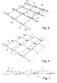
- FIG. 5 Depending on the size of the solar modules to be laid, which may be, for example photovoltaic modules, a plurality of mounting rails 17 may be mounted on a substructure in series and in parallel, as shown FIG. 5 is apparent. At this support rails 17 then the completed support elements 1 can be screwed or clamped and the Lucasableitbleche 21 are installed. Furthermore, to avoid a lateral air inlet side plates 23 may be attached to the support elements 1.
- FIG. 6 On the pre-assembled recording construction, as out FIG. 6 it can be seen, the solar modules 5 placed and in the manner described z. B. fastened by means of angle bracket 19. The individual solar modules 5 are spaced from each other, so that parts of the roof 25 are visible.
- FIG. 7 is a flat roof shown on the support elements according to FIGS. 1 to 4 are applied.
- FIG. 8 is an isometric view of an embodiment of a support member 1 reproduced, the base member 2 is extendable.
- a series arrangement of four support elements 1, which are constructed the same, is in FIG. 11 additionally shown in an isometric view.
- the elements used are the same. It is a modular structure using plug-in elements that can be connected to each other.
- the support member 1 consists of the base member 2 and a height portion 13 which consists of a hollow profile.
- the base element 2, which consists of a rake-shaped hollow profile, has openings on both sides. In the right lower opening, a first fastening element 4 is inserted with a holding element 6 and anchored therein.
- the fastening element 4 has a construction which corresponds to that of the first fastening element 4 in FIG FIG.
- FIG. 10 is apparent.
- the peculiarity consists in the fact that a further holding element 6 is attached to this fastening element 4 below in series with the upper, so that this holding element 6 can be inserted into an extension section 26, which establishes a distance between the two adjacent support elements 1. It can be seen that the length of this extension section 26 defines the distance between the two adjacent support elements 1 arranged in series.
- FIG. 10 is Furthermore, it can be seen that the inclined surface of the fastening element 4 together with the back of the molded-on holding element 6 at the same time forms the Lagerungsanformung for receiving the module.
- FIG. 8 further shows that the base portion 2 is also connected to the extension portion 26.
- the ends of the base portion 2 and the connecting portion 26 fitted, while on the upwardly projecting holding element 6 of the height section 13 is attached, to which the second fastening element 11 with the downwardly projecting holding element 6 can be anchored, as shown in the FIG. 4 already described.
- the wind deflector plates and side plates can also be attached to this support structure for solar modules.
- FIG. 11 shows in a series arrangement of four support elements 1, which are plugged together with the means described above and can be handled in combination, since the composite is very light.
- the composite can be placed on a roof or attached to it. Also, according to FIG. 5 several such series arrangements to be installed in parallel in order to mount the solar modules can.
- FIG. 16 That in the FIGS. 12 to 16 shown supporting element 1 consists of a hollow section 34, which made FIG. 16 is clearly visible. It is a rectangular hollow section 34 made of aluminum, which is made thin-walled in the continuous casting. The wall thickness is for example, only 0.5 mm. Of course, even with continuous casting support struts may be introduced, whereby the hollow section 34 is divided into two or three tunnels or only in sections.
- 34 miter cuts 36 are introduced into the hollow profile thus produced, which limit the spacer 13.
- the miter cut 36 is introduced according to the installation angle of the side parts 37 and 13. Normally this is a 90 ° angle of attack, but this can also have other sizes, wherein both sections 37, 13 can run at different angles.
- the miter cut 36 extends from the upper side of the base section 2 to the upper side of the lower wall 35 of the tubular profile 34. It can be seen that the two lateral sections 37 and 13 are now bendable in a simple manner upwards and run in an angular position relative to the base section 2 which is predetermined by the miter angle 36. In the embodiment, this is a vertical arrangement of the sections 37 and 13, as from the FIGS. 12 and 13 is apparent.
- the fastening sections 39 and 40 are cut free and further miter cuts 41 and 42 are introduced, which define the lateral sections, namely the fastening sections 39 and 40.
- attachment portions 39, 40 are what the FIGS. 12 and 14 can be seen, slot-shaped mounting recesses 47 and apertures incorporated, which are provided at least in the upper wall, which conform to the hollow section 34 according to FIG. 16 located at the bottom.
- nut holder or clamp body can be used, are screwed into the screws, with the help of holders on the mounting portions 39 and 40 are fastened, which alstypden on the frame and to be fastened solar modules can be fastened.
- the tube profile 34 according to FIG. 16 is bent after cutting and the introduction of miter cuts 36, 41 and 22 and welded by an automatic machine to the abutting side walls of Miter cuts, so that from FIG. 12 formed in the isometric representation support element 1 is formed.
- the mounting portions 39 and 40 are kept relatively short in order to save material.
- the structure is, however, bulky and so easily self-supporting on a roof and yet very light, since it is made of a thin-walled tube section 34.
- Positioning aids and stops are attached in a special way, which are cut free from the sheet metal wall of the hollow profile 34 and automatically set up when bending the height sections 37, 13.
- For the preparation of serving as a positioning aid tabs 44 they are cut free from the bottom wall 35 of the base portion 2, so that they automatically stand up when bending the sections 37 and 13.
- the tabs 44 are dimensioned so that their width corresponds to the clear width of the longitudinal slot 33 of the support rail 17 so that the support member 1 is simply placed aligned with this.
- the bore 45 in the upper wall of the base portion is made larger than the bore 46 in the lower wall 35, so that a screw with its screw head can be screwed down to the lower wall 35 and a connection takes place only on the lower wall of the support element 1 ,
- a screw with its screw head can be screwed down to the lower wall 35 and a connection takes place only on the lower wall of the support element 1 .
- slots are used in the latching clamping body to allow a fixation on the support rail 17.
- An example of this is the DE 20 2010 000 545 U1 refer to.
- FIG. 17 shows a support rail 17 with a C-profile 33 on the lateral attachment strip 31 with holes 30 for fixing to a roof by means of screws.
Landscapes
- Engineering & Computer Science (AREA)
- Chemical & Material Sciences (AREA)
- Life Sciences & Earth Sciences (AREA)
- Sustainable Development (AREA)
- Sustainable Energy (AREA)
- Thermal Sciences (AREA)
- Physics & Mathematics (AREA)
- Combustion & Propulsion (AREA)
- Mechanical Engineering (AREA)
- General Engineering & Computer Science (AREA)
- Architecture (AREA)
- Civil Engineering (AREA)
- Structural Engineering (AREA)
- Roof Covering Using Slabs Or Stiff Sheets (AREA)
Applications Claiming Priority (2)
| Application Number | Priority Date | Filing Date | Title |
|---|---|---|---|
| DE202011050810U DE202011050810U1 (de) | 2011-07-26 | 2011-07-26 | Stützelement für eine Unterkonstruktion für ein Solarmodul |
| DE202011052032U DE202011052032U1 (de) | 2011-11-18 | 2011-11-18 | Stützelement für ein Solarmodul |
Publications (3)
| Publication Number | Publication Date |
|---|---|
| EP2554925A2 true EP2554925A2 (fr) | 2013-02-06 |
| EP2554925A3 EP2554925A3 (fr) | 2013-07-31 |
| EP2554925B1 EP2554925B1 (fr) | 2015-05-20 |
Family
ID=46679129
Family Applications (1)
| Application Number | Title | Priority Date | Filing Date |
|---|---|---|---|
| EP20120177838 Not-in-force EP2554925B1 (fr) | 2011-07-26 | 2012-07-25 | Élément d'appui pour un module solaire |
Country Status (1)
| Country | Link |
|---|---|
| EP (1) | EP2554925B1 (fr) |
Cited By (4)
| Publication number | Priority date | Publication date | Assignee | Title |
|---|---|---|---|---|
| US20150349700A1 (en) * | 2013-02-11 | 2015-12-03 | Jonathan Port | Modular strap mount for solar panels |
| EP3205953A1 (fr) * | 2016-02-15 | 2017-08-16 | Solarmaterial AG | Système de montage d'éléments tabulaires et système solaire comprenant un tel système de montage |
| US9897345B2 (en) | 2014-10-16 | 2018-02-20 | Savo-Solar Oy | Mounting support for at least one solar thermal collector |
| CN108282143A (zh) * | 2018-03-30 | 2018-07-13 | 南京晶伏新能源科技有限公司 | 一种便于安装的光伏支架 |
Citations (6)
| Publication number | Priority date | Publication date | Assignee | Title |
|---|---|---|---|---|
| US3159250A (en) | 1962-02-05 | 1964-12-01 | Wilson Bertram Arnold | Structural member |
| WO2009091238A1 (fr) | 2008-01-18 | 2009-07-23 | J. Van Walraven Holding B.V. | Moyen de fixation pour panneaux solaires |
| DE202009016269U1 (de) | 2009-12-01 | 2010-03-04 | Naundorf Gmbh | Tragelement zur Fixierung von Solarmodulen |
| DE202010001083U1 (de) | 2010-01-19 | 2010-03-25 | Hafenbahn Gmbh & Co. Kg | Vorrichtung zur Anordnung von Solarpaneelen und/oder Wärmekollektoren auf einem Untergrund |
| DE202010000545U1 (de) | 2009-04-28 | 2010-07-22 | Kumatec Sondermaschinenbau & Kunststoffverarbeitung Gmbh | Befestigungseinrichtung für einen Holm oder eine Leiste an einem C-Profil |
| DE202010006377U1 (de) | 2010-05-03 | 2010-08-05 | Abakus Solar Ag | Unterkonstruktion für Solaranlage |
Family Cites Families (2)
| Publication number | Priority date | Publication date | Assignee | Title |
|---|---|---|---|---|
| EP2108899A2 (fr) * | 2008-04-07 | 2009-10-14 | Deutsche Solar Werke GmbH & Co. KG | Système de montage |
| EP2327941A1 (fr) * | 2008-09-26 | 2011-06-01 | Lahora Cruz, Jorge Agustin | Structure modulaire de support pour panneaux solaires |
-
2012
- 2012-07-25 EP EP20120177838 patent/EP2554925B1/fr not_active Not-in-force
Patent Citations (6)
| Publication number | Priority date | Publication date | Assignee | Title |
|---|---|---|---|---|
| US3159250A (en) | 1962-02-05 | 1964-12-01 | Wilson Bertram Arnold | Structural member |
| WO2009091238A1 (fr) | 2008-01-18 | 2009-07-23 | J. Van Walraven Holding B.V. | Moyen de fixation pour panneaux solaires |
| DE202010000545U1 (de) | 2009-04-28 | 2010-07-22 | Kumatec Sondermaschinenbau & Kunststoffverarbeitung Gmbh | Befestigungseinrichtung für einen Holm oder eine Leiste an einem C-Profil |
| DE202009016269U1 (de) | 2009-12-01 | 2010-03-04 | Naundorf Gmbh | Tragelement zur Fixierung von Solarmodulen |
| DE202010001083U1 (de) | 2010-01-19 | 2010-03-25 | Hafenbahn Gmbh & Co. Kg | Vorrichtung zur Anordnung von Solarpaneelen und/oder Wärmekollektoren auf einem Untergrund |
| DE202010006377U1 (de) | 2010-05-03 | 2010-08-05 | Abakus Solar Ag | Unterkonstruktion für Solaranlage |
Cited By (5)
| Publication number | Priority date | Publication date | Assignee | Title |
|---|---|---|---|---|
| US20150349700A1 (en) * | 2013-02-11 | 2015-12-03 | Jonathan Port | Modular strap mount for solar panels |
| US9742347B2 (en) * | 2013-02-11 | 2017-08-22 | Jonathan Port | Modular strap mount for solar panels |
| US9897345B2 (en) | 2014-10-16 | 2018-02-20 | Savo-Solar Oy | Mounting support for at least one solar thermal collector |
| EP3205953A1 (fr) * | 2016-02-15 | 2017-08-16 | Solarmaterial AG | Système de montage d'éléments tabulaires et système solaire comprenant un tel système de montage |
| CN108282143A (zh) * | 2018-03-30 | 2018-07-13 | 南京晶伏新能源科技有限公司 | 一种便于安装的光伏支架 |
Also Published As
| Publication number | Publication date |
|---|---|
| EP2554925A3 (fr) | 2013-07-31 |
| EP2554925B1 (fr) | 2015-05-20 |
Similar Documents
| Publication | Publication Date | Title |
|---|---|---|
| EP3683960B1 (fr) | Installation photovoltaïque | |
| DE202011050810U1 (de) | Stützelement für eine Unterkonstruktion für ein Solarmodul | |
| DE102013207827B4 (de) | Vorrichtung zum Befestigen von Solarmodulen und Dach | |
| DE102009019548A1 (de) | Aufstellmodul und Aufstellsystem für Sonnenkollektoren | |
| DE202009005741U1 (de) | Halterung für Unterkonstruktion von Solarmodulen sowie Unterkonstruktion von Solarmodulen | |
| EP1734588B1 (fr) | Recouvrement de toiture | |
| EP2317246B1 (fr) | Cadre en plusieurs parties pour module en forme de plaque | |
| DE202009004269U1 (de) | Halterung für Solarmodule zur Aufstellung auf einer Aufstellfläche | |
| EP2385323A2 (fr) | Châssis de fixation de modules solaires | |
| AT405313B (de) | Fassadenkonstruktion | |
| EP3978825B1 (fr) | Dispositif de support des modules solaires, kit, procédé de fabrication et agencement de module solaire | |
| CH718395B1 (de) | Haltevorrichtung für Solarmodule. | |
| EP2913606B1 (fr) | Système support pour un panneau solaire | |
| EP2554925B1 (fr) | Élément d'appui pour un module solaire | |
| DE102013216173A1 (de) | Anordnung und Verfahren zur Halterung mindestens eines Photovoltaikmoduls | |
| EP2423622B1 (fr) | Dispositif de fixation avec éléments de montage et rail de support | |
| DE102012108138A1 (de) | Trägerelement für ein Solarmodul, Trägersystem, Solaranlage und Verfahren zur Herstellung eines Trägerelements und/oder Trägersystems | |
| DE102011053774A1 (de) | Klemmelement für ein Befestigungssystem für plattenförmige Elemente, Befestigungssystem, das ein derartiges Klemmelement umfasst, sowie dessen Verwendung | |
| EP2400238A2 (fr) | Elévation d'un module solaire | |
| DE202011052032U1 (de) | Stützelement für ein Solarmodul | |
| WO2024046541A1 (fr) | Dispositif de support pour un système solaire et procédé de montage d'un système solaire | |
| DE9407701U1 (de) | Bausatz zur Halterung einer aus Platten, insbesondere Glasplatten o.dgl. zusammensetzbaren Fassade oder Dacheindeckung | |
| DE202010017971U1 (de) | Vorrichtung zum Abstützen von Solarmodulen | |
| EP1647649A2 (fr) | Système de fixation de façades | |
| EP3715745B1 (fr) | Système de fixation pour un système de module solaire hybride ainsi que système de module solaire hybride et procédé de fixation |
Legal Events
| Date | Code | Title | Description |
|---|---|---|---|
| PUAI | Public reference made under article 153(3) epc to a published international application that has entered the european phase |
Free format text: ORIGINAL CODE: 0009012 |
|
| AK | Designated contracting states |
Kind code of ref document: A2 Designated state(s): AL AT BE BG CH CY CZ DE DK EE ES FI FR GB GR HR HU IE IS IT LI LT LU LV MC MK MT NL NO PL PT RO RS SE SI SK SM TR |
|
| AX | Request for extension of the european patent |
Extension state: BA ME |
|
| PUAL | Search report despatched |
Free format text: ORIGINAL CODE: 0009013 |
|
| AK | Designated contracting states |
Kind code of ref document: A3 Designated state(s): AL AT BE BG CH CY CZ DE DK EE ES FI FR GB GR HR HU IE IS IT LI LT LU LV MC MK MT NL NO PL PT RO RS SE SI SK SM TR |
|
| AX | Request for extension of the european patent |
Extension state: BA ME |
|
| RIC1 | Information provided on ipc code assigned before grant |
Ipc: F24J 2/46 20060101ALI20130626BHEP Ipc: F24J 2/52 20060101AFI20130626BHEP |
|
| 17P | Request for examination filed |
Effective date: 20140131 |
|
| RBV | Designated contracting states (corrected) |
Designated state(s): AL AT BE BG CH CY CZ DE DK EE ES FI FR GB GR HR HU IE IS IT LI LT LU LV MC MK MT NL NO PL PT RO RS SE SI SK SM TR |
|
| 17Q | First examination report despatched |
Effective date: 20140704 |
|
| RIC1 | Information provided on ipc code assigned before grant |
Ipc: H01L 31/048 20140101ALI20140901BHEP Ipc: F24J 2/52 20060101AFI20140901BHEP Ipc: F24J 2/46 20060101ALI20140901BHEP Ipc: H01L 31/042 20140101ALI20140901BHEP |
|
| GRAP | Despatch of communication of intention to grant a patent |
Free format text: ORIGINAL CODE: EPIDOSNIGR1 |
|
| INTG | Intention to grant announced |
Effective date: 20141209 |
|
| GRAS | Grant fee paid |
Free format text: ORIGINAL CODE: EPIDOSNIGR3 |
|
| GRAA | (expected) grant |
Free format text: ORIGINAL CODE: 0009210 |
|
| AK | Designated contracting states |
Kind code of ref document: B1 Designated state(s): AL AT BE BG CH CY CZ DE DK EE ES FI FR GB GR HR HU IE IS IT LI LT LU LV MC MK MT NL NO PL PT RO RS SE SI SK SM TR |
|
| REG | Reference to a national code |
Ref country code: GB Ref legal event code: FG4D Free format text: NOT ENGLISH |
|
| REG | Reference to a national code |
Ref country code: CH Ref legal event code: EP |
|
| REG | Reference to a national code |
Ref country code: AT Ref legal event code: REF Ref document number: 727936 Country of ref document: AT Kind code of ref document: T Effective date: 20150615 |
|
| REG | Reference to a national code |
Ref country code: IE Ref legal event code: FG4D Free format text: LANGUAGE OF EP DOCUMENT: GERMAN |
|
| REG | Reference to a national code |
Ref country code: DE Ref legal event code: R096 Ref document number: 502012003188 Country of ref document: DE |
|
| RAP2 | Party data changed (patent owner data changed or rights of a patent transferred) |
Owner name: PREMIUM MOUNTING TECHNOLOGIES GMBH & CO. KG |
|
| REG | Reference to a national code |
Ref country code: LT Ref legal event code: MG4D |
|
| REG | Reference to a national code |
Ref country code: NL Ref legal event code: MP Effective date: 20150520 |
|
| PG25 | Lapsed in a contracting state [announced via postgrant information from national office to epo] |
Ref country code: FI Free format text: LAPSE BECAUSE OF FAILURE TO SUBMIT A TRANSLATION OF THE DESCRIPTION OR TO PAY THE FEE WITHIN THE PRESCRIBED TIME-LIMIT Effective date: 20150520 Ref country code: HR Free format text: LAPSE BECAUSE OF FAILURE TO SUBMIT A TRANSLATION OF THE DESCRIPTION OR TO PAY THE FEE WITHIN THE PRESCRIBED TIME-LIMIT Effective date: 20150520 Ref country code: LT Free format text: LAPSE BECAUSE OF FAILURE TO SUBMIT A TRANSLATION OF THE DESCRIPTION OR TO PAY THE FEE WITHIN THE PRESCRIBED TIME-LIMIT Effective date: 20150520 Ref country code: PT Free format text: LAPSE BECAUSE OF FAILURE TO SUBMIT A TRANSLATION OF THE DESCRIPTION OR TO PAY THE FEE WITHIN THE PRESCRIBED TIME-LIMIT Effective date: 20150921 Ref country code: ES Free format text: LAPSE BECAUSE OF FAILURE TO SUBMIT A TRANSLATION OF THE DESCRIPTION OR TO PAY THE FEE WITHIN THE PRESCRIBED TIME-LIMIT Effective date: 20150520 Ref country code: NO Free format text: LAPSE BECAUSE OF FAILURE TO SUBMIT A TRANSLATION OF THE DESCRIPTION OR TO PAY THE FEE WITHIN THE PRESCRIBED TIME-LIMIT Effective date: 20150820 |
|
| PG25 | Lapsed in a contracting state [announced via postgrant information from national office to epo] |
Ref country code: RS Free format text: LAPSE BECAUSE OF FAILURE TO SUBMIT A TRANSLATION OF THE DESCRIPTION OR TO PAY THE FEE WITHIN THE PRESCRIBED TIME-LIMIT Effective date: 20150520 Ref country code: LV Free format text: LAPSE BECAUSE OF FAILURE TO SUBMIT A TRANSLATION OF THE DESCRIPTION OR TO PAY THE FEE WITHIN THE PRESCRIBED TIME-LIMIT Effective date: 20150520 Ref country code: IS Free format text: LAPSE BECAUSE OF FAILURE TO SUBMIT A TRANSLATION OF THE DESCRIPTION OR TO PAY THE FEE WITHIN THE PRESCRIBED TIME-LIMIT Effective date: 20150920 Ref country code: GR Free format text: LAPSE BECAUSE OF FAILURE TO SUBMIT A TRANSLATION OF THE DESCRIPTION OR TO PAY THE FEE WITHIN THE PRESCRIBED TIME-LIMIT Effective date: 20150821 Ref country code: BG Free format text: LAPSE BECAUSE OF FAILURE TO SUBMIT A TRANSLATION OF THE DESCRIPTION OR TO PAY THE FEE WITHIN THE PRESCRIBED TIME-LIMIT Effective date: 20150820 |
|
| PG25 | Lapsed in a contracting state [announced via postgrant information from national office to epo] |
Ref country code: EE Free format text: LAPSE BECAUSE OF FAILURE TO SUBMIT A TRANSLATION OF THE DESCRIPTION OR TO PAY THE FEE WITHIN THE PRESCRIBED TIME-LIMIT Effective date: 20150520 Ref country code: DK Free format text: LAPSE BECAUSE OF FAILURE TO SUBMIT A TRANSLATION OF THE DESCRIPTION OR TO PAY THE FEE WITHIN THE PRESCRIBED TIME-LIMIT Effective date: 20150520 |
|
| REG | Reference to a national code |
Ref country code: DE Ref legal event code: R097 Ref document number: 502012003188 Country of ref document: DE |
|
| PG25 | Lapsed in a contracting state [announced via postgrant information from national office to epo] |
Ref country code: PL Free format text: LAPSE BECAUSE OF FAILURE TO SUBMIT A TRANSLATION OF THE DESCRIPTION OR TO PAY THE FEE WITHIN THE PRESCRIBED TIME-LIMIT Effective date: 20150520 Ref country code: RO Free format text: LAPSE BECAUSE OF NON-PAYMENT OF DUE FEES Effective date: 20150520 Ref country code: SK Free format text: LAPSE BECAUSE OF FAILURE TO SUBMIT A TRANSLATION OF THE DESCRIPTION OR TO PAY THE FEE WITHIN THE PRESCRIBED TIME-LIMIT Effective date: 20150520 Ref country code: CZ Free format text: LAPSE BECAUSE OF FAILURE TO SUBMIT A TRANSLATION OF THE DESCRIPTION OR TO PAY THE FEE WITHIN THE PRESCRIBED TIME-LIMIT Effective date: 20150520 Ref country code: MC Free format text: LAPSE BECAUSE OF FAILURE TO SUBMIT A TRANSLATION OF THE DESCRIPTION OR TO PAY THE FEE WITHIN THE PRESCRIBED TIME-LIMIT Effective date: 20150520 |
|
| REG | Reference to a national code |
Ref country code: CH Ref legal event code: PL |
|
| PLBE | No opposition filed within time limit |
Free format text: ORIGINAL CODE: 0009261 |
|
| STAA | Information on the status of an ep patent application or granted ep patent |
Free format text: STATUS: NO OPPOSITION FILED WITHIN TIME LIMIT |
|
| PG25 | Lapsed in a contracting state [announced via postgrant information from national office to epo] |
Ref country code: LU Free format text: LAPSE BECAUSE OF FAILURE TO SUBMIT A TRANSLATION OF THE DESCRIPTION OR TO PAY THE FEE WITHIN THE PRESCRIBED TIME-LIMIT Effective date: 20150725 |
|
| REG | Reference to a national code |
Ref country code: IE Ref legal event code: MM4A |
|
| 26N | No opposition filed |
Effective date: 20160223 |
|
| PG25 | Lapsed in a contracting state [announced via postgrant information from national office to epo] |
Ref country code: LI Free format text: LAPSE BECAUSE OF NON-PAYMENT OF DUE FEES Effective date: 20150731 Ref country code: CH Free format text: LAPSE BECAUSE OF NON-PAYMENT OF DUE FEES Effective date: 20150731 Ref country code: IT Free format text: LAPSE BECAUSE OF FAILURE TO SUBMIT A TRANSLATION OF THE DESCRIPTION OR TO PAY THE FEE WITHIN THE PRESCRIBED TIME-LIMIT Effective date: 20150520 |
|
| REG | Reference to a national code |
Ref country code: FR Ref legal event code: ST Effective date: 20160331 |
|
| PG25 | Lapsed in a contracting state [announced via postgrant information from national office to epo] |
Ref country code: SI Free format text: LAPSE BECAUSE OF FAILURE TO SUBMIT A TRANSLATION OF THE DESCRIPTION OR TO PAY THE FEE WITHIN THE PRESCRIBED TIME-LIMIT Effective date: 20150520 Ref country code: FR Free format text: LAPSE BECAUSE OF NON-PAYMENT OF DUE FEES Effective date: 20150731 |
|
| PG25 | Lapsed in a contracting state [announced via postgrant information from national office to epo] |
Ref country code: IE Free format text: LAPSE BECAUSE OF NON-PAYMENT OF DUE FEES Effective date: 20150725 |
|
| GBPC | Gb: european patent ceased through non-payment of renewal fee |
Effective date: 20160725 |
|
| PG25 | Lapsed in a contracting state [announced via postgrant information from national office to epo] |
Ref country code: MT Free format text: LAPSE BECAUSE OF FAILURE TO SUBMIT A TRANSLATION OF THE DESCRIPTION OR TO PAY THE FEE WITHIN THE PRESCRIBED TIME-LIMIT Effective date: 20150520 |
|
| PG25 | Lapsed in a contracting state [announced via postgrant information from national office to epo] |
Ref country code: GB Free format text: LAPSE BECAUSE OF NON-PAYMENT OF DUE FEES Effective date: 20160725 Ref country code: SM Free format text: LAPSE BECAUSE OF FAILURE TO SUBMIT A TRANSLATION OF THE DESCRIPTION OR TO PAY THE FEE WITHIN THE PRESCRIBED TIME-LIMIT Effective date: 20150520 Ref country code: HU Free format text: LAPSE BECAUSE OF FAILURE TO SUBMIT A TRANSLATION OF THE DESCRIPTION OR TO PAY THE FEE WITHIN THE PRESCRIBED TIME-LIMIT; INVALID AB INITIO Effective date: 20120725 |
|
| PG25 | Lapsed in a contracting state [announced via postgrant information from national office to epo] |
Ref country code: NL Free format text: LAPSE BECAUSE OF FAILURE TO SUBMIT A TRANSLATION OF THE DESCRIPTION OR TO PAY THE FEE WITHIN THE PRESCRIBED TIME-LIMIT Effective date: 20150520 Ref country code: CY Free format text: LAPSE BECAUSE OF FAILURE TO SUBMIT A TRANSLATION OF THE DESCRIPTION OR TO PAY THE FEE WITHIN THE PRESCRIBED TIME-LIMIT Effective date: 20150520 Ref country code: SE Free format text: LAPSE BECAUSE OF FAILURE TO SUBMIT A TRANSLATION OF THE DESCRIPTION OR TO PAY THE FEE WITHIN THE PRESCRIBED TIME-LIMIT Effective date: 20150520 |
|
| PG25 | Lapsed in a contracting state [announced via postgrant information from national office to epo] |
Ref country code: BE Free format text: LAPSE BECAUSE OF NON-PAYMENT OF DUE FEES Effective date: 20150731 |
|
| PG25 | Lapsed in a contracting state [announced via postgrant information from national office to epo] |
Ref country code: TR Free format text: LAPSE BECAUSE OF FAILURE TO SUBMIT A TRANSLATION OF THE DESCRIPTION OR TO PAY THE FEE WITHIN THE PRESCRIBED TIME-LIMIT Effective date: 20150520 |
|
| PGFP | Annual fee paid to national office [announced via postgrant information from national office to epo] |
Ref country code: DE Payment date: 20170511 Year of fee payment: 6 |
|
| REG | Reference to a national code |
Ref country code: DE Ref legal event code: R079 Ref document number: 502012003188 Country of ref document: DE Free format text: PREVIOUS MAIN CLASS: F24J0002520000 Ipc: F24S0025000000 |
|
| PGFP | Annual fee paid to national office [announced via postgrant information from national office to epo] |
Ref country code: AT Payment date: 20170727 Year of fee payment: 6 |
|
| PG25 | Lapsed in a contracting state [announced via postgrant information from national office to epo] |
Ref country code: MK Free format text: LAPSE BECAUSE OF FAILURE TO SUBMIT A TRANSLATION OF THE DESCRIPTION OR TO PAY THE FEE WITHIN THE PRESCRIBED TIME-LIMIT Effective date: 20150520 |
|
| PG25 | Lapsed in a contracting state [announced via postgrant information from national office to epo] |
Ref country code: AL Free format text: LAPSE BECAUSE OF FAILURE TO SUBMIT A TRANSLATION OF THE DESCRIPTION OR TO PAY THE FEE WITHIN THE PRESCRIBED TIME-LIMIT Effective date: 20150520 |
|
| REG | Reference to a national code |
Ref country code: DE Ref legal event code: R119 Ref document number: 502012003188 Country of ref document: DE |
|
| REG | Reference to a national code |
Ref country code: AT Ref legal event code: MM01 Ref document number: 727936 Country of ref document: AT Kind code of ref document: T Effective date: 20180725 |
|
| PG25 | Lapsed in a contracting state [announced via postgrant information from national office to epo] |
Ref country code: AT Free format text: LAPSE BECAUSE OF NON-PAYMENT OF DUE FEES Effective date: 20180725 Ref country code: DE Free format text: LAPSE BECAUSE OF NON-PAYMENT OF DUE FEES Effective date: 20190201 |