EP2554982A1 - Biosensor - Google Patents
Biosensor Download PDFInfo
- Publication number
- EP2554982A1 EP2554982A1 EP11765650A EP11765650A EP2554982A1 EP 2554982 A1 EP2554982 A1 EP 2554982A1 EP 11765650 A EP11765650 A EP 11765650A EP 11765650 A EP11765650 A EP 11765650A EP 2554982 A1 EP2554982 A1 EP 2554982A1
- Authority
- EP
- European Patent Office
- Prior art keywords
- reaction layer
- reaction
- layer
- biosensor
- sample
- Prior art date
- Legal status (The legal status is an assumption and is not a legal conclusion. Google has not performed a legal analysis and makes no representation as to the accuracy of the status listed.)
- Granted
Links
Images




Classifications
-
- G—PHYSICS
- G01—MEASURING; TESTING
- G01N—INVESTIGATING OR ANALYSING MATERIALS BY DETERMINING THEIR CHEMICAL OR PHYSICAL PROPERTIES
- G01N27/00—Investigating or analysing materials by the use of electric, electrochemical, or magnetic means
- G01N27/26—Investigating or analysing materials by the use of electric, electrochemical, or magnetic means by investigating electrochemical variables; by using electrolysis or electrophoresis
- G01N27/28—Electrolytic cell components
- G01N27/30—Electrodes, e.g. test electrodes; Half-cells
- G01N27/327—Biochemical electrodes, e.g. electrical or mechanical details for in vitro measurements
- G01N27/3271—Amperometric enzyme electrodes for analytes in body fluids, e.g. glucose in blood
- G01N27/3272—Test elements therefor, i.e. disposable laminated substrates with electrodes, reagent and channels
-
- C—CHEMISTRY; METALLURGY
- C12—BIOCHEMISTRY; BEER; SPIRITS; WINE; VINEGAR; MICROBIOLOGY; ENZYMOLOGY; MUTATION OR GENETIC ENGINEERING
- C12Q—MEASURING OR TESTING PROCESSES INVOLVING ENZYMES, NUCLEIC ACIDS OR MICROORGANISMS; COMPOSITIONS OR TEST PAPERS THEREFOR; PROCESSES OF PREPARING SUCH COMPOSITIONS; CONDITION-RESPONSIVE CONTROL IN MICROBIOLOGICAL OR ENZYMOLOGICAL PROCESSES
- C12Q1/00—Measuring or testing processes involving enzymes, nucleic acids or microorganisms; Compositions therefor; Processes of preparing such compositions
- C12Q1/001—Enzyme electrodes
- C12Q1/005—Enzyme electrodes involving specific analytes or enzymes
-
- G—PHYSICS
- G01—MEASURING; TESTING
- G01N—INVESTIGATING OR ANALYSING MATERIALS BY DETERMINING THEIR CHEMICAL OR PHYSICAL PROPERTIES
- G01N33/00—Investigating or analysing materials by specific methods not covered by groups G01N1/00 - G01N31/00
- G01N33/48—Biological material, e.g. blood, urine; Haemocytometers
- G01N33/483—Physical analysis of biological material
Definitions
- the present invention relates to biosensor, in particular, biosensor for measuring concentration of neutral fat.
- the invention relates specifically to a biosensor capable of determining the concentration of a specific component in a specific sample, such as living body sample, quantitatively and rapidly by use of enzyme reaction, in particular, such a biosensor for measuring the concentration of neutral fat.
- biosensors have been used in the field of medicine and others.
- Targets to be measured by biosensors are various chemical substances, examples of which include low molecular weight and high molecular weight molecules.
- the development of a biosensor having various functions has been advanced.
- biosensors have been known which can easily attain quantitative determination without diluting or stirring a specific component (substrate) contained in living body sample, or food.
- a biosensor obtained by: forming an electrode system having at least a working electrode and a counter electrode on an insulating base plate; laying, onto this electrode system, an enzyme reaction layer containing a redox enzyme and an electron receptor each immobilized with an immobilizing agent such as a hydrophilic polymer; next laying a filtrating layer (blood corpuscle removing layer) onto this enzyme reaction layer; and further covering this filtrating layer, from the above, with a cover to integrate these members into a unit.
- the concentration of substrate in a sample is quantitatively determined in the following manner: First, a sample solution, such as blood, is dropped onto the filtrating layer, and the resultant filtrate penetrates into the enzyme reaction layer. In this way, the redox enzyme and the electron receptor are dissolved in the sample solution so that an enzyme reaction advances between the substrate and the enzyme. By this enzyme reaction, the substrate is oxidized and simultaneously the electron receptor is reduced. After the enzyme reaction ends, the reduced electron receptor is electrochemically oxidized. From the oxidation current value obtained at this time, the concentration of the substrate in the sample solution can be calculated.
- a method for measuring neutral fat with biosensor known is, for example, a method of determining neutral fat in sample quantitatively as follows: the neutral fat contained in sample solution is first decomposed into, for example, free fatty acid and glycerol with lipoprotein lipase (LPL) .
- LPL lipoprotein lipase
- glycerol generated therein can be quantitatively determined, using glycerol kinase (GK), and glycerol-3-phosphoric acid oxidase (GPO), or glycerol-3-phosphoric acid dehydrogenase (GPDH).
- GK glycerol kinase
- GPO glycerol-3-phosphoric acid oxidase
- GPDH glycerol-3-phosphoric acid dehydrogenase
- the glycerol can be quantitatively determined by measuring decrease in the oxidized-form electron receptor, increase in the reduced-form electron receptor, or the quantity of dihydroxyacetone phosphoric acid, as shown in the following formulae. In particular, by measuring the quantity of the increase in the reduced-form electron receptor electrochemically, the glycerol can be quantitatively determined.
- LPL lipoprotein lipase
- GK glycerol kinase
- GPO glycerol-3-phosphoric acid oxidase
- Patent Literature 1 a biosensor, in which, as enzymes used in a decomposition reaction of neutral fat, two of neutral fat decomposing enzyme and glycerol dehydrogenase (GLDH) are used to decrease enzyme costs, is disclosed (Patent Literature 1) .
- the biosensor of Patent Literature 1 is not sufficient about the measurement time, and in precision. Thus, it is desired to make the precision higher, and make the measurement more rapidly.
- NAD-GLDH NAD+ dependent glycerol dehydrogenase
- Patent Literatures 2 and 3 in order to supply a biosensor capable of measuring neutral fat with high precision in short time, reports have been hitherto made about biosensors in each of which a neutral fat decomposing enzyme and glycerol dehydrogenase are located in different layers, respectively (Patent Literatures 2 and 3).
- the biosensor of Patent Literature 2 has a structure having, on an electrode, a polymer layer containing GLDH and a hydrophilic polymer, and a filter layer containing a neutral fat decomposing enzyme carried on a filter paper, these two reaction layers being laminated in turn .
- the biosensor of Patent Literature 3 is characterized by having a structure having, on an electrode, a polymer layer containing GLDH and a hydrophilic polymer, and a nonwoven cloth layer containing a neutral fat decomposing enzyme carried on a nonwoven cloth, these two reaction layers being laminated in turn.
- the measuring time is two minutes in Example (paragraph [0100] of Patent Literature 2, and paragraph [0100] of Patent Literature 3). In conclusion, the measuring time is not yet sufficiently short. Thus, a biosensor capable of making a measurement in a shorter time is desired.
- the invention has been made to solve the problems, and an object thereof is to provide a biosensor capable of measuring the concentration of a specific component, such as neutral fat, in sample in a short period.
- the inventors have eagerly made researches to solve the problems. As a result, the inventors have found that when a reaction layer is made into a bilayered structure, without using a carrier such as a filter paper or a nonwoven cloth, by the formation of a lipid-decomposing-enzyme-containing layer on a redox-enzyme-containing layer by applying a lipid-decomposing-enzyme-containing solution directly onto the redox-enzyme-containing layer, the rates of reactions by the two enzymes can be improved. Based on this finding, the invention has been achieved.
- a biosensor comprising an insulating base plate, an electrode system containing at least a working electrode and a counter electrode and formed on the insulating base plate, and a sample-supplying section formed on the electrode system, wherein the sample-supplying section has a reaction layer comprising: a first reaction layer formed on the electrode system and containing at least a redox enzyme into which pyrroloquinoline quinone (PQQ), flavin adenine dinucleotide (FAD), or flavin mononucleotide (FMN) is incorporated as a prosthetic group; and a second reaction layer formed by applying, onto the first reaction layer, a solution including a lipid decomposing enzyme.
- PQQ pyrroloquinoline quinone
- FAD flavin adenine dinucleotide
- FMN flavin mononucleotide
- biosensor of the invention makes it possible to measure the concentration of target component in a short period.
- a biosensor comprising an insulating base plate, an electrode system containing at least a working electrode and a counter electrode and formed on the insulating base plate, and a sample-supplying section formed on the electrode system, wherein the sample-supplying section has a reaction layer including: a first reaction layer formed on the electrode system and containing at least a redox enzyme including, as a prosthetic group, pyrroloquinoline quinone (PQQ), flavin adenine dinucleotide (FAD), or flavin mononucleotide (FMN) (in the specification, the layer may be referred to merely as "first reaction layer”); and a second reaction layer formed by applying, onto the first reaction layer, a solution containing a lipid decomposing enzyme (in the specification, the layer may be referred to merely as "second reaction layer”) .
- a reaction layer including: a first reaction layer formed on the electrode system and containing at least a redox enzyme including, as a prosthetic group, pyrroloquino
- the invention is characterized in that the reaction layer is made into a bilayered structure including the redox-enzyme-containing first reaction layer and the lipid-decomposing-enzyme-containing second reaction layer, and, the second reaction layer is formed by applying a lipid-decomposing-enzyme-containing solution directly onto the first reaction layer.
- the redox enzyme such as glycerol dehydrogenase (GLDH)
- GLDH glycerol dehydrogenase
- a solution containing a lipid decomposing enzyme is applied onto the first reaction layer containing a redox enzyme to form the second reaction layer directly on the first reaction layer.
- Fig. 1 is an exploded perspective view illustrating one of the embodiments of the biosensor of the invention.
- Fig. 2 is a sectional view of the biosensor in Fig. 1 .
- the biosensor illustrated in Figs. 1 and 2 may be referred to as a "first biosensor".
- an electrode system including working electrode 2, reference electrode 3 and counter electrode 4 is formed on insulating base plate 1, which may be referred to merely as "base plate” in the specification.
- the electrode system needs to include at least a working electrode and a counter electrode.
- reference electrode 3 may be omitted.
- Layers of adhesive 6 are set on edges of the insulating base plate 1.
- the working electrode 2, the reference electrode 3 and the counter electrode 4 function as means for electrical connection of the biosensor.
- the working electrode 2, the reference electrode 3 and the counter electrode 4 may each be formed as an electrode having a desired pattern by appropriately referring to conventionally known findings, for example, about screen printing, sputtering or some other method, or by combining two or more thereof.
- An insulating layer 5 is formed on the working electrode 2, the reference electrode 3 and the counter electrode 4 each formed on the insulating base plate 1 to make the electrode system exposed.
- the insulating layer 5 functions as an insulating means to prevent a short circuit between the individual electrodes.
- the method to form the insulating layer is not particularly limited. Thus, the layer may be formed by a conventionally known method such as a screen printing method or a bonding method.
- Working region of working electrode 2-1, working region of reference electrode 3-1 and working region of counter electrode 4-1 are formed so as to sandwich insulating layer 5.
- a sample-supplying section is composed of the first reaction layer 8, the second reaction layer 9, and space S positioned between the second reaction layer 9 and cover 7.
- the first reaction layer 8 contains at least redox enzyme into which at least pyrroloquinoline quinone (PQQ), flavin adenine dinucleotide (FAD), or flavin mononucleotide (FMN) is incorporated as a prosthetic group (hereinafter, the redox enzyme may be referred to as the "redox enzyme in the invention”) .
- PQQ pyrroloquinoline quinone
- FAD flavin adenine dinucleotide
- FMN flavin mononucleotide
- the second reaction layer 9 is formed on the first reaction layer 8 and formed by applying at least a solution containing lipid decomposing enzyme thereonto.
- the second reaction layer is formed by applying a solution containing lipid decomposing enzyme means that a solution containing a lipid decomposing enzyme is applied directly onto the first reaction layer, without carrying the lipid decomposing enzyme by a carrier such as a filter paper or a nonwoven cloth, and then dried to form an applied film.
- the working regions (2-1, 3-1 and 4-1) function as a potential applying means to apply an electric potential to a sample in the first reaction layer 8, and a current detecting means to detect a current flow in the sample when the biosensor is used.
- the working electrode 2, the reference electrode 3 and the counter electrode 4 including the working regions (2-1, 3-1 and 4-1) , respectively, may be referred to as the working electrode 2, the reference electrode 3 and the counter electrode 4, respectively.
- the working electrode 2 and the counter electrode 4 work in the form of a pair when the biosensor is used, and function as a current measuring means to measure an oxidation current (response current) flowing when the potential is applied to the sample in the first reaction layer 8.
- the reference electrode 3 is used as a reference base to apply a predetermined potential to the counter electrode 4 and the working electrode 2 across these electrodes.
- the biosensor of the present embodiment is formed by bonding the cover 7 (onto the base plate 1) with the adhesive (double-sided tape) 6 laid on the base plate 1 to cover the first reaction layer 8 and the second reaction layer 9.
- the adhesive (double-sided tape) 6 may be laid on the electrode-side part, or only on the cover-7-side part, or may be laid on the both.
- the sample-supplying section further contains electron carrier.
- the electron carrier may be present in any embodiment inside the sample-supplying section.
- Specific examples of the embodiments include a embodiment (A) that the first reaction layer 8 contains electron carrier (electron carrier is located in the first reaction layer 8) ; an embodiment (B) that the second reaction layer 9 contains electron carrier (electron carrier is located in the second reaction layer 9) , and an embodiment (C) that a third reaction layer containing the electron carrier is further laid. Any one of these embodiments (A), (B) and (C) may be used, or two or more of the embodiments (A), (B) and (C) may be used in combination.
- the embodiment (B) or (C) is more preferred.
- the second reaction layer has electron carrier (electron carrier is located in the second reaction layer), or the biosensor further has a third reaction layer containing electron carrier.
- a layer containing a surfactant which may be referred to as surfactant layer hereinafter, is further located in the sample-supplying section to be separated from the first and second reaction layers 8 and 9.
- the arrangement of the surfactant layer is not particularly limited.
- the surfactant layer is formed on the cover side to be separated from the first and second reaction layer 8 and 9.
- the spread or wettability of a sample, such as whole-blood sample, onto the cover side is better than when the cover 7 directly contacts the sample.
- the third reaction layer which has electron carrier
- the third reaction layer is further located in the sample-supplying section to be separated from the first and second reaction layers 8 and 9.
- the arrangement of the third reaction layer is not particularly limited.
- the third reaction layer is formed on the cover side to be separated from the first and second reaction layer 8 and 9.
- a different embodiment of the biosensor of the invention in a case where the biosensor contains a third reaction layer is a biosensor including an insulating base plate, an electrode system containing at least a working electrode and a counter electrode and formed on the insulating base plate, and a sample-supplying section formed on the electrode system, wherein: the sample-supplying section has a reaction layer including a first reaction layer formed on the electrode system and containing at least a redox enzyme into which pyrroloquinoline quinone (PQQ), flavin adenine dinucleotide (FAD), or flavin mononucleotide (FMN) is incorporated as a prosthetic group; a second reaction layer formed by applying, onto the first reaction layer, a solution including a lipid decomposing enzyme; and further the third reaction layer containing an electron carrier is located to be separated from the first and second reaction layers.
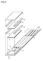
- the biosensor according to the different embodiment of the invention will be described with reference to Figs. 3 and 4 .
- Fig. 3 is an exploded perspective view illustrating the different embodiment of the biosensor of the invention, which contains a third reaction layer.
- Fig. 4 is a sectional view of the biosensor in Fig. 3 .
- the biosensor illustrated in Figs. 3 and 4 may be referred to as "second biosensor".
- a basic structure thereof is identical with that of the biosensor illustrated in Figs. 1 and 2 except that third reaction layer 10 containing electron carrier is further laid (specifically, third reaction layer 10 is located together with first reaction layer 8 and second reaction layer 9) .
- third reaction layer 10 a layer formed on cover 7 side
- first reaction layer 8 and second reaction layer 9 a layer nearer to its electrodes and the other layer
- the sample-supplying section is composed of the first, second and third reaction layers 8, 9 and 10, and space S arranged between the second reaction layer 9 and the third reaction layer 10.
- the first reaction layer 8 contains redox enzyme
- the second reaction layer 9 contains lipid decomposing enzyme
- the third reaction layer 10 contains electron carrier.
- the third reaction layer 10 is formed on the cover 7, which has two edges on which layers of adhesive (double-sided tape) 6a are located, respectively, to be arranged in a gap between the two edges.
- the second biosensor is formed by bonding adhesives (double-sided tapes) 6b bonded to base plate 1 on which the first and second reaction layers 8 and 9 are formed, and, the adhesives (double-sided tapes) 6a bonded to the cover 7 on which the first reaction layer 8 is formed, together.
- the adhesive (double-sided tape) 6 may be located only on the base plate 1 side, or may be located only on the cover 7 side.
- the structure of the first biosensor is identical with that of the second biosensor except that the secondbiosensor further has the third reaction layer 10; thus, any specific description about the structural requirements described below is applicable to the first and the second biosensors of the invention unless otherwise specified.
- the term “per sensor” may be used.
- the term “per sensor” means the following: for each sensor in which the volume of sample to be supplied to the sample-supplying section is "0.1 to 20 ⁇ l (preferably about 2 ⁇ l)", and the sensor size is the size of ordinary biosensors.
- the invention can be applied thereto by adjusting the contained amount of the each of the structural requirements appropriately.
- the insulating base plate 1 used in the invention is not particularly limited; thus, a conventionally known material may be used therefor. Examples thereof include plastics, papers, glasses, and ceramics.
- the shape and the size of the insulating base plate 1 are not particularly limited.
- the plastics are not particularly limited either, and may be conventional known ones. Examples thereof include polyethylene terephthalate (PET), polyesters, polystyrene, polypropylene, polycarbonates, polyimides, and acrylic resins.
- PET polyethylene terephthalate
- polyesters polystyrene, polypropylene
- polycarbonates polycarbonates
- polyimides polyimides
- acrylic resins acrylic resins
- the electrodes in the invention include at least the working electrode 2 and the counter electrode 4.
- the electrodes in the invention are not particularly limited as far as the electrodes are capable of detecting a reaction of the sample (the target to be measured) and the redox enzyme in the invention electrochemically.
- Examples thereof include carbon electrode, gold electrode, silver electrode, platinum electrode, and palladium electrode. From the viewpoint of corrosion resistance and costs, carbon electrodes are preferred.
- the electrodes maybe of a two-electrode type, which includes only the working electrode 2 and the counter electrode 4, or may be of a three-electrode type, which further includes the reference electrode 3.
- the three-electrode type may be more preferably used than the two-electrode type in order to attain potential-control with a higher sensitivity.
- the electrodes in the invention may include ther electrode such as a detecting electrode to detect the quantity of a liquid.
- a region thereof which contacts the sample-supplying section maybe made of a constitutingmaterial different from that of the other electrode regions.
- working region of reference electrode 3-1 may be made of silver/silver chloride. Since ordinary biosensors are disposable, it is advisable to use disposable electrodes as the electrodes.
- Material constituting insulating layer 5 is not particularly limited, and examples thereof include resist ink, resins such as PET and polyethylene, glass, ceramic, and paper.
- the material is preferably PET.
- the sample-supplying section has the first reaction layer 8, which contains redox enzyme, and the second reaction layer 9, which contains lipid decomposing enzyme.
- the sample-supplying section also has the surfactant layer.
- the sample-supplying section has not only the first reaction layer 8, which contains redox enzyme, and the second reaction layer 9, which contains lipid decomposing enzyme, but also the third reaction layer 10, which is formed separately from the first and second reaction layers 8 and 9, and the third reaction layer 9 contains electron carrier.
- the redox enzyme and the electron carrier can be included in different layers from each other, then, the biosensor can be prevented from being deteriorated by contact between the electron carrier and the redox enzyme when stored.
- the respective thicknesses of the first and second reaction layers 8 and 9 are not particularly limited, and may each be appropriately selected to be a thickness of ordinary reaction layers.
- the thickness of the first reaction layer 8 is preferably from 0.01 to 25 ⁇ m, more preferably from 0.025 to 10 ⁇ m, in particular preferably from 0.05 to 8 ⁇ m.
- the thickness of the second reaction layer 9 is preferably from 0.01 to 25 ⁇ m, more preferably from 0.025 to 10 ⁇ m, in particular preferably from 0.05 to 8 ⁇ m.
- the total thickness of the first and second reaction layers 8 and 9 is within a range preferably from 0.02 to 50 ⁇ m, more preferably from 0.05 to 20 ⁇ m, in particular preferably from 0.1 to 16 ⁇ m.
- the method to control each of the thicknesses is not particularly limited.
- the thickness can be controlled by adjusting appropriately the application quantity (for example, the dropping quantity) of the solution containing predetermined components.
- the thickness thereof is preferably from 0.01 to 25 ⁇ m, more preferably from 0.025 to 10 ⁇ m, even more preferably from 0.05 to 8 ⁇ m.
- the separation distance between the second reaction layer 9 and the surfactant layer is preferably from 0.05 to 1.5 mm, more preferably from 0.07 to 1.25 mm, even more preferably from 0.09 to 1 mm. When the distance is in this range, a capillary phenomenon is easily caused then a sample is easily introduced into the sample-supplying section.
- the thicknesses of the first and second reaction layers 8 and 9, and the optionally formed surfactant layer may be the same or different.
- the respective thicknesses of the first and second reaction layers 8 and 9 and the third reaction layer are not particularly limited, and may each be appropriately selected to be an ordinary reactionlayerthickness.
- the thickness of the first reaction layer 8 is preferably from 0.01 to 25 ⁇ m, more preferably from 0.025 to 10 ⁇ m, in particular preferably from 0.05 to 8 ⁇ m.
- the thickness of the second reaction layer 9 is preferably from 0.01 to 25 ⁇ m, more preferably from 0.025 to 10 ⁇ m, in particular preferably from 0.05 to 8 ⁇ m. It is advisable to set the total thickness of the first and second reaction layers 8 and 9 in a range preferably from 0.02 to 50 ⁇ m, more preferably from 0.05 to 20 ⁇ m, in particular preferably from 0.1 to 16 ⁇ m.
- the thickness of the third reaction layer 10 is within a range of preferably 0.01 to 10 ⁇ m, more preferably 0.025 to 10 ⁇ m, in particular preferably 0.05 to 8 ⁇ m.
- the respective thicknesses of the first, second and third reaction layers 8, 9 and 10 may be the same or different.
- the method to control each of the thicknesses is not particularly limited.
- the thickness can be controlled by adjusting appropriately the application quantity (for example, the dropping quantity) of a solution containing predetermined components.
- the separation distance between the second reaction layer 9 and the third reaction layer 10 is not particularly limited, and is preferably from 0.05 to 1.5 mm, more preferably from 0.075 to 1.25 mm, in particular preferably from 0.1 to 1 mm.
- the separation distance can be controlled by controlling the thickness of the adhesive.
- the adhesive also fulfills function of a spacer to separate the second reaction layer 9 and the third reaction layer 10 from each other.
- the first reaction layer 8 contains redox enzyme into which pyrroloquinoline quinone (PQQ), flavin adenine dinucleotide (FAD), or flavin mononucleotide (FMN) is incorporated as a prosthetic group, which may be referred to as "coenzyme".
- the redox enzyme is in particular preferably a polyoldehydrogenase into which pyrroloquinoline quinone (PQQ) is incorporated as a prosthetic group.
- PQQ pyrroloquinoline quinone
- PQQ flavin adenine dinucleotide
- FMN flavin mononucleotide
- the redox enzyme into which pyrroloquinoline quinone (PQQ), flavin adenine dinucleotide (FAD), or flavin mononucleotide (FMN) is incorporated as a prosthetic group, is not particularly limited, and is dependent on the kind of the sample.
- Examples of the redox enzyme into which pyrroloquinoline quinone (PQQ) is incorporated as a prosthetic group include glycerol dehydrogenase, sorbitol dehydrogenase, mannitol dehydrogenase, arabitol dehydrogenase, galactitol dehydrogenase, xylitol dehydrogenase, adonitol dehydrogenase, erythritol dehydrogenase, ribitol dehydrogenase, propylene glycol dehydrogenase, fructose dehydrogenase, glucose dehydrogenase, gluconic acid dehydrogenase, 2-ketogluconic acid dehydrogenase, 5 ketogluconic acid dehydrogenase, 2,5-diketogluconic acid dehydrogenase, alcohol dehydrogenase, cyclic alcohol dehydrogenase, acetoal
- Examples of the redox enzyme into which flavin adenine dinucleotide (FAD) or flavin mononucleotide (FMN) is incorporated as a prosthetic group include glucose oxidase, glucose dehydrogenase, D-amino acid oxidase, succinic acid dehydrogenase, monoamine oxidase, sarcosine dehydrogenase, glycerol dehydrogenase, sorbitol dehydrogenase, D-lactic acid dehydrogenase, and cholesterol oxidase.
- Preferred is glycerol dehydrogenase into which at least one of pyrroloquinoline quinone (PQQ) or flavin adenine dinucleotide (FAD) is incorporated as a prosthetic group, and particularly preferred is glycerol dehydrogenase into which pyrroloquinoline quinone (PQQ) is incorporated as a prosthetic group (hereinafter, this combination may be referred to as "PQQ-dependent glycerol dehydrogenase").
- PQQ pyrroloquinoline quinone
- FAD flavin adenine dinucleotide
- the redox enzyme in the invention may be a purchased commercially available product, or an enzyme prepared in person.
- the method for preparing the redox enzyme in person may be, for example, a known method of cultivating bacteria which can produce the redox enzyme in a nutrient medium, and then extracting the redox enzyme from the culture (see, for example, JP-A No. 2008-220367 ).
- PQQ-dependent glycerol dehydrogenase a specific example of bacteria which can produce the glycerol dehydrogenase includes bacteria belonging to various genera, such as Gluconobacter and Pseudomonas. It is particularly preferred to use PQQ-dependent glycerol dehydrogenase that is present in a membrane fraction of bacteria belonging to Gluconobacter.
- the medium for cultivating PQQ-dependent glycerol dehydrogenase may be a synthetic medium or a natural medium as far as the medium contains appropriate quantities of a carbon source, a nitrogen source, an inorganic substance and other necessary nutrients that can be utilized by a bacterial strain used.
- a carbon source include glucose, glycerol, and sorbitol.
- the nitrogen source include nitrogen-containingnatural products such as peptones, meat extracts and yeast extracts; and nitrogen-containing inorganic substances such as ammonium chloride, and ammonium citrate.
- Usable examples of the inorganic substances include potassium phosphate, sodium phosphate, and magnesium sulfate. Additionally, specific vitamins may be optionally used.
- the above-mentioned carbon sources, as well as the nitrogen sources, the inorganic substances, or other necessary nutrients may be used alone or in combination of two or more thereof.
- the cultivation is preferably shaking cultivation, or aerated mixing cultivation.
- the cultivating temperature is preferably 20 to 50°C, more preferably 22 to 40°C, most preferably 25 to 35°C.
- the cultivating pH is preferably 4 to 9, more preferably 5 to 8. Conditions other than these conditions are permissible as far as the bacterial strain used grows. Usually, the cultivation period is preferably 0.5 to 5 days.
- a redox enzyme is accumulated in bacterial cells.
- the redox enzyme may be an enzyme obtained by the cultivation, or a recombinant enzyme obtained by transducing genes of the redox enzyme into colon bacillus or other bacteria.
- the method for the extraction may be an ordinarily used extracting method, examples of which include an ultrasonic fracturing method, a French pressing method, an organic solvent method, and a lysozyme method.
- the method to purify the extracted redox enzyme is not particularly limited, and may be, for example, a salting-out method with ammonium sulfate, mirabilite or some other material; a metal aggregating method using magnesium chloride or calcium chloride; nucleic acid removal using streptomycin or polyethyleneimine; or an ion exchange chromatographic method through DEAE (diethylaminoethyl)-sepharose, CM (carboxymethyl)-sepharose, or some other.
- a salting-out method with ammonium sulfate, mirabilite or some other material a metal aggregating method using magnesium chloride or calcium chloride
- nucleic acid removal using streptomycin or polyethyleneimine or an ion exchange chromatographic method through DEAE (diethylaminoethyl)-sepharose, CM (carboxymethyl)-sepharose, or some other.
- a partially purified enzyme or purified enzyme liquid yielded by such a method may be used as it is, or may be used in a chemically modified form.
- a chemically modified redox enzyme is used in the invention, a redox enzyme obtained by the above-mentioned method, which originates from a cultivated product, is appropriately modified chemically by a method descried in, for example, JP-A No. 2006-271257 and the resultant may be used.
- the method for the chemical modification is not limited to the method described in this publication.
- the contained amount of the redox enzyme in the invention is not particularly limited, and may be appropriately selected in accordance with the kind and the added amount of a sample to be measured, the kind of the electron carrier, the quantity of a water-soluble polymer that will be described later, and others.
- the contained amount is preferably 0.01 to 100 U, more preferably 0.05 to 50 U, in particular preferably 0.1 to 10 U per sensor from the viewpoint of the enzyme amount (enzymatic activity amount) to decompose glycerol rapidly and not to lower the solubility of the reaction layers.
- the definition of the activity unit (U) of PQQ-dependent glycerol dehydrogenase, and the method for measuring the unit are according to a method described in JP-A No. 2006-271257 .
- the redox enzyme containing PQQ-dependent glycerol dehydrogenase is preferably prepared by use of a buffer solution, such as glycylglycine, this matter being to be also described later.
- the second reaction layer 9 in the invention contains lipid decomposing enzyme which hydrolyzes ester bond which constituteslipid. Therefore, the biosensor of the invention can be used as a neutral fat sensor.
- the lipid decomposing enzyme is not particularly limited, and specific examples thereof include lipoprotein lipase (LPL), lipase, and esterase. From the viewpoint of reactivity, lipoprotein lipase (LPL) is particularly preferred.
- the contained amount of LPL is not particularly limited, and may be appropriately selected in accordance with the kind and the added amount of sample to be measured, the amount of hydrophilic polymer to be used, the kind of electron carrier, and others.
- the amount is preferably from 0.1 to 1000 activity unit (U), more preferably from 1 to 500 U, in particular preferably from 10 to 100 U from the viewpoint of, for example, the enzyme amount (enzymatic activity amount) to decompose neutral fat rapidly and not to lower the solubility of the reaction layers.
- the definition of the activity unit (U) of LPL, and the method for measuring the unit are according to the pamphlet of WO 2006/104077 .
- LPL is preferably prepared by use of a buffer solution, such as glycylglycine, this matter being to be also described later.
- the oxidase and the lipid decomposing enzyme as each described above are each independently present in different layers of the first and second reaction layers. According to this embodiment, hydrolysis reaction by lipid decomposing enzyme advances efficiently.
- the biosensor of the invention preferably contains an electron carrier.
- the electron carrier may be contained in the first or second reaction layer 8 or 9.
- the electron carrier is contained in the third reaction layer, which is separated from these reaction layers.
- the reaction layer containing the electron carrier is more preferably present separately from the electrodes, and is in particular preferably present separately from the first or second reaction layer 8 or 9, especially, the second reaction layer 9.
- the invention provides a biosensor (second biosensor) comprising an insulating base plate, an electrode system containing at least a working electrode and a counter electrode and formed on the insulating base plate, and a sample-supplying section formed on the electrode system, wherein, the sample-supplying section has reaction layers including a first reaction layer formed on the electrode system and containing at least a redox enzyme into which pyrroloquinoline quinone (PQQ), flavin adenine dinucleotide (FAD), or flavin mononucleotide (FMN) is incorporated as a prosthetic group, and a second reaction layer formed by applying, onto the first reaction layer, a solution including a lipid decomposing enzyme, and a third reaction layer containing an electron carrier is formed so as to be separated from the first and second reaction layers.
- PQQ pyrroloquinoline quinone
- FAD flavin adenine dinucleotide
- FMN flavin mononucleotide
- the third reaction layer 10 contains electron carrier, which may be referred to as "electron receptor".
- electron receptor electron receptor
- the electron carrier receives electron generated by the effect of the redox enzyme, that is, the carrier is reduced. After the enzyme reaction ends, the reduced electron carrier is electrochemically oxidized by applying a potential to the electrodes. From the intensity of the current flowing at this time, which may be referred to as the "oxidation current" hereinafter, the concentration of the desired component in the sample can be calculated out.
- the electron carrier used in the invention may be conventionally known one.
- the species thereof may be appropriately selected in accordance with the sample, and the redox enzyme used.
- About the electron carrier one species thereof may be used, or two or more species thereof may be used in combination.
- the electron carrier are, more specifically, potassium ferricyanide, sodium ferricyanide, ferrocene and derivatives thereof, phenazine methosulfate and derivatives thereof, p-benzoquinone and derivatives thereof, 2,6-dichlorophenolindophenol, methyleneblue, nitrotetrazolium blue, osmium complexes, and ruthenium complexes such as hexaammineruthenium (III) chloride.
- hexaammineruthenium (III) chloride and potassium ferricyanide are preferred, and hexaammineruthenium (III) chloride is more preferred.
- the contained amount of the electron carrier is not particularly limited, and may be appropriately adjusted in accordance with the addition amount of the sample, and others.
- the contained amount of the electron carrier is preferably from 1 to 2000 ⁇ g, more preferably from 5 to 1000 ⁇ g, in particular preferably from 10 to 500 ⁇ g per sensor.
- the electron carrier is preferably prepared by use of a buffer solution, such as glycylglycine, this will be also described later.
- the first, the second or the third layer 8, 9 or 10 contains a surfactant if necessary.
- a surfactant layer may be formed in the cover 7 side to be separated from the first and second reaction layers 8 and 9.
- any redox enzyme is made of a protein; thus, when the enzyme adheres onto the front surface of an electrode, the electrode front surface may be unfavorably passivated. Therefore, conventional ordinary biosensors have had a structure wherein an enzyme didn't directly contact their electrodes. However, when a surfactant is included in the first reaction layer 8, the redox enzyme is significantly restrained or prevented from adhering or fixing onto the electrodes. As a result, near the electrodes, the efficiency of the conversion of the electron carrier from the oxidized-form to the reduced-form by the redox enzyme can be improved. That is, higher the correlation with the substrate concentration in the sample liquid can be achieved.
- the spread or the wettability of a sample, such as a whole-blood sample, to the cover side is better than when the cover 7 directly contacts the sample.
- the sample can be introduced speedily into the sample-supplying section then that is favorable.
- the surfactant used in the invention is not particularly limited as far as the surfactant does not lower the enzymatic activity of the redox enzyme in the invention to be used.
- a surfactant selected appropriately from the following may be used: for example, nonionic surfactants, amphoteric surfactants, cationic surfactants, anionic surfactant, and natural surfactants. These may be used alone or in a mixture form.
- the surfactant to be used is preferably at least one of a nonionic surfactant and an amphoteric surfactant in order not to adversely affect onto the enzymatic activity of the redox enzyme in the invention.
- the nonionic surfactants are not particularly limited, and are preferably polyoxyethylene or alkylglycoside surfactants in order not to adversely affect onto the enzymatic activity of the redox enzyme in the invention.
- polyoxyethylene polyoxypropylene glycol (Emalgen PP-290 (manufactured by Kao Corp.)] from the viewpoint of improving solubility of the redox enzyme of the invention.
- the alkylglycoside nonionic surfactants are not particularly limited, and are preferably alkylglycosides and alkylthioglycosides each having an alkyl group having 7 to 12 carbon atoms, and others.
- the number of the carbon atoms is more preferably from 7 to 10, in particular preferably 8.
- Their saccharide moiety is preferably glucose, or maltose, more preferably glucose. More specifically, the saccharides are preferably n-octyl- ⁇ -D-glucoside, and n-octyl- ⁇ -D-thioglucoside.
- alkylglycoside nonionic surfactants When the alkylglycoside nonionic surfactants are each used in the biosensor, the surfactant is very easily applied in manufacturing process then the applied surfactant can be even.
- n-octyl- ⁇ -D-thioglucoside is included in the reaction layer 10 (the first reaction layer 8, or the second reaction layer 9), a sample solution spreads very well when dropped thereon, and has a good wettability thereon (surface tension is not easily generated).
- alkylthioglycosides are far preferable than alkylglycosides. These may be used alone or in a mixture form.
- amphoteric surfactants are not particularly limited, and examples thereof include
- the cationic surfactants are not particularly limited, and examples thereof include cetylpyridinium chloride, and trimethylammonium bromide. These may be used alone or in a mixture form.
- the anionic surfactants are not particularly limited, and examples thereof include sodium cholate, and sodium deoxycholate. These may be used alone or in a mixture form.
- the natural surfactants are not particularly limited, and examples thereof include phospholipids.
- Preferred examples thereof include lecithins such as egg yolk lecithin, soybean lecithin, hydrogenated lecithin, high-purity lecithin. These may be used alone or in a mixture form.
- a surfactant which is low hemolytic among the surfactants include above-mentioned CHAPS, Tween, and Emalgen PP-290 (polyoxyethylene polyoxypropylene glycol, manufactured by Kao Corp.).
- such a surfactant may be included in any one of the first, second and third reaction layers 8, 9 and 10, or is includedpreferably in the first or third reaction layer 8 or 10, more preferably in the first and third reaction layers 8 and 10. Thereby, the dissolution of the redox enzyme or the electron carrier may be promoted.
- the surfactant is present in two or more of the three reaction layers, respective species and their amounts of the surfactant that are included in these reaction layers maybe the same or different. It is preferred to select the species or amounts, considering interaction with each of the structural requirements contained in each of the first, second and third reaction layers 8, 9 and 10.
- the redox enzyme is included in the first reaction layer 8.
- the surfactant at least in the first reaction layer 8 because the enzyme has high hydrophobicity.
- a low hemolytic surfactant for example, CHAPS, Tween, Emalgen PP-290, or others.
- the third reaction layer 10 contains the electron carrier (for example, hexaammineruthenium (III) chloride); in order to improve the spread and the wettability to further improve precision of the biosensor, it is more preferred to make the surfactant be included in the third reaction layer 10 also. In this case also, it is preferred to use a low hemolytic surfactant (for example, CHAPS, Tween, Emalgen PP-290, or others) taking account of the spread and the wettability. Thereby, the biosensor is further improved in precision.
- the electron carrier for example, hexaammineruthenium (III) chloride
- a low hemolytic surfactant for example, CHAPS, Tween, Emalgen PP-290, or others
- the contained amount of the surfactant is not particularly limited, and may be appropriately adjusted in accordance with the added amount of the sample, and others.
- the contained amount is preferably from 0.01 to 100 ⁇ g, more preferably from 0.05 to 50 ⁇ g, in particular preferably from 0.1 to 10 ⁇ g per sensor in order to raise solubility of the redox enzyme in the invention, prevent inactivation of the enzyme, and apply the surfactant easily in the production process.
- the surfactant is also preferably prepared by use of a buffer solution, such as glycylglycine, this will be also described later.
- the contained amount means the total amount thereof.
- the contained amount is preferably from 0.01 to 100 ⁇ g, more preferably from 0.05 to 50 ⁇ g, in particular preferably from 0.1 to 10 ⁇ g per sensor in order to raise solubility of the redox enzyme in the invention, prevent inactivation of the enzyme, and apply the surfactant easily in the production process.
- the surfactant is preferably prepared by use of a buffer solution, such as glycylglycine.
- the first, second or third reaction layer 8, 9 or 10 may further contain a hydrophilic polymer.
- any redox enzyme is made of a protein; thus, when the enzyme adheres onto the front surface of electrode, the electrode front surface may be unfavorably passivated. Therefore,conventionalordinary biosensorshad a structure wherein an enzyme didn't directly contact their electrodes.
- the hydrophilic polymer is included in the first reaction layer 8, the redox enzyme is significantly restrained or prevented from adhering or fixing onto the electrodes. Near the electrodes, the efficiency of conversion of the electron carrier from oxidized-form to reduced-form by the redox enzyme can be improved. That is, the correlation with the substrate concentration in the sample liquid is enhanced.
- the hydrophilic polymer may be contained in either the first or second reaction layer 8 or 9.
- the hydrophilic polymer may be contained in either the first, second or third reaction layer 8, 9 or 10.
- the hydrophilic polymer has a function of immobilizing the redox enzyme or the electron carrier in the invention onto the electrodes.
- the first, second or third reaction layer 8, 9 or 10 in particular, the first or third reaction layer 8 or 10 contains the hydrophilic polymer, these reaction layers can be prevented from being peeled from the surfaces of the base plate 1 and the electrodes.
- the hydrophilic polymer also has an advantageous effect of preventing the respective surfaces of the first, second and third reaction layers 8, 9 and 10 from being cracked.
- the hydrophilic polymer is advantageous to improve the biosensor in reliability. Furthermore, the hydrophilic polymer also can restrain adsorbable components, such as proteins, from being adsorbed onto the electrodes.
- the biosensor may be in the form that the hydrophilic polymer is contained in the reaction layer, or in the form that a hydrophilic polymer layer containing the hydrophilic polymer is formed to cover the first, second or third reaction layer 8, 9 or 10.
- the hydrophilic polymer usable in the invention may be conventionally known one. More specific examples of the hydrophilic polymer include polyethylene glycol, carboxymethylcellulose, hydroxyethylcellulose, hydroxypropylcellulose, methylcellulose, ethylcellulose, ethylhydroxyethylcellulose, carboxymethylethylcellulose, polyvinylpyrrolidone, polyvinyl alcohol, polyamino acids such as polylysine, polystyrenesulfonic acid, gelatin and derivatives thereof, acrylic acid polymers or derivatives thereof, polymers of maleic anhydride or salts thereof, and starch and derivatives thereof.
- carboxymethylcellulose preferred are carboxymethylcellulose, polyvinylpyrrolidone, polyethylene glycol, and polyvinyl alcohol since the enzymatic activity of the redox enzyme in the invention is not lost, and further these have high solubility. These may be used alone or in a mixture form.
- the mixed amount of such a hydrophilic polymer is preferably from 0.01 to 100 ⁇ g, more preferably from 0.05 to 50 ⁇ g, in particular preferably from 0.1 to 10 ⁇ g per sensor in order to immobilize the enzyme or the electron carrier and prevent decline of solubility of the reaction layers.
- the hydrophilic polymer is also preferably prepared by use of a buffer solution, such as glycylglycine, this will be also described later.
- a buffer solution such as glycylglycine
- At least one of the first, second and third reaction layers 8, 9 and 10 may further contain a saccharide.
- the saccharide may be appropriately selected from saccharides that are not involved in enzyme reaction related to the measurement, and do not react in themselves, and used.
- the saccharide can contribute to the immobilization or stabilization of the individual layer (s) .
- the saccharide may be contained in any one of the first, second and third reaction layers 8, 9 and 10, and is preferably contained at least in the first reaction layer 8.
- the saccharide which may be contained in at least one of the first, second and third reaction layers 8, 9 and 10, is preferably a non-reducing saccharide, which neither has a free aldehyde nor a free ketone group to have no reducibility.
- the non-reducing saccharide include trehalose type oligosaccharides, in each of which reducing groups are bonded to each other, glycosides, in each of which a reduced-form group of saccharide is bonded to a non-saccharide compound, and saccharide alcohols, in each of which a saccharide has been hydrogenated and reduced.
- trehalose type oligosaccharides such as sucrose, trehalose, and raffinose
- glycosides such as alkylglycoside, phenol glycoside, and mustard seed oil glycoside
- saccharide alcohols such as arabitol, and xylitol.
- trehalose type oligosaccharides such as sucrose, trehalose, and raffinose
- glycosides such as alkylglycoside, phenol glycoside, and mustard seed oil glycoside
- saccharide alcohols such as arabitol, and xylitol.
- the mixed amount of the saccharide which is contained in at least one of the first, second and third 8, 9 and 10, is preferably from 0.1 to 500 ⁇ g, more preferably from 0.5 to 400 ⁇ g, even more preferably from 1 to 300 ⁇ g per sensor.
- the mixed amount means the total amount of all saccharides.
- the saccharide contributes to the immobilization or stabilization of the individual layers without lowering the performance of sensor.
- At least one of the first, second and third reaction layers 8, 9 and 10 may further contain a protein.
- the protein may be appropriately selected from proteins that are not involved in enzyme reaction related to the measurement and do not react themselves nor exhibit any physiological activity, and used.
- the protein can contribute to the immobilization or stabilization of the individual layers.
- the protein may be contained in any one of the first, second and third reaction layers 8, 9 and 10, and is preferably contained at least in the first reaction layer 8.
- Examples of the protein which may be contained in at least one of the first, second and third reaction layers 8, 9 and 10, include bovine serum albumin (BSA) , casein, sericin, and hydrolysates thereof. These proteins may be used alone or in the form of a mixture of two or more thereof. Of these proteins, BSA is preferred because the protein is easily available and is low in costs.
- the molecular weight of the protein is preferably from 10 to 1000 kDa, more preferably from 25 to 500 kDa, even more preferably from 50 to 100 kDa.
- the molecular weight adopted here is a value measured by use of gel permeation chromatography.
- the mixed amount of the protein contained in the first, second and third reaction layers 8, 9 and 10 is preferably from 0.1 to 200 ⁇ g, more preferably from 0.5 to 100 ⁇ g, even more preferably from 1 to 50 ⁇ g per sensor.
- the mixed amount means the total amount of all species.
- the protein contributes to the immobilization or stabilization of the individual layers without lowering the performance of biosensor.
- the method to form the first, second and third reaction layers 8, 9 and 10 in the first and second biosensors of the invention is not particularly limited, either.
- a preferred embodiment of a method to produce the second biosensor of the invention will be described.
- the invention is not limited to the method described below.
- the production of the first biosensor of the invention is not particularly limited, either.
- the production can be carried out in the same way except that the third reaction layer is not formed in the following description.
- the first and third reaction layers 8 and 10 may be formed by any method, and the second reaction layer 9 is formed on the first reaction layer 8 by applying a solution containing lipid decomposing enzyme thereonto.
- the method for the application is not particularly limited, and may be a method of applying a lipid-decomposing-enzyme-containing solution by dropping the solution, or by use of a spray device, bar coater, die coater, reverse coater, comma coater, gravure coater, spray coater or doctor knife, or some other applying tool.
- the method for forming the first and third reaction layers 8 and 10 is not particularly limited, and may be the same method as used to form the second reaction layer.
- the method for forming the second reaction layer 9 may be identical with or different from the method for forming the first and third reaction layers 8 and 10. Taking account of easiness of forming, production costs, and others, it is preferred to use the same method, in particular, a method of dropping each solution containing predetermined components to apply, and then drying the applied film. Such a method can produce a biosensor easily, and decrease production costs when biosensors can be mass-produced, then, it is preferable.
- the first reaction layer is first formed as follows: a redox enzyme (for example, PQQ-dependent glycerol dehydrogenase) is mixed with desired components, such as a surfactant (for example, Emalgen) if necessary, and a glycylglycine buffer solution, to prepare a redox enzyme solution. A predetermined quantity of this redox enzyme solution is dropped onto electrodes (working regions). After the dropping of the prepared redox enzyme solution, the solution is dried inside a thermostat having a temperature kept at a predetermined value or on a hot plate, to form the first reaction layer on the electrodes (working regions).
- a redox enzyme for example, PQQ-dependent glycerol dehydrogenase
- desired components such as a surfactant (for example, Emalgen) if necessary
- a glycylglycine buffer solution for example, Emalgen
- the surfactant may be included merely in the first reaction layer, or a layer containing the surfactant may be formed to cover the first reaction layer. Alternatively, a surfactant layer is formed on the electrodes, and then the first reaction layer 8 may be formed thereon. If necessary, the above-mentioned other components (for example, the hydrophilicpolymer) maybe added thereto. A volatile organic solvent such as ethanol may also be added thereto if necessary. The addition of volatile organic solvent makes the drying speedy, and restrains crystallizing over a small level. An adhesive may be beforehand applied onto the base plate 1.
- a surfactant for example, Emalgen PP-290 (manufactured by Kao Corp.) is mixed with desired components such as glycylglycine buffer solution, and a volatile organic solvent to prepare a surfactant solution.
- a predetermined quantity of this surfactant solution is dropped onto the electrodes or the first reaction layer. Alternatively, as will be described below, the quantity is to be dropped onto the second reaction layer, the third reaction layer or the cover 7.
- the solution is dried inside a thermostat having a temperature kept at a predetermined value, or on a hot plate to form the surfactant layer.
- the second reaction layer is next formed as follows: A lipid decomposing enzyme (for example, lipoprotein lipase (LPL)) is mixed with desired components, such as glycylglycine buffer solution, to prepare a lipid decomposing enzyme solution. A predetermined quantity of this lipid decomposing enzyme solution is dropped onto the redox enzyme layer formed as described above. After dropping of the prepared lipid decomposing enzyme solution, the solution is dried inside a thermostat having a temperature kept at a predetermined value, or on a hot plate to form the second reaction layer on the first reaction layer. A surfactant maybe further added to the second reaction layer. The surfactant may be included merely in the second reaction layer, or a layer containing the surfactant may be formed to cover the second reaction layer, as described above.
- LPL lipoprotein lipase
- the above-mentioned other components may be added thereto.
- a volatile organic solvent such as ethanol may also be added thereto. The addition of volatile organic solvent makes the drying speedy, and restrains crystallizing over a small level.
- the third reaction layer is formed as follows: An electron carrier (for example, hexaammineruthenium (III) chloride) is mixed with desired components, such as a surfactant (for example, Emalgen) if necessary, and a glycylglycine buffer solution, to prepare an electron carrier solution. A predetermined quantity of this electron carrier solution is dropped onto the cover 7. After dropping of the prepared electron carrier solution, the solution is dried inside a thermostat having a temperature kept at a predetermined value or on a hot plate, to form the third reaction layer on the cover.
- the surfactant may be included merely in the reaction layer, or a layer containing the surfactant may be formed to cover the reaction layer, as described above. Alternatively, it is allowable to form the surfactant layer onto the cover, and then form the third reaction layer 10 thereon.
- An adhesive may be beforehand applied onto the cover 7.
- the base plate 1 on which the first and second reaction layer 8 and 9 are formed is bonded through adhesives 6a and 6b onto the cover 7 on which the third reaction layer 10 is formed. In this way, a second biosensor can be produced.
- a sample used in the invention is preferably in a solution form.
- the solvent in the solution form is not particularly limited, and may be a solvent selected with appropriate reference to conventionally known solvents, or obtained by combining two or more thereof.
- the sample is not particularly limited, and is, for example, a livingbody sample such as whole blood, bloodplasma, blood serum, saliva, urine or bone marrow; a drink such as juice, or a foodproduct such as soy sauce or sauce; or drainage, rainy water, or pool water.
- the sample is preferably whole blood, blood plasma, blood serum, saliva, or bone marrow, and is more preferably whole blood.
- the sample it is allowable to use an original liquid as it is, or a solution obtained by diluting an original liquid with an appropriate solvent to adjust the viscosity or some other properties thereof.
- the substrate contained in the sample is not particularly limited, and may be any substance as far as the substance is reactive with the respective enzymes contained in the first and second reaction layers of the invention to generate a measurable current which will also be described later.
- the desired component (substrate) in the sample examples include saccharides such as glucose, polyhydric alcohols such as glycerol, sorbitol, and arabitol, lipids such as neutral fat and cholesterol, organic acids such as glutamic acid and lactic acid, creatine, and creatinine. For the same reason as described above, it is preferred to select a lipid such as neutral fat or cholesterol, as the substrate.
- the manner to supply the sample into the sample-supplying section is not particularly limited.
- the sample may be supplied to the reaction layers (the first, second and third reaction layers 8, 9 and 10) from a horizontal side thereof by capillary phenomenon.
- the desired component (substrate) in the sample is oxidized by the effect of lipid decomposing enzyme contained in the second reaction layer 9 and redox enzyme contained in the first reaction layer 8.
- the substrate itself is oxidized, electrons are emitted therefrom.
- the electrons emitted from the substrate are captured by the electron carrier dissolved out from the third reaction layer 10.
- the electron carrier changes from oxidized form to reduced form.
- the substrate is completely oxidized by the lipid decomposing enzyme and the redoxenzyme.
- a certain quantity of the electron carrier is converted from an oxidized form to a reduced form.
- the biosensor of the invention can significantly shorten the reaction time (that is, the measuring time), in which the reaction between the substrate and the enzyme is completed.
- the reaction time (that is, the measuring time), in when the reaction between the substrate and the enzyme is completed, is not particularly limited.
- the reaction time is usually from 1 to 120 seconds, preferably from 1 to 90 seconds, more preferably from 1 to 60 seconds, in particular preferably from 1 to 45 seconds.
- a predetermined potential is applied to the working electrode 2 and the counter electrode 4 through the electrodes.
- the reduced-form electron carrier is electrochemically oxidized to be converted into an oxidized-form.
- the quantity of the reduced-form electron carrier before the potential is applied is calculated out.
- the quantity of the substrate that has reacted with the enzymes can be quantitatively determined.
- the value of the potential applied when the oxidation current flows is not particularly limited, and may be appropriately adjusted with reference to conventionally known findings.
- the potential-applying means to apply the potential is not particularly limited, and may be a conventionally known appropriate potential-applying means.
- the manner to measure the oxidation current value and the manner to convert the current value to the substrate concentration may be chronoamperometry, in which the current value is measured after a certain period from applying a predetermined potential, or chronocoulometry, in which a measurement is made about the quantity of charges that is obtained by integrating the current response by chronoamperometry with respect to time.
- Chronoamperometry is preferably used because the measurement can be attained with a simple device system.
- concentration of substrate is calculated out by measuring a current by oxidization of reduced-form electron carrier (oxidation current), has described as above.
- concentration of substrate is calculated out by measuring a current by reduction of oxidized-form electron carrier remaining unreduced (reduction current).
- the biosensor of the invention may be used in any form without any special limitation.
- the biosensor may be used for various applications, such as a disposable-type biosensor, which is a disposable article, and a biosensor to measure a predetermined value continuously by embedding at least electrodes in a human body.
- the biosensor of the invention may be applied to a conventionally known sensor, such as a neutral fat sensor or a cholesterol sensor.
- redox enzyme and lipid decomposing enzyme are contained separately in different reaction layers each other; thus, as well as decomposition of neutral fat to glycerol by the lipid decomposing enzyme, oxidation reaction by the redox enzyme advances rapidly. For this reason, the concentration of glucose or neutral fat in sample can be measured in a short time. Measured values are hardly varied, thus, the biosensor is further improved in measurement precision.
- DEP Chip EP-N manufactured by Bio Device Technology Co., Ltd.
- working electrode 2 working electrode 2
- reference electrode 3 and counter electrode 4 each made of carbon were formed on insulating base plate 1, and, via insulating layer 5, the followings were formed: working region of working electrode 2-1 made of carbon, working region of reference electrode 3-1 made of silver/silver chloride, and working region of counter electrode 4-1 made of carbon.
- a first reaction layer (GLDH layer) was formed through the following steps.
- PQQ-dependent glycerol dehydrogenase, glycylglycine (manufactured by Wako Pure Chemical Industries, Ltd.), and Emalgen PP-290 (manufactured by Kao Corp.) were mixed to give final concentrations of 1.5 U, 5 mM (0.65 ⁇ g) and 0.025% (0.5 ⁇ g) , respectively, per sensor (volume of "whole blood" sample to be supplied: 2 ⁇ l) , and to yield a solution (GLDH solution).
- the resultant GLDH solution was dropped onto EP-N to cover the working region of working electrode, the working region of reference electrode, and the working region counter electrode. The solution was dried at 30°C for 5 minutes to yield the first reaction layer (GLDH layer).
- a second reaction layer (LPL layer) was formed through the following steps.
- LPL lipoprotein lipase
- glycylglycine manufactured by Wako Pure Chemical Industries, Ltd.
- the resultant LPL solution was dropped onto the formed GLDH layer to be superposed on the layer (for covering). The solution was dried at 30°C for 5 minutes to yield the second reaction layer (LPL layer).
- the LPL layer which was the second layer, was formed (superposed) on the GLDH layer, which was the first layer.
- a third reaction layer (electron carrier layer) was formed through the following steps.
- Hexaammineruthenium (III) chloride manufactured by Wako Pure Chemical Industries, Ltd.
- glycylglycine manufactured by Wako Pure Chemical Industries, Ltd.
- Emalgen PP-290 manufactured by Kao Corp.
- the resultant mediator solution was dropped in a gap formed by affixing adhesives (double-sided tapes) onto a cover made of PET. The solution was then dried at 50°C for 5 minutes to yield the third reaction layer (electron carrier layer) .
- the thickness of each of the first, second and third reaction layers was 5 ⁇ m, and the separation distance between the second and third reaction layers was 0.15 mm.
- a first reaction layer (GLDH layer) was formed in the same way as in Example 1.
- a second reaction layer (electron carrier-containing LPL layer) was formed through the following steps.
- Lipoprotein lipase (LPL, manufactured by Asahi Kasei Corp.), glycylglycine (manufactured by Wako Pure Chemical Industries, Ltd.), and hexaammineruthenium (III) chloride (manufactured by Wako Pure Chemical Industries, Ltd.) were mixed to give concentrations of 75 U, 5 mM (0.65 ⁇ g), and 100 mM (65 ⁇ g) , respectively, per sensor (sample liquidvolume: 2 ⁇ l) to yield a solution (electron carrier-containing LPL solution).
- the resultant electron carrier-containing LPL solution was dropped onto the formed GLDH layer to be superposed on the layer (for covering) .
- the solution was dried at 30°C for 5 minutes to yield the second reaction layer (electron carrier-containing LPL layer).
- the electron carrier-containing LPL layer which was the second layer, was formed (superposed) on the GLDH layer, which was the first reaction layer.
- a surfactant layer was formed through the following steps.
- Glycylglycine manufactured by Wako Pure Chemical Industries, Ltd.
- Emalgen PP-290 manufactured by Kao Corp.
- the resultant surfactant solution was dropped into a gap formed by affixing adhesives (double-sided tapes) onto a cover made of PET. The solution was then dried at 50°C for 5 minutes to yield a surfactant layer.
- the thickness of each of the first and second reaction layers and the surfactant layer was 5 ⁇ m, and the separation distance between the second reaction layer and the surfactant layer was 0.15 mm.
- Example 2 About the neutral fat sensor produced as above, the current value thereof was measured in the same way as in Example 1. The results are shown in Table 1, and Fig. 5 . In Fig. 5 , the results of Example 2 are represented by white triangle ( ⁇ ).
- a GLDH solution and a LPL solution were prepared in the same way as in Example 1.
- the GLDH solution and the LPL solution were mixed with each other to make the amount of each of the components per sensor (volume of "whole blood" sample to be supplied: 2 ⁇ l) equal to that in each of the Example.
- the mixed liquid was dropped onto EP-N chip to cover its working region of working electrode, working region of reference electrode, and working region of counter electrode.
- the solution was dried at 30°C for 5 minutes to yield a mixed layer of GLDH layer and LPL layer. Except these steps, in the same way as in Example 1, a comparative neutral fat sensor was produced.
- Electrodes used therein were three-electrode-system electrodes designed and produced by the inventors themselves.
- working electrode 2, reference electrode 3 and counter electrode 4 each made of carbon were formed on insulating base plate 1, and via insulating layer 5, the following were formed: working region of working electrode 2-1 made of carbon, working region of reference electrode 3-1 made of silver/silver chloride, and working region of counter electrode 4-1 made of carbon.
- a first reaction layer (GLDH layer) was formed through the following steps.
- a second reaction layer (electron carrier-containing LPL layer) was formed through the following steps.
- Lipoprotein lipase (LPL, manufactured by Asahi Kasei Corp.), glycylglycine (manufactured by Wako Pure Chemical Industries, Ltd.), and hexaammineruthenium (III) chloride (manufactured by Wako Pure Chemical Industries, Ltd.) were mixed to give final concentrations of 80 U, 5 mM (0.65 ⁇ g), and 200 mM (61. 9 ⁇ g), respectively, per sensor (sample liquid volume: 1 ⁇ l) to yield a solution (electron carrier-containing LPL solution).
- the resultant electron carrier-containing LPL solution was dropped onto the formed GLDH layer to be superposed on the layer (for covering).
- the workpiece was dried at 40°C for 5 minutes to yield the second reaction layer (electron carrier-containing LPL layer).
- the electron carrier-containing LPL layer which was the second layer, was formed (superposed) on the GLDH layer, which was the first reaction layer.
- a surfactant layer was formed through the following steps.
- the thickness of each of the first and second and third reaction layers and the surfactant layer was 5 ⁇ m, and the separation distance between the second reaction layer and the surfactant layer was 0.1 mm.
- the neutral fat sensor produced as above was evaluated as follows: One microliter of the sample liquid (the whole blood; neutral fat value of 183 mg/dl) was absorbed thereto, and then allowed to be on standby over each seconds as a reaction time. Thereafter, the reference electrode was used as a reference and to apply a potential of +200 mV was applied between the working electrode and the counter electrode. After one second, the value of current flowing between the working electrode and the counter electrode was measured. This current value is in proportion to the concentration of the reduced electron carrier, that is, the concentration of decomposed neutral fat in the whole blood. From this current value, the neutral fat concentration in the whole blood can be determined. The results are shown in Table 1, and Fig. 6 . In Fig. 6 , the results of Example 3 are represented by white circle (O).
- Example 4 The value of current was measured in the same way as in Example 3 except that, instead of 0.75% (7.5 ⁇ g) of Polyethylene Glycol 6000 in Example 3, Polyvinyl Alcohol 500 (manufactured by Wako Pure Chemical Industries, Ltd.) of the same concentration was used. The results are shown in Table 1, and Fig. 6 . In Fig. 6 , the results of Example 4 are represented by black circle ( ⁇ ).
- Example 3 The value of a current was measured in the same way as in Example 3 except that, instead of 0.75% (7.5 ⁇ g) of Polyethylene Glycol 6000 inExample3, 10% (100 ⁇ g) of trehalose (manufactured by Wako Pure Chemical Industries, Ltd.) was used. The results are shown in Table 1, and Fig. 7 . In Fig. 7 , the results of Example 5 are represented by white square ( ⁇ ).
- Example 3 The value of current was measured in the same way as in Example 3 except that, instead of 0.75% (7.5 ⁇ g) of Polyethylene Glycol 6000 in Example 3, 1% (10 ⁇ g) of BSA (manufactured by Wako Pure Chemical Industries, Ltd.) was used. The results are shown in Table 1, and Fig. 7 . In Fig. 7 , the results of Example 6 are represented by white triangle ( ⁇ ).
- the results of the Comparative Example would be based on the following: LPL, which is lipid decomposing enzyme, has higher solubility than GLDH, which is redox enzyme; thus, when GLDH and LPL are present in a mixed state in the same layer as in the comparative neutral fat sensor of Comparative Example, the low solubility of GLDH affects the solubility of LPL, thereby the total solubility falls.
- the neural fat sensor of the invention solves such a problem. As described in the Examples, by providing the two enzymes into different layers each other, LPL rapidly dissolves and starts reaction, and subsequently GLDH dissolves and starts reaction. It is assumed that, as a result, the separation of the two enzymes into different layers makes the total reactivity be enhanced, thereby the invention realizes the reduction in reaction time.
- Example 3 to 6 the respective reaction times were 45 seconds, and these were as short as those in Examples 1 and 2. Accordingly, also in the case of including saccharide, protein or hydrophilic polymer in at least one of the first, second and third reaction layers, the excellent effect of shortening reaction time is obtained.
Landscapes
- Life Sciences & Earth Sciences (AREA)
- Chemical & Material Sciences (AREA)
- Health & Medical Sciences (AREA)
- Organic Chemistry (AREA)
- Engineering & Computer Science (AREA)
- Physics & Mathematics (AREA)
- Biophysics (AREA)
- Molecular Biology (AREA)
- Analytical Chemistry (AREA)
- Biochemistry (AREA)
- General Health & Medical Sciences (AREA)
- Immunology (AREA)
- Zoology (AREA)
- Proteomics, Peptides & Aminoacids (AREA)
- Wood Science & Technology (AREA)
- General Physics & Mathematics (AREA)
- Pathology (AREA)
- Hematology (AREA)
- Microbiology (AREA)
- Chemical Kinetics & Catalysis (AREA)
- Biotechnology (AREA)
- Electrochemistry (AREA)
- Bioinformatics & Cheminformatics (AREA)
- General Engineering & Computer Science (AREA)
- Genetics & Genomics (AREA)
- Biomedical Technology (AREA)
- Urology & Nephrology (AREA)
- Food Science & Technology (AREA)
- Medicinal Chemistry (AREA)
- Apparatus Associated With Microorganisms And Enzymes (AREA)
- Measuring Or Testing Involving Enzymes Or Micro-Organisms (AREA)
- Investigating Or Analysing Biological Materials (AREA)
Applications Claiming Priority (2)
| Application Number | Priority Date | Filing Date | Title |
|---|---|---|---|
| JP2010081435 | 2010-03-31 | ||
| PCT/JP2011/058030 WO2011125750A1 (ja) | 2010-03-31 | 2011-03-30 | バイオセンサ |
Publications (3)
| Publication Number | Publication Date |
|---|---|
| EP2554982A1 true EP2554982A1 (de) | 2013-02-06 |
| EP2554982A4 EP2554982A4 (de) | 2013-12-25 |
| EP2554982B1 EP2554982B1 (de) | 2015-01-14 |
Family
ID=44762692
Family Applications (1)
| Application Number | Title | Priority Date | Filing Date |
|---|---|---|---|
| EP11765650.4A Active EP2554982B1 (de) | 2010-03-31 | 2011-03-30 | Biosensor |
Country Status (8)
| Country | Link |
|---|---|
| US (1) | US8852413B2 (de) |
| EP (1) | EP2554982B1 (de) |
| JP (1) | JP5950816B2 (de) |
| KR (1) | KR101727630B1 (de) |
| CN (1) | CN102959392B (de) |
| CA (1) | CA2794887C (de) |
| ES (1) | ES2533375T3 (de) |
| WO (1) | WO2011125750A1 (de) |
Cited By (2)
| Publication number | Priority date | Publication date | Assignee | Title |
|---|---|---|---|---|
| EP4266037A1 (de) * | 2022-04-21 | 2023-10-25 | ARKRAY, Inc. | Biosensor und verfahren zur herstellung des biosensors |
| EP4266038A1 (de) * | 2022-04-21 | 2023-10-25 | ARKRAY, Inc. | Biosensor |
Families Citing this family (15)
| Publication number | Priority date | Publication date | Assignee | Title |
|---|---|---|---|---|
| JP2013205369A (ja) * | 2012-03-29 | 2013-10-07 | Cci Corp | 血液抗凝固剤を含むバイオセンサ |
| JP5979937B2 (ja) * | 2012-03-29 | 2016-08-31 | シーシーアイ株式会社 | トリスホウ酸を含むバイオセンサ |
| US9750361B2 (en) | 2012-11-13 | 2017-09-05 | Elwha Llc | Odorant-releasing utensil |
| US9462822B2 (en) | 2012-11-13 | 2016-10-11 | Elwha Llc | Oral implant system for releasing encapsulated food additives by exposure to energy |
| US9357865B2 (en) | 2012-11-13 | 2016-06-07 | Elwha Llc | Actively released food additives |
| US20150369770A1 (en) * | 2013-01-17 | 2015-12-24 | Tanaka Kikinzoku Kogyo K.K. | Biosensor and method for manufacturing same |
| EP3146752A1 (de) * | 2014-05-23 | 2017-03-29 | Nokia Solutions and Networks Oy | Gemeinsame nutzung eines frequenzbandes zwischen zellen |
| JP6487251B2 (ja) * | 2015-03-30 | 2019-03-20 | シーシーアイホールディングス株式会社 | バイオセンサ |
| JP6584821B2 (ja) * | 2015-04-30 | 2019-10-02 | 株式会社東芝 | 測定用セル、検出装置および分析装置 |
| MX2019000593A (es) * | 2016-07-15 | 2019-07-04 | Ketos Inc | Monitor de calidad de agua inteligente automatizado y analizador asi como metodos asociados. |
| CN107064261A (zh) * | 2017-05-01 | 2017-08-18 | 台州亿联健医疗科技有限公司 | 一种基于葡萄糖脱氢酶的生物传感器及检测方法 |
| WO2019009925A1 (en) * | 2017-07-06 | 2019-01-10 | Polymer Technology Systems, Inc. | SYSTEMS AND METHODS FOR ELECTROCHEMICAL TESTING OF TOTAL CHOLESTEROL |
| JPWO2019078070A1 (ja) * | 2017-10-20 | 2020-09-17 | 東レ株式会社 | 積層体 |
| TWI768561B (zh) * | 2020-11-25 | 2022-06-21 | 五鼎生物技術股份有限公司 | 生化試片 |
| CN116008374A (zh) * | 2023-03-28 | 2023-04-25 | 北京大学 | 生物传感器及生物传感器的制造方法 |
Family Cites Families (15)
| Publication number | Priority date | Publication date | Assignee | Title |
|---|---|---|---|---|
| JP3494394B2 (ja) * | 1995-05-24 | 2004-02-09 | 松下電器産業株式会社 | バイオセンサおよびその製造方法 |
| DE69720391T2 (de) * | 1996-12-20 | 2004-02-12 | Matsushita Electric Industrial Co., Ltd., Kadoma | Cholesterinsensor und Verfahren zu seiner Herstellung |
| JP3611268B2 (ja) * | 1996-12-27 | 2005-01-19 | 松下電器産業株式会社 | バイオセンサおよびその製造方法 |
| JP2001281202A (ja) * | 2000-01-27 | 2001-10-10 | Matsushita Electric Ind Co Ltd | バイオセンサおよびその製造方法 |
| US7235170B2 (en) | 2001-05-15 | 2007-06-26 | Matsushita Electric Industrial Co., Ltd. | Biosensor |
| EP1482307B1 (de) * | 2002-03-01 | 2007-10-03 | Matsushita Electric Industrial Co., Ltd. | Biosensor |
| CN1692278A (zh) * | 2002-12-20 | 2005-11-02 | 松下电器产业株式会社 | 生物传感器 |
| JP2004264247A (ja) * | 2003-03-04 | 2004-09-24 | Matsushita Electric Ind Co Ltd | バイオセンサ |
| JP4741270B2 (ja) | 2005-03-29 | 2011-08-03 | シーシーアイ株式会社 | 熱安定性に優れたポリオール脱水素酵素およびその製造方法 |
| DE602006010048D1 (en) | 2005-03-29 | 2009-12-10 | Cci Corp | Biosensor |
| WO2007094354A1 (ja) | 2006-02-14 | 2007-08-23 | National Institute Of Advanced Industrial Science And Technology | ヘモグロビンA1cセンサ |
| JP4847775B2 (ja) * | 2006-03-29 | 2011-12-28 | シーシーアイ株式会社 | 安定なポリオール脱水素酵素組成物 |
| JP5311613B2 (ja) | 2007-02-13 | 2013-10-09 | シーシーアイ株式会社 | ポリオール脱水素酵素の製造方法 |
| JP5022285B2 (ja) | 2008-03-31 | 2012-09-12 | シーシーアイ株式会社 | 中性脂肪測定用バイオセンサ |
| JP2009244013A (ja) * | 2008-03-31 | 2009-10-22 | Cci Corp | 中性脂肪測定用バイオセンサ |
-
2011
- 2011-03-30 CN CN201180017947.8A patent/CN102959392B/zh active Active
- 2011-03-30 ES ES11765650.4T patent/ES2533375T3/es active Active
- 2011-03-30 CA CA2794887A patent/CA2794887C/en active Active
- 2011-03-30 KR KR1020127025698A patent/KR101727630B1/ko active Active
- 2011-03-30 EP EP11765650.4A patent/EP2554982B1/de active Active
- 2011-03-30 US US13/637,833 patent/US8852413B2/en active Active
- 2011-03-30 WO PCT/JP2011/058030 patent/WO2011125750A1/ja not_active Ceased
- 2011-03-30 JP JP2012509520A patent/JP5950816B2/ja not_active Expired - Fee Related
Cited By (3)
| Publication number | Priority date | Publication date | Assignee | Title |
|---|---|---|---|---|
| EP4266037A1 (de) * | 2022-04-21 | 2023-10-25 | ARKRAY, Inc. | Biosensor und verfahren zur herstellung des biosensors |
| EP4266038A1 (de) * | 2022-04-21 | 2023-10-25 | ARKRAY, Inc. | Biosensor |
| US12590920B2 (en) | 2022-04-21 | 2026-03-31 | Arkray, Inc. | Biosensor |
Also Published As
| Publication number | Publication date |
|---|---|
| EP2554982B1 (de) | 2015-01-14 |
| WO2011125750A1 (ja) | 2011-10-13 |
| KR101727630B1 (ko) | 2017-04-17 |
| US8852413B2 (en) | 2014-10-07 |
| ES2533375T3 (es) | 2015-04-09 |
| CN102959392A (zh) | 2013-03-06 |
| US20130020196A1 (en) | 2013-01-24 |
| CN102959392B (zh) | 2015-02-18 |
| JP5950816B2 (ja) | 2016-07-13 |
| CA2794887A1 (en) | 2011-10-13 |
| CA2794887C (en) | 2017-07-25 |
| HK1182444A1 (en) | 2013-11-29 |
| JPWO2011125750A1 (ja) | 2013-07-08 |
| EP2554982A4 (de) | 2013-12-25 |
| KR20130018741A (ko) | 2013-02-25 |
Similar Documents
| Publication | Publication Date | Title |
|---|---|---|
| EP2554982B1 (de) | Biosensor | |
| JP6487251B2 (ja) | バイオセンサ | |
| JP2004101531A (ja) | 電気化学的分析物検出アッセイにおける媒介物質の安定化剤組成物およびこれらの使用方法 | |
| US6451372B2 (en) | Biosensor and method of producing the same | |
| JP2009244013A (ja) | 中性脂肪測定用バイオセンサ | |
| JP5419779B2 (ja) | バイオセンサ | |
| JP5627858B2 (ja) | バイオセンサ | |
| JP5722548B2 (ja) | バイオセンサ | |
| JP5979937B2 (ja) | トリスホウ酸を含むバイオセンサ | |
| JP2012208101A (ja) | 多層構造を有するバイオセンサ | |
| JP6139215B2 (ja) | 中性脂肪濃度測定用の標準物質組成物およびその製造方法 | |
| JP2010237145A (ja) | バイオセンサ | |
| JP2013205371A (ja) | ケトン基を有する糖を含むバイオセンサ | |
| JP2013205369A (ja) | 血液抗凝固剤を含むバイオセンサ | |
| JP5562098B2 (ja) | バイオセンサ | |
| JP2012211810A (ja) | 測定精度を向上させたバイオセンサ | |
| JP6300353B2 (ja) | 保存安定性を向上させたバイオセンサ | |
| JP2009236829A (ja) | バイオセンサ | |
| JPH0783872A (ja) | バイオセンサおよびその製造方法 | |
| HK1182444B (en) | Biosensor | |
| JP2010237142A (ja) | バイオセンサ | |
| JP6300352B2 (ja) | 中性脂肪濃度測定用の標準物質組成物およびその製造方法 | |
| JP2010233545A (ja) | ポリオールの測定方法 | |
| JP2011226951A (ja) | 修飾酵素 | |
| JP2009244012A (ja) | バイオセンサ |
Legal Events
| Date | Code | Title | Description |
|---|---|---|---|
| PUAI | Public reference made under article 153(3) epc to a published international application that has entered the european phase |
Free format text: ORIGINAL CODE: 0009012 |
|
| 17P | Request for examination filed |
Effective date: 20120927 |
|
| AK | Designated contracting states |
Kind code of ref document: A1 Designated state(s): AL AT BE BG CH CY CZ DE DK EE ES FI FR GB GR HR HU IE IS IT LI LT LU LV MC MK MT NL NO PL PT RO RS SE SI SK SM TR |
|
| DAX | Request for extension of the european patent (deleted) | ||
| A4 | Supplementary search report drawn up and despatched |
Effective date: 20131126 |
|
| RIC1 | Information provided on ipc code assigned before grant |
Ipc: C12Q 1/00 20060101ALI20131120BHEP Ipc: G01N 27/416 20060101ALI20131120BHEP Ipc: G01N 27/327 20060101AFI20131120BHEP |
|
| GRAP | Despatch of communication of intention to grant a patent |
Free format text: ORIGINAL CODE: EPIDOSNIGR1 |
|
| INTG | Intention to grant announced |
Effective date: 20140805 |
|
| GRAS | Grant fee paid |
Free format text: ORIGINAL CODE: EPIDOSNIGR3 |
|
| GRAA | (expected) grant |
Free format text: ORIGINAL CODE: 0009210 |
|
| AK | Designated contracting states |
Kind code of ref document: B1 Designated state(s): AL AT BE BG CH CY CZ DE DK EE ES FI FR GB GR HR HU IE IS IT LI LT LU LV MC MK MT NL NO PL PT RO RS SE SI SK SM TR |
|
| REG | Reference to a national code |
Ref country code: GB Ref legal event code: FG4D |
|
| REG | Reference to a national code |
Ref country code: CH Ref legal event code: EP |
|
| REG | Reference to a national code |
Ref country code: IE Ref legal event code: FG4D |
|
| REG | Reference to a national code |
Ref country code: AT Ref legal event code: REF Ref document number: 707313 Country of ref document: AT Kind code of ref document: T Effective date: 20150215 |
|
| REG | Reference to a national code |
Ref country code: DE Ref legal event code: R096 Ref document number: 602011013196 Country of ref document: DE Effective date: 20150226 |
|
| REG | Reference to a national code |
Ref country code: CH Ref legal event code: NV Representative=s name: KASCHE AND PARTNER AG, CH |
|
| REG | Reference to a national code |
Ref country code: ES Ref legal event code: FG2A Ref document number: 2533375 Country of ref document: ES Kind code of ref document: T3 Effective date: 20150409 |
|
| REG | Reference to a national code |
Ref country code: NL Ref legal event code: VDEP Effective date: 20150114 |
|
| REG | Reference to a national code |
Ref country code: AT Ref legal event code: MK05 Ref document number: 707313 Country of ref document: AT Kind code of ref document: T Effective date: 20150114 |
|
| REG | Reference to a national code |
Ref country code: LT Ref legal event code: MG4D |
|
| PG25 | Lapsed in a contracting state [announced via postgrant information from national office to epo] |
Ref country code: NO Free format text: LAPSE BECAUSE OF FAILURE TO SUBMIT A TRANSLATION OF THE DESCRIPTION OR TO PAY THE FEE WITHIN THE PRESCRIBED TIME-LIMIT Effective date: 20150414 Ref country code: LT Free format text: LAPSE BECAUSE OF FAILURE TO SUBMIT A TRANSLATION OF THE DESCRIPTION OR TO PAY THE FEE WITHIN THE PRESCRIBED TIME-LIMIT Effective date: 20150114 Ref country code: SE Free format text: LAPSE BECAUSE OF FAILURE TO SUBMIT A TRANSLATION OF THE DESCRIPTION OR TO PAY THE FEE WITHIN THE PRESCRIBED TIME-LIMIT Effective date: 20150114 Ref country code: HR Free format text: LAPSE BECAUSE OF FAILURE TO SUBMIT A TRANSLATION OF THE DESCRIPTION OR TO PAY THE FEE WITHIN THE PRESCRIBED TIME-LIMIT Effective date: 20150114 Ref country code: BG Free format text: LAPSE BECAUSE OF FAILURE TO SUBMIT A TRANSLATION OF THE DESCRIPTION OR TO PAY THE FEE WITHIN THE PRESCRIBED TIME-LIMIT Effective date: 20150414 Ref country code: FI Free format text: LAPSE BECAUSE OF FAILURE TO SUBMIT A TRANSLATION OF THE DESCRIPTION OR TO PAY THE FEE WITHIN THE PRESCRIBED TIME-LIMIT Effective date: 20150114 |
|
| PG25 | Lapsed in a contracting state [announced via postgrant information from national office to epo] |
Ref country code: IS Free format text: LAPSE BECAUSE OF FAILURE TO SUBMIT A TRANSLATION OF THE DESCRIPTION OR TO PAY THE FEE WITHIN THE PRESCRIBED TIME-LIMIT Effective date: 20150514 Ref country code: NL Free format text: LAPSE BECAUSE OF FAILURE TO SUBMIT A TRANSLATION OF THE DESCRIPTION OR TO PAY THE FEE WITHIN THE PRESCRIBED TIME-LIMIT Effective date: 20150114 Ref country code: RS Free format text: LAPSE BECAUSE OF FAILURE TO SUBMIT A TRANSLATION OF THE DESCRIPTION OR TO PAY THE FEE WITHIN THE PRESCRIBED TIME-LIMIT Effective date: 20150114 Ref country code: AT Free format text: LAPSE BECAUSE OF FAILURE TO SUBMIT A TRANSLATION OF THE DESCRIPTION OR TO PAY THE FEE WITHIN THE PRESCRIBED TIME-LIMIT Effective date: 20150114 Ref country code: LV Free format text: LAPSE BECAUSE OF FAILURE TO SUBMIT A TRANSLATION OF THE DESCRIPTION OR TO PAY THE FEE WITHIN THE PRESCRIBED TIME-LIMIT Effective date: 20150114 Ref country code: PL Free format text: LAPSE BECAUSE OF FAILURE TO SUBMIT A TRANSLATION OF THE DESCRIPTION OR TO PAY THE FEE WITHIN THE PRESCRIBED TIME-LIMIT Effective date: 20150114 Ref country code: GR Free format text: LAPSE BECAUSE OF FAILURE TO SUBMIT A TRANSLATION OF THE DESCRIPTION OR TO PAY THE FEE WITHIN THE PRESCRIBED TIME-LIMIT Effective date: 20150415 |
|
| REG | Reference to a national code |
Ref country code: DE Ref legal event code: R097 Ref document number: 602011013196 Country of ref document: DE |
|
| PG25 | Lapsed in a contracting state [announced via postgrant information from national office to epo] |
Ref country code: CZ Free format text: LAPSE BECAUSE OF FAILURE TO SUBMIT A TRANSLATION OF THE DESCRIPTION OR TO PAY THE FEE WITHIN THE PRESCRIBED TIME-LIMIT Effective date: 20150114 Ref country code: LU Free format text: LAPSE BECAUSE OF FAILURE TO SUBMIT A TRANSLATION OF THE DESCRIPTION OR TO PAY THE FEE WITHIN THE PRESCRIBED TIME-LIMIT Effective date: 20150330 Ref country code: RO Free format text: LAPSE BECAUSE OF FAILURE TO SUBMIT A TRANSLATION OF THE DESCRIPTION OR TO PAY THE FEE WITHIN THE PRESCRIBED TIME-LIMIT Effective date: 20150114 Ref country code: MC Free format text: LAPSE BECAUSE OF FAILURE TO SUBMIT A TRANSLATION OF THE DESCRIPTION OR TO PAY THE FEE WITHIN THE PRESCRIBED TIME-LIMIT Effective date: 20150114 Ref country code: EE Free format text: LAPSE BECAUSE OF FAILURE TO SUBMIT A TRANSLATION OF THE DESCRIPTION OR TO PAY THE FEE WITHIN THE PRESCRIBED TIME-LIMIT Effective date: 20150114 Ref country code: SK Free format text: LAPSE BECAUSE OF FAILURE TO SUBMIT A TRANSLATION OF THE DESCRIPTION OR TO PAY THE FEE WITHIN THE PRESCRIBED TIME-LIMIT Effective date: 20150114 Ref country code: DK Free format text: LAPSE BECAUSE OF FAILURE TO SUBMIT A TRANSLATION OF THE DESCRIPTION OR TO PAY THE FEE WITHIN THE PRESCRIBED TIME-LIMIT Effective date: 20150114 |
|
| PLBE | No opposition filed within time limit |
Free format text: ORIGINAL CODE: 0009261 |
|
| STAA | Information on the status of an ep patent application or granted ep patent |
Free format text: STATUS: NO OPPOSITION FILED WITHIN TIME LIMIT |
|
| 26N | No opposition filed |
Effective date: 20151015 |
|
| REG | Reference to a national code |
Ref country code: IE Ref legal event code: MM4A |
|
| PG25 | Lapsed in a contracting state [announced via postgrant information from national office to epo] |
Ref country code: IE Free format text: LAPSE BECAUSE OF NON-PAYMENT OF DUE FEES Effective date: 20150330 |
|
| PG25 | Lapsed in a contracting state [announced via postgrant information from national office to epo] |
Ref country code: SI Free format text: LAPSE BECAUSE OF FAILURE TO SUBMIT A TRANSLATION OF THE DESCRIPTION OR TO PAY THE FEE WITHIN THE PRESCRIBED TIME-LIMIT Effective date: 20150114 |
|
| REG | Reference to a national code |
Ref country code: FR Ref legal event code: PLFP Year of fee payment: 6 |
|
| PG25 | Lapsed in a contracting state [announced via postgrant information from national office to epo] |
Ref country code: BE Free format text: LAPSE BECAUSE OF FAILURE TO SUBMIT A TRANSLATION OF THE DESCRIPTION OR TO PAY THE FEE WITHIN THE PRESCRIBED TIME-LIMIT Effective date: 20150114 |
|
| PG25 | Lapsed in a contracting state [announced via postgrant information from national office to epo] |
Ref country code: MT Free format text: LAPSE BECAUSE OF FAILURE TO SUBMIT A TRANSLATION OF THE DESCRIPTION OR TO PAY THE FEE WITHIN THE PRESCRIBED TIME-LIMIT Effective date: 20150114 |
|
| REG | Reference to a national code |
Ref country code: FR Ref legal event code: PLFP Year of fee payment: 7 |
|
| PG25 | Lapsed in a contracting state [announced via postgrant information from national office to epo] |
Ref country code: HU Free format text: LAPSE BECAUSE OF FAILURE TO SUBMIT A TRANSLATION OF THE DESCRIPTION OR TO PAY THE FEE WITHIN THE PRESCRIBED TIME-LIMIT; INVALID AB INITIO Effective date: 20110330 Ref country code: SM Free format text: LAPSE BECAUSE OF FAILURE TO SUBMIT A TRANSLATION OF THE DESCRIPTION OR TO PAY THE FEE WITHIN THE PRESCRIBED TIME-LIMIT Effective date: 20150114 |
|
| PG25 | Lapsed in a contracting state [announced via postgrant information from national office to epo] |
Ref country code: CY Free format text: LAPSE BECAUSE OF FAILURE TO SUBMIT A TRANSLATION OF THE DESCRIPTION OR TO PAY THE FEE WITHIN THE PRESCRIBED TIME-LIMIT Effective date: 20150114 |
|
| PG25 | Lapsed in a contracting state [announced via postgrant information from national office to epo] |
Ref country code: PT Free format text: LAPSE BECAUSE OF FAILURE TO SUBMIT A TRANSLATION OF THE DESCRIPTION OR TO PAY THE FEE WITHIN THE PRESCRIBED TIME-LIMIT Effective date: 20150514 |
|
| PG25 | Lapsed in a contracting state [announced via postgrant information from national office to epo] |
Ref country code: TR Free format text: LAPSE BECAUSE OF FAILURE TO SUBMIT A TRANSLATION OF THE DESCRIPTION OR TO PAY THE FEE WITHIN THE PRESCRIBED TIME-LIMIT Effective date: 20150114 |
|
| REG | Reference to a national code |
Ref country code: FR Ref legal event code: PLFP Year of fee payment: 8 |
|
| PG25 | Lapsed in a contracting state [announced via postgrant information from national office to epo] |
Ref country code: MK Free format text: LAPSE BECAUSE OF FAILURE TO SUBMIT A TRANSLATION OF THE DESCRIPTION OR TO PAY THE FEE WITHIN THE PRESCRIBED TIME-LIMIT Effective date: 20150114 |
|
| PG25 | Lapsed in a contracting state [announced via postgrant information from national office to epo] |
Ref country code: AL Free format text: LAPSE BECAUSE OF FAILURE TO SUBMIT A TRANSLATION OF THE DESCRIPTION OR TO PAY THE FEE WITHIN THE PRESCRIBED TIME-LIMIT Effective date: 20150114 |
|
| REG | Reference to a national code |
Ref country code: CH Ref legal event code: PUEA Owner name: ULTIZYME INTERNATIONAL LTD., JP Free format text: FORMER OWNER: CCI CORPORATION, JP |
|
| REG | Reference to a national code |
Ref country code: DE Ref legal event code: R081 Ref document number: 602011013196 Country of ref document: DE Owner name: ULTIZYME INTERNATIONAL LTD., JP Free format text: FORMER OWNERS: CCI CORP., SEKI-SHI, GIFU, JP; ULTIZYME INTERNATIONAL LTD., TOKYO/TOKIO, JP Ref country code: DE Ref legal event code: R081 Ref document number: 602011013196 Country of ref document: DE Owner name: CCI HOLDINGS INC., SEKI-SHI, JP Free format text: FORMER OWNERS: CCI CORP., SEKI-SHI, GIFU, JP; ULTIZYME INTERNATIONAL LTD., TOKYO/TOKIO, JP Ref country code: DE Ref legal event code: R082 Ref document number: 602011013196 Country of ref document: DE Representative=s name: STOLMAR & PARTNER PATENTANWAELTE PARTG MBB, DE Ref country code: DE Ref legal event code: R081 Ref document number: 602011013196 Country of ref document: DE Owner name: CCI HOLDINGS INC., SEKI-SHI, JP Free format text: FORMER OWNERS: CCI CORP., SEKI, GIFU, JP; ULTIZYME INTERNATIONAL LTD., TOKYO/TOKIO, JP Ref country code: DE Ref legal event code: R081 Ref document number: 602011013196 Country of ref document: DE Owner name: ULTIZYME INTERNATIONAL LTD., JP Free format text: FORMER OWNERS: CCI CORP., SEKI, GIFU, JP; ULTIZYME INTERNATIONAL LTD., TOKYO/TOKIO, JP |
|
| REG | Reference to a national code |
Ref country code: GB Ref legal event code: 732E Free format text: REGISTERED BETWEEN 20181115 AND 20181130 |
|
| REG | Reference to a national code |
Ref country code: DE Ref legal event code: R081 Ref document number: 602011013196 Country of ref document: DE Owner name: ULTIZYME INTERNATIONAL LTD., JP Free format text: FORMER OWNER: CCI HOLDINGS INC., SEKI-SHI, GIFU, JP Ref country code: DE Ref legal event code: R081 Ref document number: 602011013196 Country of ref document: DE Owner name: CCI HOLDINGS INC., SEKI-SHI, JP Free format text: FORMER OWNER: CCI HOLDINGS INC., SEKI-SHI, GIFU, JP Ref country code: DE Ref legal event code: R082 Ref document number: 602011013196 Country of ref document: DE Representative=s name: STOLMAR & PARTNER PATENTANWAELTE PARTG MBB, DE |
|
| PGFP | Annual fee paid to national office [announced via postgrant information from national office to epo] |
Ref country code: DE Payment date: 20250319 Year of fee payment: 15 |
|
| PGFP | Annual fee paid to national office [announced via postgrant information from national office to epo] |
Ref country code: FR Payment date: 20250325 Year of fee payment: 15 |
|
| PGFP | Annual fee paid to national office [announced via postgrant information from national office to epo] |
Ref country code: IT Payment date: 20250320 Year of fee payment: 15 Ref country code: GB Payment date: 20250317 Year of fee payment: 15 |
|
| PGFP | Annual fee paid to national office [announced via postgrant information from national office to epo] |
Ref country code: ES Payment date: 20250428 Year of fee payment: 15 |
|
| PGFP | Annual fee paid to national office [announced via postgrant information from national office to epo] |
Ref country code: CH Payment date: 20250401 Year of fee payment: 15 |
|
| REG | Reference to a national code |
Ref country code: CH Ref legal event code: R17 Free format text: ST27 STATUS EVENT CODE: U-0-0-R10-R17 (AS PROVIDED BY THE NATIONAL OFFICE) Effective date: 20251212 |