EP2559838A2 - Paintable insulating bar for a compound profile for window, door or façade elements and insulating bar with same - Google Patents
Paintable insulating bar for a compound profile for window, door or façade elements and insulating bar with same Download PDFInfo
- Publication number
- EP2559838A2 EP2559838A2 EP12179227A EP12179227A EP2559838A2 EP 2559838 A2 EP2559838 A2 EP 2559838A2 EP 12179227 A EP12179227 A EP 12179227A EP 12179227 A EP12179227 A EP 12179227A EP 2559838 A2 EP2559838 A2 EP 2559838A2
- Authority
- EP
- European Patent Office
- Prior art keywords
- insulating
- outer profile
- longitudinal direction
- profile part
- longitudinal
- Prior art date
- Legal status (The legal status is an assumption and is not a legal conclusion. Google has not performed a legal analysis and makes no representation as to the accuracy of the status listed.)
- Withdrawn
Links
Images


Classifications
-
- E—FIXED CONSTRUCTIONS
- E06—DOORS, WINDOWS, SHUTTERS, OR ROLLER BLINDS IN GENERAL; LADDERS
- E06B—FIXED OR MOVABLE CLOSURES FOR OPENINGS IN BUILDINGS, VEHICLES, FENCES OR LIKE ENCLOSURES IN GENERAL, e.g. DOORS, WINDOWS, BLINDS, GATES
- E06B3/00—Window sashes, door leaves, or like elements for closing wall or like openings; Layout of fixed or moving closures, e.g. windows in wall or like openings; Features of rigidly-mounted outer frames relating to the mounting of wing frames
- E06B3/04—Wing frames not characterised by the manner of movement
- E06B3/263—Frames with special provision for insulation
- E06B3/26301—Frames with special provision for insulation with prefabricated insulating strips between two metal section members
- E06B3/26303—Frames with special provision for insulation with prefabricated insulating strips between two metal section members with thin strips, e.g. defining a hollow space between the metal section members
Definitions
- the present invention relates to a paintable insulating web for a composite profile for window, door or facade elements and a composite profile with such paintable insulating web.
- Thermally insulated composite profiles for window, door or facade elements typically comprise one or more metal profiles which are connected via one or more insulating webs of a thermally insulating material such as PA6 or PA66 or the like.
- Such composite profiles are often painted, for example by applying a powder coating.
- the coating is also applied to a visible side of the insulating webs connected to the metal profiles.
- the coating is generally carried out after the metal profiles have been connected via the insulating bars. In this way, possible damage to the coating during assembly of the composite profiles, for example during curling of the insulating strips, can be avoided.
- the composite profiles to be coated are typically coated as parts having a length between, for example, 3 to 6 meters.
- the insulating strips connecting the outer profile parts are often made of a plastic such as PA66GF25 (PA66 with 25% glass fiber reinforcement) or similar materials, for example PPE / PA. Also conceivable is the use of other high temperature resistant plastics such as e.g. PBT. However, due to the properties of polyamide and similar plastics, it is often difficult to apply a uniform coating of a desired thickness and without blistering to the surface of the barrier bars. Therefore, manufacturers of composite profiles have developed various solutions to allow the coating of the insulating bars.
- a plastic such as PA66GF25 (PA66 with 25% glass fiber reinforcement) or similar materials, for example PPE / PA.
- PBT high temperature resistant plastics
- manufacturers of composite profiles have developed various solutions to allow the coating of the insulating bars.
- the DE 195 35 975 C1 discloses a composite profile having at least two aluminum profiles which are interconnected via a plastic profile, wherein at least a portion of the plastic profile is formed as an electrically conductive connection between the aluminum profiles.
- the electrically conductive connection may be formed from an electrically conductive plastic which contains an electrically conductive admixture, or as a coating on the plastic profile.
- the DE 39 39 968 A1 discloses a composite profile with an insulating rod having grooves for receiving a metal wire in its end portions provided for connection to respective metal profiles.
- a special design of the metal wire allows the metal wire to have evenly distributed recesses throughout the length for molding in the material of the groove land of the associated metal profile and the material of the insulating bar (s), and to ensure the dimensional accuracy of the metal wire for proper assembly sets.
- the DE 10 2010 016 926 A1 relates to a method and a coating system for electrostatic coating (powder coating) of electrically non-conductive parts.
- an electrically conductive layer is deposited on electrically non-conductive parts before a powder coating.
- the DE 44 09 315 A1 discloses a spacer-retaining insulating profile bar made of thermoplastic material, which has a fiber reinforcement with long fibers, which may consist of metal fibers, which are added to adjust the electrical conductivity of the Isolierprofilstabs.
- the EP 0 638 368 B1 discloses a method for powder coating composite profiles, wherein a thin electrically conductive coating is applied to an outside of an insulator.
- the EP 1 223 188 B1 discloses a process for the production of powder-coated plastic profiles, in which a UV-curing primer with an electrical conductivity is applied to a plastic profile.
- an insulating ridge comprising an insulating ridge body having one or more spaced apart electrically conductive longitudinal elements such as wires or strips extending in the longitudinal direction of the insulating ridge allows a sufficiently strong and uniform electric field to attract the powder particles during coating. Characterized in that the electrically conductive wires or strips are provided on the non-visible side of the insulating web, the appearance of the insulating web is not affected. Further, by having the electrically conductive wires or strips spaced apart from each other in the direction of connection of the metal profiles, a thermal insulating property of the insulating fin is not significantly impaired.
- the electrically conductive wires or strips extend over the entire length of the insulating web, they can be contacted at one end of the composite profile readily with each other and with one or both of the outer profile parts, so that the electrically conductive wires or strips on the same Potential as the outer profile parts are located.
- This has the advantage that, when assembling the composite profiles on site, the end regions are generally cut to size, so that the electrically and thus also thermally conductive connection between the metal profiles in the installed state is at least partially eliminated.
- the connection between the electrically conductive wires or strips on the insulating web and the outer profile parts may also be formed so that it is automatically produced when connecting the outer profile parts on the insulating web, for example by rolling.
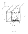
- the Fig. 1 shows a perspective view of a composite profile 100.
- the composite profile 100 has a first outer profile part 1 and a second outer profile part 2, which extend in a longitudinal direction z.
- the outer profile parts 1 and 2 are for example aluminum profiles.
- External profile part here refers to a profile part which is arranged on an outer side of the composite profile, such as. B. an inner shell or an outer shell.
- the outer profile parts may also be formed of another metal such as steel or the like.
- the two outer profile parts 1, 2 are connected by insulating ribs 4, 5, which extend in the longitudinal direction z, to form a gap 6 between the outer profile parts 1, 2.
- the outer profile parts 1, 2 and the insulating webs 4, 5 have different outer surfaces on which a powder coating is to be applied.
- a coating can be applied in a known manner at temperatures in a range between, for example, 150 ° C and 230 ° C.
- the coating temperature may be, for example, in a range between 175 ° C to 225 ° C, especially at 180 ° C, 185 ° C, 190 ° C, 195 ° C, 200 ° C, 205 ° C, 210 ° C, 215 ° C or 220 ° C.
- Each of these individual temperature values may represent either an upper or a lower limit of a corresponding temperature range for the coating.
- the insulating webs 4, 5 are formed here substantially the same, so that in the following only the insulating bar 4 will be described in more detail.
- the insulating bars may be formed differently.
- only one of the two insulating webs may have the electrically conductive longitudinal elements described below.
- the insulating bar 4 extends in the longitudinal direction z and consists of a thermally insulating plastic, for example PA66GF25.
- the insulating bar 4 has, in a cross section perpendicular to the longitudinal direction z, an insulating bar body 4a having a width B in a first transverse direction x.
- dovetail-shaped connecting portions 4b, 4c for connection to the outer profile parts 1, 2 are provided by rolling.
- a plurality of electrically conductive longitudinal elements 8 which in the in Fig. 1 embodiment shown are formed as wires, attached to the Isolierstegoasa 4a.
- the wires 8 extend spaced from each other in the longitudinal direction z.
- a cross section of the wires 8 or a dimension b thereof in the first transverse direction x is clearly smaller than a distance d2 between two adjacent wires, and considerably smaller than the width B of the insulating bar body 4a.
- the wires 8 of the External profile parts 1, 2 also spaced at a distance d1, which is significantly larger than the cross section b of the wires 8.
- the wires 8 are glued to the insulating bar body 4a using, for example, a suitable adhesive.
- the wires 8 are formed from a metal such as steel or aluminum, wherein it is preferred that the wires are made of the same material as the outer profile parts 1, 2, so that an electrochemical interaction between the wires 8 and the outer profile parts 1, 2 is prevented ,
- the wires 8 may further comprise, at least in sections, an electrically insulating sheath or coating.
- the wires 8 are connected to each other at one end of the composite profile 100 in the longitudinal direction z by an electrically conductive film 12 extending in the first transverse direction x.
- the electrically conductive film 12 may be self-adhesive, for example, so that it can be easily attached to the insulating bar 4 and the wires 8.
- the electrically conductive film 12 surrounds the connecting portions 4b, 4c of the connecting web 4, so that the electrically conductive film 12 is connected at a compound thereof by rolling with the likewise conductive outer profile parts 1, 2. In this way, an electrical connection between the outer profile parts 1, 2 and the wires 8 is obtained via the electrically conductive film 12.
- This in Fig. 1 shown composite profile 100 can be powder-coated by applying a suitable potential to the outer profile parts 1, 2 in a known manner. Since the wires 8, which extend over the entire length of the insulating strip 4 in the longitudinal direction z, are at the same potential as the outer profile parts 1, 2, an electric field is formed by the wires 8, which causes the powder particles move along the field lines towards the outside of the insulating strip 4 to be coated and stick there. It will be apparent to those skilled in the art that in this manner a relatively uniform electric field can be formed along the entire length of the insulating web 4 both in the longitudinal direction z and in the first transverse direction x, so that the outside of the insulating web 4 is evenly coated with the powder can.
- the number or the diameter b of the wires 8 and their distance d2 from each other depending on the geometry of the insulating bar 4 and / or the type of coating can be adjusted. Furthermore, it is understood that, depending on the distance of the outer profile parts 1, 2 in The first transverse direction x a larger or smaller number of wires 8 may be provided. At a relatively small distance may also be sufficient, a single wire 8.
- the electrically conductive film 12 may be provided only at one end of the composite profile 100 and the insulating bar 4, respectively, or may be provided at both ends of the composite profile 100 and the insulating bar 4 and / or at one or more positions between both ends. It is obvious that for contacting the wires 8 with the outer profile parts 1, 2 only at a position along the longitudinal direction z, an electrical connection must be present.
- the wires 8 may be attached to the insulating body 4a in other ways.
- the Fig. 2 shows a cross section perpendicular to the longitudinal direction z by a further embodiment of an insulating web 4 for a composite profile as in Fig. 1 Composite profile 100 shown.
- 4i receiving grooves 4d for the wires 8 are formed on the insulating web body 4a on the side 4i opposite its outer side.
- the receiving grooves 4d are formed for example from two opposite hook-shaped projections which have a certain elasticity, so that the wires 8 can engage in the receiving grooves 4d.
- the receiving grooves 4d and the wires 8 extend as in the Fig. 1 shown embodiment in the longitudinal direction z.
- the contacting between the wires 8 and the outer profile parts 1, 2 can be done in different ways.
- an electrically conductive film may be provided over the openings of the receiving grooves 4d, so that the film is fastened together with the wires 8 in the receiving grooves 4d.
- the wires 8 are exposed and as in Fig. 1 shown connected via an electrically conductive film.
- the wires 8 may be fixed in the longitudinal grooves 4d so as to protrude from the ends of the insulating bar 4, and the protruding ends of the wires 8 may be bundled or otherwise connected to each other, and then opened be suitably connected to one or both of the outer profile parts 1, 2, which will be described in more detail later.
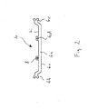
- the Fig. 3 shows a perspective view of another embodiment of an insulating web 4 for a composite profile as in Fig. 1 Composite profile 100 shown.
- the wires 8 are fastened to the outer side 4o of the insulating bar body 4a opposite side 4i of the insulating bar body 4a by using in each case a strip of an adhesive film 9.
- the wires 8 can as in the Fig. 2 embodiment shown by removing the adhesive films 9 and applying an electrically conductive film or connecting the same at one end of the insulating strip 4 in the longitudinal direction z to the outer profile parts 1, 2 of the composite profile 100 are connected.
- the Fig. 4 shows a perspective view of another embodiment of an insulating web 4 for a composite profile as in Fig. 1 shown composite profile 100.
- the electrically conductive longitudinal elements 8 are designed as strips which are provided on the side 4i thereof opposite the outer side 4o of the insulating body 4a.
- the strips 8 may be formed of a metal such as steel or aluminum, or of an electrically conductive film such as an aluminum film. In the case of metal strips, these can be glued with their broad side on the side surface of the Isoliersteg stresses 4a, for example using a suitable adhesive. Alternatively, the metal strips may be covered with an adhesive film and adhered to the insulating bar. In the case of an electrically conductive film such as an aluminum film, the electroconductive film may be self-adherent.
- the strips 8 can as in Fig. 1 shown using an electrically conductive film 12 with each other and with the outer profile parts 1, 2 are connected.
- the strips 8 may be provided so as to protrude beyond the ends of the insulating bar 4 in the longitudinal direction z and be connected to each other at the protruding ends with each other and with the outer profile parts 100, for example, using one or more electrically conductive wires or like.
- the strips 8 may be connected to one another and / or to one or both of the outer profile parts 1, 2 at one or more positions along the longitudinal direction z. Further, the strips 8 through the electrically conductive film 12, the at a plurality of positions along the longitudinal direction z is provided, be attached directly to the insulating web 4.
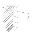
- the Fig. 5 shows a perspective view of another embodiment of an insulating web 4 for a composite profile.
- Fig. 5 is a modification of in Fig. 4 shown embodiment, in which electrically conductive strips 8 made of aluminum on ribs 4f, which are formed on the outside 4o opposite side 4i of the Isoliersteghaupt stresses 4a, are attached.
- the aluminum strips 8 are clamped to the ribs 4f. The contacting of the strips 8 with each other and with the outer profile parts 1, 2, to the previously with reference to Fig. 4 be made described manner.
- the Fig. 6 shows a cross section of a part of a Isolierstegs 4 for a composite profile as that in the Fig. 1 shown composite profile 100 according to another embodiment.
- the insulating web body 4a has three fastening sections 4r, 4t, which are provided on the side 4i opposite the outer side 4o.
- the exemplary embodiment shown in FIG Fig. 6 is shown, as provided by the side surface 4i of the Isoliersteg stresses 4a pin 4t and a arranged between the two pins complementary groove 4r as the mounting portions.
- a separate connecting part 7 is fixed, which is provided for connecting the insulating web 4 with, for example, a further insulating web, which is identical to the insulating web 4.
- the connecting part 7 can be connected via a latching connection with the insulating web 4 and the second, not shown insulating web.
- the connecting part 7 is formed, for example, from the same material as the insulating web 4 and has fastening portions that are complementary to the mounting portions 4r, 4t of the insulating web 4 are formed.
- a wire 8 is thereby fixed to the insulating bar 4 that it is clamped between the mounting portion 4r of the insulating bar 4 and the complementary mounting portion of the connecting part 7.
- a receiving groove 4d for the wire 8 is provided in a part of the fixing portion 4r. Even if in Fig. 6 only one wire 8 is shown, it is understood that provided at a plurality of connection points of the connecting part 7 with the Isoliersteg stresses 4a wires 8 could be.
- attachment portions may be provided on the Isoliersteg Congress 4a.
- gluing or otherwise securing the wires 8 to the insulating bar body 4a may be dispensed with. The contacting of the wires 8, for example, with reference to the Fig. 2 described ways.
- the Fig. 7 shows a cross section of a hollow chamber insulating web 4 for a composite profile as in Fig. 1 shown composite profile 100 according to another embodiment.
- the insulating bar 4 has a first insulating bar body 4a, which is connected via two cross-connections 4x to a second insulating bar body 4y, so that a hollow chamber 4h is formed in the insulating bar 4.
- a foam core 10 is introduced, which serves to increase thermal insulation and this substantially completely fills.
- wires 8 extending in the longitudinal direction z are provided between the foam core 10 and the inner walls of the hollow chamber 4h.
- the wires 8 may be inserted into the hollow chamber 4h attached to the foam core 10, such as by gluing them to the same.
- the wires 8 may first be inserted into the hollow chamber 4h, positioned in a desired manner, and then pushed against the inner wall of the hollow chamber 4h by insertion of the foam core 10 and thus fixed.
- the wires 8 may protrude in the longitudinal direction z from the ends of the insulating strip 4 and be connected to each other and to one or both of the outer profile parts 1, 2 in the manner previously described.
- the Fig. 8 shows a cross section of a Isolierstegs 4 for a composite profile as in Fig. 1 shown composite profile 100 according to another embodiment.
- the IsolierstegACS 4a a cover 4g, which is connected at one end fixed to the insulating bar 4 and integrally formed therewith and at the other end via a latching connection 11 to the insulating bar 4 can be fastened, so that in the Isolierstegoasa 4a a hollow chamber 4h can be formed.
- the wires 8 are fastened to inner walls of the hollow chamber 4h, for example using an adhesive, an adhesive film, a receiving groove (not shown), etc.
- the wires 8 can be fixed to the cover 4g or the base part of the insulating bar body 4a before the cover 4g is closed.
- the wires 8 are preferably arranged as close as possible to the outer side 4o of the cover 4g to be coated, so that the electric field generated by the wires 8 is generated as close as possible to the outer side 4o to be coated. Therefore, two of the three wires 8 shown are disposed on the outside opposite inside 4i of the cover 4g. However, the third wire 8 can not be fixed directly to the side 4i due to the hinge connection of the cover 4g, so that it is fastened closer to the insulating bar main body 4a.
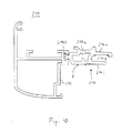
- Figs. 9A-9D show various possibilities for electrically connecting the longitudinal elements on the insulating web 4 with an outer profile part 1 of the composite profile 100, the in Fig. 1 is shown.
- the insulating web 4 is fixed in a known manner by rolling on the outer profile part 1, which has a Einrollhammer 1a and an abutment 1b.
- a sticking groove 4j is formed in a known manner.
- a metal bracket 14 is bent around the end 4s of the insulating bar 4 and fixed thereto.
- This metal clip comes when rolling the insulating bar 4 electrically conductive in contact with the outer profile part 1.
- the wires or strips 8 of the insulating strip 4 can be connected.
- the wires 8 projecting from one end of the insulating bar 4 may be linked or clamped individually between the clip 14 and the end 4s of the insulating bar 4, so that they are connected to the outdoor profile part 1 via the clip 14.
- electrically conductive strips 8 are provided instead of the wires, they can be used, for example be connected by a wire or a conductive film, which can then be clamped between the bracket 14 and the end 4s of the insulating 4.
- an additional groove 4k is provided in the end of the connecting portion 4b of the insulating bar 4, which is formed opposite the Einrollhammers 1a of the outer profile part 1.
- this groove 4k for example, the wires 8 can be inserted individually or already connected to each other, so that when rolling the Isolierstegs 4, the wires 8 can also be safely brought into contact with the outer profile part 1 in contact.
- the adhesive groove 4j provided at the end 4s of the insulating bar 4 is connected to the gap 6 via a passage 41 provided in the connecting portion 4b (see FIG. Fig. 1 ), in which the wires 8 are arranged.
- the wires in a region of the insulating bar 4 which is not immediately adjacent to the end thereof in the longitudinal direction z can be passed through the channel 41 and brought into contact with the outer profile part 1 in the adhesive groove 4j.
- the contact point is better protected, and it is ensured that the contact with the outer profile part 1 can be reliably made.
- the wires 8 at the end of the composite profile 100 (see FIG. Fig. 1 ) and are inserted into the adhesive groove 4j from outside, being curved or bent in the adhesive groove 4j, so that a portion of the wires is pressed against the outer profile member 1, as shown in FIG Fig. 9D is shown schematically.
- wires or strips 8 have been described as separate components which are secured to the insulating bar 4 using suitable fasteners such as adhesive sheets, receiving grooves, etc., it will be understood that in other embodiments the wires or strips 8 are part a single component which is suitably fixed to the insulating bar 4 and is electrically connected to the outer profile part 1.
- strips 8 suitable for use on an electrically non-conductive film could be made of an electrically conductive coating which is arranged at at least one position along the longitudinal direction z, for example at one end of the insulating strip 4. electrically connected to each other, or it could be a grid of the electrically conductive longitudinal elements and a plurality of electrically conductive cross members are used.
- the wires or strips 8 may be electrically isolated in sections, so that only at certain positions in the longitudinal direction z, an electrical connection thereof with each other and / or with the outer profile parts 1, 2 is possible. Further, the wires 8 may be provided in the form of a cable provided with an insulation, which can be stripped at appropriate locations to allow electrical connection with one or both of the outer profile parts.
- only one longitudinal element 8 in the form of a wire or strip is provided, which is then preferably fastened centrally to the Isoliersteg Congress 4a.
- the single wire or strip 8 may be connected to one or both of the outer profile parts 1, 2 in the ways previously described.
- the longitudinal element 8 may for example have a width b in the transverse direction x, which is about 1 to 20 percent of the width B of the Isoliersteg stressess 4a.
- the width b of the elongate member may be 5, 10, or 15 percent of the width B of the insulator body, where each of these individual values may represent an upper or lower limit of a range of width. It should be noted that the values listed here for the width b of the longitudinal element 8 are also applicable to the embodiments in which a plurality of longitudinal elements 8 is provided.
- two outer profile parts were connected to each other via at least one Isoliersteg.
- a composite profile with only one outer profile part, which is connected to an insulating bar be powder-coated.
- Such a composite profile can be used for example in block windows.
- the Fig. 10 shows a cross section of a composite profile 200 according to an embodiment with only one outer profile part.
- the composite profile 200 has an outer profile part 201, which extends in the longitudinal direction z, and an insulating web 204 connected to the outer profile part 201.
- the insulating bar 204 has an insulating body 204a and a connecting portion 204b.
- the insulating bar 204 is connected to the outer profile part 201 via the connecting portion 204b, so that the insulating bar body 204a extends from the outer profile part 201.
- the Isoliersteg Sciences 204a may have any geometry in cross-section perpendicular to the longitudinal direction z.
- the insulating web body for example, a groove 204g for a glass strip and a plurality of projections.
- the IsolierstegSystem has on one side an outer surface 204o, which is visible in the installed state of the composite profile 200 from the outside.
- a plurality of electrically conductive longitudinal elements 8 are provided on one side 204i of the insulating web body 204o opposite the side 204o.
- the longitudinal elements 8 are provided, for example, on the opposite outer side of the insulating web 204 and in the interior of the groove 204g.
- the longitudinal members may also be mounted at other suitable positions on the insulating bar 204, for example only on the opposite outside of the insulating bar, but preferably near the outside 204o and not visible when installed. Even if in Fig. 10 a plurality of longitudinal elements are shown, in other embodiments, only one longitudinal element 8 may be provided.
- the longitudinal elements 8, as previously described with reference to the Fig. 1 to 8 formed longitudinal elements and fastened in a similar manner to the insulating web 204. Furthermore, the longitudinal elements 8 are electrically connected to each other and to the outer profile part 201 as described above. For example, the connection with the outer profile part 201 as in the Fig. 9 Shown by the ends of the in Fig. 10 shown wires 8 are connected to the outer profile part 201.
Landscapes
- Engineering & Computer Science (AREA)
- Civil Engineering (AREA)
- Structural Engineering (AREA)
- Laminated Bodies (AREA)
- Wing Frames And Configurations (AREA)
Applications Claiming Priority (1)
| Application Number | Priority Date | Filing Date | Title |
|---|---|---|---|
| DE102011110899A DE102011110899A1 (de) | 2011-08-17 | 2011-08-17 | Lackierfähiger Isoliersteg für ein Verbundprofil für Fenster-, Türen- oder Fassadenelemente |
Publications (2)
| Publication Number | Publication Date |
|---|---|
| EP2559838A2 true EP2559838A2 (fr) | 2013-02-20 |
| EP2559838A3 EP2559838A3 (fr) | 2014-07-23 |
Family
ID=46614375
Family Applications (1)
| Application Number | Title | Priority Date | Filing Date |
|---|---|---|---|
| EP12179227.9A Withdrawn EP2559838A3 (fr) | 2011-08-17 | 2012-08-03 | Paintable insulating bar for a compound profile for window, door or façade elements and insulating bar with same |
Country Status (2)
| Country | Link |
|---|---|
| EP (1) | EP2559838A3 (fr) |
| DE (1) | DE102011110899A1 (fr) |
Cited By (9)
| Publication number | Priority date | Publication date | Assignee | Title |
|---|---|---|---|---|
| WO2015140217A1 (fr) * | 2014-03-19 | 2015-09-24 | Ensinger Gmbh | Procédé servant à fabriquer une entretoise d'isolation |
| EP2864567B1 (fr) | 2012-06-20 | 2016-07-27 | Technoform Bautec Holding GmbH | Moulure isolante pour un profilé composite destinée à des fenêtres, des portes ou des éléments de façade et procédé de fabrication d'une telle moulure isolante et d'un profilé composite comprenant une telle moulure isolante |
| CN106813092A (zh) * | 2015-11-29 | 2017-06-09 | 北京谦硕科技有限公司 | 智能仓储机装饰专用铝框架异型材 |
| WO2018220078A1 (fr) | 2017-05-31 | 2018-12-06 | Technoform Bautec Holding Gmbh | Profilé pour éléments de fenêtre, de porte, de façade et de parement |
| WO2018220074A1 (fr) | 2017-05-31 | 2018-12-06 | Technoform Bautec Holding Gmbh | Profilé pour éléments de fenêtre, de porte, de façade et de parement |
| US20190119973A1 (en) * | 2016-04-26 | 2019-04-25 | Technoform Bautec Holding Gmbh | Insulating strip for door, window or façade elements, composite profile for door, window or façade elements, and method for finishing manufacturing of a roll-in head of an insulating strip for door, window or façade elements |
| EP3477035A1 (fr) | 2017-10-30 | 2019-05-01 | Technoform Glass Insulation Holding GmbH | Espaceur pour des applications photovoltaïques |
| US11898056B2 (en) | 2017-12-08 | 2024-02-13 | Ensinger Gmbh | Polymer-based substrate and method for producing the same |
| US12186775B2 (en) | 2017-12-08 | 2025-01-07 | Ensinger Gmbh | Polymer-based substrate and method for producing the same |
Families Citing this family (1)
| Publication number | Priority date | Publication date | Assignee | Title |
|---|---|---|---|---|
| AT14254U1 (de) * | 2014-08-26 | 2015-07-15 | Ifn Holding Ag | Fensterprofil |
Citations (6)
| Publication number | Priority date | Publication date | Assignee | Title |
|---|---|---|---|---|
| DE3939968A1 (de) | 1989-12-02 | 1991-06-06 | Schueco Int Gmbh & Co | Verbundprofil, insbesondere fuer fenster, tueren und fassaden |
| DE4409315A1 (de) | 1994-03-18 | 1995-09-21 | Caprano & Brunnhofer | Abstandshaltender Isolierprofilstab aus thermoplastischem Kunststoff an zweischaligen wärmedämmenden Bauelementen |
| DE19535975C1 (de) | 1995-09-27 | 1997-04-03 | Gartner & Co J | Elektrisch leitend verbundene wärmegedämmte Profile |
| EP0638368B1 (fr) | 1993-07-14 | 1997-08-27 | Wilfried Ensinger | Procédé pour revêtir des profilés composites avec des laques en poudres |
| EP1223188B1 (fr) | 2001-01-08 | 2005-02-23 | Technoform Caprano und Brunnhofer GmbH & Co. KG | Procédé pour préparer un profilé en matière plastique au revêtement par poudre |
| DE102010016926A1 (de) | 2009-05-16 | 2010-12-30 | Eichler Gmbh & Co.Kg | Verfahren und Beschichtungsanlage zur elektrostatischen Lackierung (Pulverbeschichtung) von elektrisch nicht leitenden Teilen |
Family Cites Families (2)
| Publication number | Priority date | Publication date | Assignee | Title |
|---|---|---|---|---|
| DE19900793C2 (de) * | 1999-01-12 | 2001-11-22 | Ingbuero Dr Ing Harald Schulz | Brandschutzleiste |
| EP1712718A1 (fr) * | 2005-04-13 | 2006-10-18 | Forster Rohr- & Profiltechnik AG | Profilé composite et méthode de fabrication de profilé composite pour cadres d'éléments de paroi, portes et fenêtres |
-
2011
- 2011-08-17 DE DE102011110899A patent/DE102011110899A1/de not_active Ceased
-
2012
- 2012-08-03 EP EP12179227.9A patent/EP2559838A3/fr not_active Withdrawn
Patent Citations (6)
| Publication number | Priority date | Publication date | Assignee | Title |
|---|---|---|---|---|
| DE3939968A1 (de) | 1989-12-02 | 1991-06-06 | Schueco Int Gmbh & Co | Verbundprofil, insbesondere fuer fenster, tueren und fassaden |
| EP0638368B1 (fr) | 1993-07-14 | 1997-08-27 | Wilfried Ensinger | Procédé pour revêtir des profilés composites avec des laques en poudres |
| DE4409315A1 (de) | 1994-03-18 | 1995-09-21 | Caprano & Brunnhofer | Abstandshaltender Isolierprofilstab aus thermoplastischem Kunststoff an zweischaligen wärmedämmenden Bauelementen |
| DE19535975C1 (de) | 1995-09-27 | 1997-04-03 | Gartner & Co J | Elektrisch leitend verbundene wärmegedämmte Profile |
| EP1223188B1 (fr) | 2001-01-08 | 2005-02-23 | Technoform Caprano und Brunnhofer GmbH & Co. KG | Procédé pour préparer un profilé en matière plastique au revêtement par poudre |
| DE102010016926A1 (de) | 2009-05-16 | 2010-12-30 | Eichler Gmbh & Co.Kg | Verfahren und Beschichtungsanlage zur elektrostatischen Lackierung (Pulverbeschichtung) von elektrisch nicht leitenden Teilen |
Cited By (16)
| Publication number | Priority date | Publication date | Assignee | Title |
|---|---|---|---|---|
| EP2864567B2 (fr) † | 2012-06-20 | 2019-10-09 | Technoform Bautec Holding GmbH | Moulure isolante pour un profilé composite destinée à des fenêtres, des portes ou des éléments de façade et procédé de fabrication d'une telle moulure isolante et d'un profilé composite comprenant une telle moulure isolante |
| EP2864567B1 (fr) | 2012-06-20 | 2016-07-27 | Technoform Bautec Holding GmbH | Moulure isolante pour un profilé composite destinée à des fenêtres, des portes ou des éléments de façade et procédé de fabrication d'une telle moulure isolante et d'un profilé composite comprenant une telle moulure isolante |
| WO2015140217A1 (fr) * | 2014-03-19 | 2015-09-24 | Ensinger Gmbh | Procédé servant à fabriquer une entretoise d'isolation |
| US10207443B2 (en) | 2014-03-19 | 2019-02-19 | Ensinger Gmbh | Method for manufacturing an insulating bar |
| CN106813092A (zh) * | 2015-11-29 | 2017-06-09 | 北京谦硕科技有限公司 | 智能仓储机装饰专用铝框架异型材 |
| US10858877B2 (en) * | 2016-04-26 | 2020-12-08 | Technoform Bautec Holding Gmbh | Insulating strip for door, window or façade elements, composite profile for door, window or façade elements, and method for finishing manufacturing of a roll-in head of an insulating strip for door, window or façade elements |
| US20190119973A1 (en) * | 2016-04-26 | 2019-04-25 | Technoform Bautec Holding Gmbh | Insulating strip for door, window or façade elements, composite profile for door, window or façade elements, and method for finishing manufacturing of a roll-in head of an insulating strip for door, window or façade elements |
| US11142942B2 (en) | 2017-05-31 | 2021-10-12 | Technoform Bautec Holding Gmbh | Profile for window, door, facade and cladding elements |
| WO2018220074A1 (fr) | 2017-05-31 | 2018-12-06 | Technoform Bautec Holding Gmbh | Profilé pour éléments de fenêtre, de porte, de façade et de parement |
| US11078715B2 (en) | 2017-05-31 | 2021-08-03 | Technoform Bautec Holding Gmbh | Profile for window, door, facade and cladding elements |
| WO2018220078A1 (fr) | 2017-05-31 | 2018-12-06 | Technoform Bautec Holding Gmbh | Profilé pour éléments de fenêtre, de porte, de façade et de parement |
| WO2019086384A1 (fr) | 2017-10-30 | 2019-05-09 | Technoform Glass Insulation Holding Gmbh | Espaceur pour applications photovoltaïques |
| EP3477035A1 (fr) | 2017-10-30 | 2019-05-01 | Technoform Glass Insulation Holding GmbH | Espaceur pour des applications photovoltaïques |
| US11466508B2 (en) | 2017-10-30 | 2022-10-11 | Technoform Glass Insulation Holding Gmbh | Spacer for photovoltaic applications |
| US11898056B2 (en) | 2017-12-08 | 2024-02-13 | Ensinger Gmbh | Polymer-based substrate and method for producing the same |
| US12186775B2 (en) | 2017-12-08 | 2025-01-07 | Ensinger Gmbh | Polymer-based substrate and method for producing the same |
Also Published As
| Publication number | Publication date |
|---|---|
| DE102011110899A1 (de) | 2013-02-21 |
| EP2559838A3 (fr) | 2014-07-23 |
Similar Documents
| Publication | Publication Date | Title |
|---|---|---|
| EP2559838A2 (fr) | Paintable insulating bar for a compound profile for window, door or façade elements and insulating bar with same | |
| EP2044284B2 (fr) | Entretoise isolante sous forme d'échelle pour profilé composite pour éléments de fenêtres, de portes et de façades et profilé composite pour éléments de fenêtres, de portes et de façades | |
| DE2658708C3 (de) | Kabelkanal | |
| EP1467599A2 (fr) | Dispositif pour l'admission des éléments de chauffe en céramique et procédé pour la production de tels | |
| EP2527580B1 (fr) | Insert d'isolation pour un cadre formé de profilés | |
| DE102016103439B4 (de) | Kontaktstelle eines Flachleiters | |
| EP3701598B1 (fr) | Support de ligne, élément de barre conductrice, système de barre conductrice, élément de connexion mécanique pour un système de barre conductrice, procédé de fabrication d'un élément de barre conductrice et procédé de fabrication d'un système de barre conductrice | |
| EP2864567B2 (fr) | Moulure isolante pour un profilé composite destinée à des fenêtres, des portes ou des éléments de façade et procédé de fabrication d'une telle moulure isolante et d'un profilé composite comprenant une telle moulure isolante | |
| DE10119653C1 (de) | Mehrleiteranordnung zur Energie- und/oder Datenübertragung | |
| EP3743582A1 (fr) | Vitrage isolant, fenêtre et procédé pour sa fabrication | |
| DE10333451A1 (de) | Vorrichtung zur Aufnahme von Keramik-Heizelementen und Verfahren zur Herstellung einer solchen | |
| EP3555404B1 (fr) | Profilé composite à isolation thermique en plastique et métal | |
| EP0475417A2 (fr) | Agencement d'éléments de conduite de câbles électriques dans les façades de bâtiments | |
| DE69423054T3 (de) | Glasscheibe mit Anschlusselement | |
| EP1002924A2 (fr) | Profilé composite calorifuge, en particulier pour fenêtres, portes, façades ou similaires | |
| EP0906999B2 (fr) | Ame isolante de profilés composites de cadres de fenêtre ou de porte | |
| DE102008020988A1 (de) | Wärmeisolierendes Rahmenprofil für die Herstellung von Tür- und Fensterrahmen | |
| DE102009008909A1 (de) | Flachprofil mit Befestigungsnuten | |
| DE1779695A1 (de) | Bauelement in Form einer Heiztafel | |
| DE202007009106U1 (de) | Leiterförmiger Isoliersteg für ein Verbundprofil für Fenster-, Türen- und Fassadenelemente und Verbundprofil für Fenster-, Türen und Fassadenelemente | |
| DE102012206330A1 (de) | Verdrillte Leitungen durch Drucktechnologie | |
| CH701498A1 (de) | Gedichtete Strombrücke. | |
| DE7406973U (de) | Flachkabel | |
| DE10308663A1 (de) | Flachbandleitung mit Metall beschichten | |
| DE19855703B4 (de) | Anordnung zur Montage eines Erdungsbleches zur Erdung von einzelnen Bauteilen |
Legal Events
| Date | Code | Title | Description |
|---|---|---|---|
| PUAI | Public reference made under article 153(3) epc to a published international application that has entered the european phase |
Free format text: ORIGINAL CODE: 0009012 |
|
| AK | Designated contracting states |
Kind code of ref document: A2 Designated state(s): AL AT BE BG CH CY CZ DE DK EE ES FI FR GB GR HR HU IE IS IT LI LT LU LV MC MK MT NL NO PL PT RO RS SE SI SK SM TR |
|
| AX | Request for extension of the european patent |
Extension state: BA ME |
|
| PUAL | Search report despatched |
Free format text: ORIGINAL CODE: 0009013 |
|
| AK | Designated contracting states |
Kind code of ref document: A3 Designated state(s): AL AT BE BG CH CY CZ DE DK EE ES FI FR GB GR HR HU IE IS IT LI LT LU LV MC MK MT NL NO PL PT RO RS SE SI SK SM TR |
|
| AX | Request for extension of the european patent |
Extension state: BA ME |
|
| RIC1 | Information provided on ipc code assigned before grant |
Ipc: E06B 3/263 20060101AFI20140619BHEP |
|
| 17P | Request for examination filed |
Effective date: 20150122 |
|
| RBV | Designated contracting states (corrected) |
Designated state(s): AL AT BE BG CH CY CZ DE DK EE ES FI FR GB GR HR HU IE IS IT LI LT LU LV MC MK MT NL NO PL PT RO RS SE SI SK SM TR |
|
| 17Q | First examination report despatched |
Effective date: 20160504 |
|
| STAA | Information on the status of an ep patent application or granted ep patent |
Free format text: STATUS: THE APPLICATION IS DEEMED TO BE WITHDRAWN |
|
| 18D | Application deemed to be withdrawn |
Effective date: 20160915 |