EP2561285B1 - Diffuseur d'air et système de circulation d'air - Google Patents
Diffuseur d'air et système de circulation d'air Download PDFInfo
- Publication number
- EP2561285B1 EP2561285B1 EP11771390.9A EP11771390A EP2561285B1 EP 2561285 B1 EP2561285 B1 EP 2561285B1 EP 11771390 A EP11771390 A EP 11771390A EP 2561285 B1 EP2561285 B1 EP 2561285B1
- Authority
- EP
- European Patent Office
- Prior art keywords
- airstream
- primary
- airflow rate
- diffuser
- discharge
- Prior art date
- Legal status (The legal status is an assumption and is not a legal conclusion. Google has not performed a legal analysis and makes no representation as to the accuracy of the status listed.)
- Active
Links
Images


Classifications
-
- F—MECHANICAL ENGINEERING; LIGHTING; HEATING; WEAPONS; BLASTING
- F24—HEATING; RANGES; VENTILATING
- F24F—AIR-CONDITIONING; AIR-HUMIDIFICATION; VENTILATION; USE OF AIR CURRENTS FOR SCREENING
- F24F13/00—Details common to, or for air-conditioning, air-humidification, ventilation or use of air currents for screening
- F24F13/08—Air-flow control members, e.g. louvres, grilles, flaps or guide plates
- F24F13/10—Air-flow control members, e.g. louvres, grilles, flaps or guide plates movable, e.g. dampers
-
- F—MECHANICAL ENGINEERING; LIGHTING; HEATING; WEAPONS; BLASTING
- F24—HEATING; RANGES; VENTILATING
- F24F—AIR-CONDITIONING; AIR-HUMIDIFICATION; VENTILATION; USE OF AIR CURRENTS FOR SCREENING
- F24F13/00—Details common to, or for air-conditioning, air-humidification, ventilation or use of air currents for screening
- F24F13/02—Ducting arrangements
- F24F13/06—Outlets for directing or distributing air into rooms or spaces, e.g. ceiling air diffuser
- F24F13/065—Outlets for directing or distributing air into rooms or spaces, e.g. ceiling air diffuser formed as cylindrical or spherical bodies which are rotatable
-
- F—MECHANICAL ENGINEERING; LIGHTING; HEATING; WEAPONS; BLASTING
- F24—HEATING; RANGES; VENTILATING
- F24F—AIR-CONDITIONING; AIR-HUMIDIFICATION; VENTILATION; USE OF AIR CURRENTS FOR SCREENING
- F24F13/00—Details common to, or for air-conditioning, air-humidification, ventilation or use of air currents for screening
- F24F13/26—Arrangements for air-circulation by means of induction, e.g. by fluid coupling or thermal effect
-
- F—MECHANICAL ENGINEERING; LIGHTING; HEATING; WEAPONS; BLASTING
- F24—HEATING; RANGES; VENTILATING
- F24F—AIR-CONDITIONING; AIR-HUMIDIFICATION; VENTILATION; USE OF AIR CURRENTS FOR SCREENING
- F24F2221/00—Details or features not otherwise provided for
- F24F2221/14—Details or features not otherwise provided for mounted on the ceiling
Definitions
- the present invention relates to an air diffuser.
- Embodiments of the invention find particular, but not exclusive, use as a ceiling swirl diffuser, a floor swirl diffuser or a linear slot diffuser, as part of an installed air delivery system.
- adjustable dampers or adjustable blades for airflow adjustment that provide a generally constant discharge velocity from the diffuser to maintain largely constant throw of the supply air into the occupancy space regardless of the damper or blade airflow setting.
- adjustable dampers or blades may be regulated by means of thermally, electrically or pneumatically powered actuators, allowing a degree of individual occupancy space air temperature control to be achieved for the subzone served by that diffuser.
- Adjustable blades are sometimes used to alter diffuser discharge direction-manually or by means of thermal, pneumatic or electric actuators.
- the airflow rate from such diffusers and the position of the diffuser dampers or blades is often affected by supply air pressure fluctuations in the supply duct system, e.g. due to the opening or closing of other dampers. This often results in poor temperature control of the subzones in question as the airflow rate discharged by each diffuser increases or decreases due to the increased or decreased supply air pressure, respectively, and due to further opening or closing of the diffuser's adjustable damper or adjustable blades caused by the elasticity of the damper/blade mechanism.
- An air diffuser according to the preamble of claim 1 is known from JP 11-118233 .
- the present invention provides an air diffuser comprising, at least one primary discharge element and at least one secondary discharge element, wherein:
- the primary airstream when discharged in the absence of the secondary airstream may be substantially different to the discharge direction of the primary airstream when discharged in the presence of the secondary airstream.
- a secondary airflow rate element is manipulable to vary the airflow rate of the secondary airstream.
- the discharge direction of the primary airstream may vary when the secondary airflow rate element is manipulated.
- a primary airflow rate element may be manipulable to vary the airflow rate of the primary airstream.
- manipulation of the common airflow rate element reduces the airflow rate of the primary airstream without substantially varying the airflow rate of the secondary airstream.
- Manipulation of the common airflow rate element may reduce the airflow rate of the secondary airstream without substantially varying the airflow rate of the primary airstream.
- Manipulation of the common airflow rate element may reduce the airflow rate of the primary airstream without substantially varying the combined airflow rates of the primary airstream and of the secondary airstream.
- Manipulation of the common airflow rate element may reduce the airflow rate of the secondary airstream without substantially varying the combined airflow rates of the primary airstream and of the secondary airstream.
- the primary discharge element is manipulable to alter the airflow rate of the primary airstream.
- the primary discharge element may be manipulable to alter the airflow direction of the primary airstream.
- the airflow rate discharged by the primary discharge element may remain largely constant, for a constant total supply air pressure, in the range of airflow direction adjustment.
- the secondary discharge element is manipulable to alter the airflow rate of the secondary airstream.
- the secondary discharge element may be manipulable to alter the airflow direction of the secondary airstream.
- the primary and secondary discharge elements may share a common vane, the manipulation of which varies the discharge direction of at least one of the primary and secondary airstreams.
- Manipulation of the common vane may vary the discharge direction of the combined primary and secondary airstreams.
- the combined airflow rate discharged by the primary and secondary discharge elements may remain largely constant, for a constant total supply air pressure, in the range of airflow direction adjustment.
- the primary and secondary discharge elements may share a common vane, the manipulation of which varies the airflow rate of at least one of the primary and secondary airstreams.
- Manipulation of the common vane may vary the airflow rate of the combined primary and secondary airstreams.
- deflection of the primary discharge element vane due to an increase or decrease in supply air pressure causes the primary discharge element aperture to be reduced or increased, respectively.
- the primary and secondary discharge elements may share at least one common vane, deflection of which due to an increase or decrease in supply air pressure causes the apertures of the primary and the secondary discharge elements to be reduced or increased, respectively.
- the air diffuser in accordance with a first aspect may be incorporated in a ducting system.
- the air diffuser in accordance with a first aspect may be incorporated in an air supply system.
- Ceiling diffusers in buildings are usually designed to discharge air horizontally above head height, with a throw that largely covers the footprint of the space to be dealt with by each diffuser, as reduced throw (i.e. under-throw) increases the threat of dumping in cooling mode, thereby creating draughts and poor temperature distribution in the occupancy space. Conversely, increased throw (i.e. over-throw) increases the threat of air streams clashing with one another or with obstructions, such as walls, thereby increasing the threat of draughts.
- diffusers with a largely downward discharge direction are often selected so as to compensate for the buoyancy of the hot supply air, thereby improving the penetration of warm supply air into the low level occupancy zone.
- Ceiling swirl diffusers are increasingly being used in preference to four-way blow diffusers or other low induction air diffusion equipment for both of aforementioned applications, as their highly inductive discharge draws in and mixes large quantities of room air into the discharged supply air stream, thereby rapidly breaking down the supply-to-room temperature differential to provide more uniform temperature distribution throughout the occupancy space whilst simultaneously bringing about rapid discharge velocity decay, which enhances draught-free comfort.
- variable speed supply air fans or variable air volume (VAV) supply air systems are often used to supply conditioned air to the diffusers, especially in cooling mode.
- VAV variable air volume
- the diffusers need to provide stable horizontal discharge with relatively constant horizontal throws of the low temperature supply air, at both high and low airflow rates.
- high airflow rates generally increase throw, often producing over-throw, which may cause draughts where air streams from adjacent diffusers clash or where air streams hit obstructions such as walls or bulkheads;
- low airflow rates generally reduce throw, often causing zones of stagnation and of increased air temperature beyond the throw of the diffuser whilst cold spots or even draughts may occur close to or beneath the diffuser due to dumping of cold, dense supply air into the occupancy space.
- Standard horizontal discharge ceiling swirl diffusers with fixed horizontal discharge perform substantially better, both in terms of efficiency and perceived comfort, than horizontal discharge four-way blow diffusers, due to the higher induction ratios and better mixing of supply and room air provided by the former, but even so, a turndown ratio to approximately 30 to 40 percent is usually the lower limit of the former in cooling mode, especially if the supply-to-room temperature differential is high (often as high as 16 K); and heating effectiveness of the former is only slightly improved due to the increased mixing, but it is nevertheless poor due to the horizontal discharge direction of such standard horizontal discharge swirl diffusers.
- Adjustable dampers arranged to maintain a largely constant supply air stream velocity onto a portion of the swirl vanes, are sometimes used directly upstream of the diffuser so as to decrease the minimum permissible diffuser airflow rate.
- dampers are often motorised for VAV applications, and hence extend the VAV range of the diffuser, however they typically blank off a portion of the swirl blades even at the maximum airflow setting, thereby necessitating the need for oversized diffusers, and they tend to generate noise due to the increased air stream velocity onto the active portion of the swirl blades.
- Swirl diffusers with adjustable discharge direction are often used to improve heating efficiency by directing the warm supply air downwards.
- Such diffusers often incorporate thermally powered or electric or pneumatic actuators that automatically adjust discharge direction as a function of the supply air temperature or the supply-to-room air temperature differential.
- Adjustable blade angle tends to offer the best heating penetration to a low level, but cooling performance is compromised due to the extremely flat blade angle required to discharge air horizontally, as this, in turn, restricts the aperture between diffuser blades.
- relatively flat blade angles are required for all of the swirl diffusers of the prior art in cooling mode; they, therefore, have to be selected with relatively large diffuser face sizes in relation to the airflow rate to be discharged, negatively impacting space requirements, costs and aesthetics.
- the embodiments, as described herein, relate generally to an air diffuser assembly for ceiling discharge with an air supply supplied from a pressure plenum or duct.
- Figure 1a is a diagram illustrating the bottom view, and Figure 1b the side section view of a typical ceiling swirl diffuser (18) of the prior art, in which a face flange (1) that abuts ceiling or duct penetration (2) may be included in the diffuser discharge face plane (1a), and in which supply airstream (3) flows into diffuser inlet (4) from duct or supply plenum (5).
- An optional diffuser damper shown fully open (6a) and fully closed (6b), may be used to manually adjust the airflow rate to the diffuser.
- the airflow rate of airstream (3) to the diffuser may, additionally, be automatically varied by means of a variable speed drive fan, motorised damper or similar located upstream of diffuser inlet (4).
- Such airflow rate adjustment of supply air stream (3) causes both the airflow rate and the velocity of damper airstream (7) onto swirl vanes (8) to increase or decrease simultaneously, bringing about strong changes to the throw of discharged swirl airstream (9) into the occupancy space, as throw is a function of airflow rate multiplied by discharge velocity.
- Such changes in the throw of swirl airstream (9) compromise comfort, as over-throw increases the threat of draughts, and under-throw that of stagnation.
- the minimum airflow rate is typically limited to approximately 30% and 40% of the maximum airflow rate so as to prevent the cold and dense supply air from dumping into the occupancy space when supply airstream airflow rate (3), is turned down.
- diffusers of the prior art may adjust supply airstream airflow rate (3) via electrically, pneumatically or thermally powered actuator (10), to open (6a) and close (6b) a diffuser damper mechanism in the diffuser that varies the airflow rate, at a largely constant velocity, of damper airstream (7) onto largely radial swirl blades (8), thereby discharging swirl airstream (9) of varying volume flow rate at largely constant discharge velocity over a large portion of the turndown range.
- electrically, pneumatically or thermally powered actuator (10) to open (6a) and close (6b) a diffuser damper mechanism in the diffuser that varies the airflow rate, at a largely constant velocity, of damper airstream (7) onto largely radial swirl blades (8), thereby discharging swirl airstream (9) of varying volume flow rate at largely constant discharge velocity over a large portion of the turndown range.
- diffuser damper (6a and 6b) blanks off airflow to that portion of swirl blades (8) directly beneath the damper, thereby reducing the maximum permissible airflow rate of the diffuser. This is sometimes partially compensated for by perforating the diffuser damper (6a and 6b) to allow low momentum supply air (11) to flow through the otherwise largely inactive portion of swirl blades (8), to be induced by the higher momentum discharged swirl airstream (9).
- damper airflow rate (7) increase due to the increase in supply air pressure, but it also increases due to an increase in the diffuser damper aperture through which damper airstream (7) is discharged, caused by the elasticity and play of the diffuser damper and associated actuator (10) mechanism. Consequently, the diffuser damper (6a and 6b) is pushed further open by the increase in supply air pressure. Changes in air pressure in supply duct or plenum (5), therefore, may cause strong uncontrolled increases and decreases in discharged swirl airflow rate (9), thereby compromising thermostatic temperature control and thermal comfort in the occupancy space.
- a diffuser damper (6a and 6b) operated by an actuator (10) that is thermally powered may be especially susceptible to such uncontrolled pressure induced aperture adjustment due to a variety of factors, such as the extremely sensitive mechanism required to deal with the short and relatively weak operating stroke of the actuator, the actuator's high hysteresis, and the sluggishness that the actuator's high thermal inertia causes to the control response.
- FIG 2 is a diagram illustrating side section views of the swirl blades (8) of a typical ceiling swirl diffuser of the prior art, as shown in Figure 1a , in which Figure 2a shows the relatively flat blade angle ( ⁇ ) to the diffuser discharge face plane (1a) required to achieve largely parallel discharge of swirl airstream (9a) relative to the diffuser discharge face plane (1a), as is generally required of a ceiling swirl diffuser operating in cooling mode.
- Shallow blade angle ( ⁇ ) reduces the swirl slot aperture (12) between adjacent swirl blades (8), thereby restricting the airflow rate of discharged swirl airstream (9a).
- Figure 2b shows a further embodiment of a typical ceiling swirl diffuser of the prior art, in this instance with adjustable blades, in which swirl blades (8) may be swivelled, manually or by means of at least one thermally, pneumatically or electrically powered actuator (not shown), to a steep angle ( ⁇ ) relative to the diffuser discharge face plane (1a), in which ( ⁇ ) > ( ⁇ ), to alter the discharge direction of swirl airstream (9b) to be largely perpendicular to the diffuser discharge face plane (1a), as may be required of a ceiling swirl diffuser operating in heating mode, especially if the discharge height is high.
- swirl blades (8) may be swivelled, manually or by means of at least one thermally, pneumatically or electrically powered actuator (not shown), to a steep angle ( ⁇ ) relative to the diffuser discharge face plane (1a), in which ( ⁇ ) > ( ⁇ ), to alter the discharge direction of swirl airstream (9b) to be largely perpendicular to the diffuser discharge face plane (1a), as may be required of
- Steep blade angle ( ⁇ ) increases the swirl slot aperture (12a) between adjacent swirl blades (8), thereby, for a largely constant total supply air pressure, increasing the airflow rate of discharged airstream (9b) relative to that of (9a).
- Changes to the angle of diffuser swirl blades (8) may, therefore, cause strong uncontrolled increases or decreases in discharged swirl airflow rate (9b and 9a), thereby compromising thermostatic temperature control and thermal comfort in the occupancy space served by that diffuser; these uncontrolled changes in supply airflow rate changes cannot be fully offset by additionally equipping the diffuser with adjustable diffuser damper (6a and 6b in Figure 1 ) driven by thermally, electrically or pneumatically powered actuator (10 in Figure 1 ), for the reasons described in Figure 1 .
- the change in the airflow rate of the discharged swirl airstream (9a and 9b) may cause supply airstream static pressure to the diffuser, and hence to the entire supply air system including other diffusers in that system, to change, thereby compromising thermostatic temperature control and thermal comfort produced by the entire system, including in other thermal zones, especially if such zones are served by diffusers with airflow rate adjustment by means of diffuser dampers (6a and 6b) that are thermally powered.
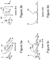
- Figure 3 is a diagram illustrating side section views of the swirl blades (8) of a ceiling swirl diffuser in accordance with an embodiment of the invention, in which Figure 3a shows the increased swirl airflow rate (9c) in comparison to that of the prior art (9a in Figure 2a ), achieved by increasing the aperture of swirl slot (12b) between swirl blades (8) as a result of the relatively steep blade angle ( ⁇ 1) to the diffuser discharge face plane (1a), whereby ( ⁇ 1) > ( ⁇ in Figure 2a ).
- Guide slot airstream (13) which may have a substantially smaller airflow rate than swirl airstream (9c), is discharged through guide slot (14) and attaches itself to guide vane (15) to be directed largely parallel to diffuser discharge face plane (1a) directly downstream of the diffuser.
- Discharged swirl airstream (9c) is redirected to a largely parallel direction relative to the diffuser discharge face plane (1a) by the induction of guide slot airstream (13), creating, relative to the diffuser discharge face plane (1a), a largely parallel movement away from the diffuser of the combined airstreams (9c and 13) directly downstream of the diffuser.
- Figure 3b shows a further embodiment of the invention in which swirl blades (8) may be swivelled, manually or by means of at least one thermally, pneumatically or electrically powered actuator (not shown), to a steep angle ( ⁇ ) relative to the plane of diffuser discharge face (1a), in which ( ⁇ ) > ( ⁇ 1), to largely close off guide slot (14), thereby shutting off slot airstream (13), and to alter the discharge direction of discharged swirl airstream (9d) to be largely perpendicular to the diffuser discharge face plane (1a).
- FIG 3c shows a further embodiment of the invention in which swirl blades (8) may be swivelled, manually or by means of at least one thermally, pneumatically or electrically powered actuator (not shown), to a shallow angle ( ⁇ 2) relative to the diffuser discharge face plane (1a), in which ( ⁇ 2) ⁇ ( ⁇ 1), to throttle both swirl airstream (9e) and guide slot airstream (13a) whilst maintaining largely constant discharge velocity of both airstreams and whilst maintaining a largely parallel movement away from the diffuser of the combined airstreams directly downstream of the diffuser relative to the diffuser discharge face plane (1a).
- Figure 3d shows swirl blades (8) swivelled to largely shut off airflow from the diffuser.
- Figure 4 is a diagram illustrating side section views of the swirl blades (8) of a ceiling swirl diffuser in accordance with an embodiment of the invention, in which Figure 4a shows the increased blade angle ( ⁇ '1) to the diffuser discharge face plane (1a), whereby ( ⁇ '1) > ( ⁇ in Figure 2a ).
- Diffuser damper (6c) is in the fully open position, maximising the apertures of guide slot (14) and swirl slot (12b1).
- Guide slot airstream (13) which may have a substantially smaller airflow rate than swirl airstream (9c1), is discharged through guide slot (14) and attaches itself to guide vane (15) to be directed largely parallel to diffuser discharge face plane (1a) directly downstream of the diffuser.
- Discharged swirl airstream (9c1) is redirected to a largely parallel direction relative to the diffuser discharge face plane (1a) by the induction of guide slot airstream (13), creating, relative to the diffuser discharge face plane (1a), a largely parallel movement away from the diffuser of the combined airstreams (9c1 and 13) directly downstream of the diffuser.
- Figure 4b shows a further embodiment of the invention in which diffuser damper (6d), has been slid, manually or by means of at least one thermally, pneumatically or electrically powered actuator (not shown), to largely close off guide slot (14), thereby largely shutting off guide slot airstream (13), so as to alter the discharge direction of discharged swirl airstream (9d1) to be largely directed away from the diffuser discharge face plane (1a).
- Figure 4c shows a further embodiment of the invention in which diffuser damper (6e) may be slid, manually or by means of at least one thermally, pneumatically or electrically powered actuator (not shown), to partially close the aperture of swirl slot (12d1), so as to throttle swirl airstream (9e1) whilst maintaining largely constant discharge velocity and whilst maintaining a largely parallel movement away from the diffuser of the combined swirl (9e1) and guide slot (13) airstreams directly downstream of the diffuser relative to the diffuser discharge face plane (1a).
- diffuser damper (6e) may be slid, manually or by means of at least one thermally, pneumatically or electrically powered actuator (not shown), to partially close the aperture of swirl slot (12d1), so as to throttle swirl airstream (9e1) whilst maintaining largely constant discharge velocity and whilst maintaining a largely parallel movement away from the diffuser of the combined swirl (9e1) and guide slot (13) airstreams directly downstream of the diffuser relative to the diffuser discharge face plane (1a).
- Figure 4d shows diffuser damper (6f) slid to largely shut off airflow from the diffuser whilst maintaining a largely parallel movement away from the diffuser of the guide slot airstream (13) directly downstream of the diffuser relative to the diffuser discharge face plane (1a).
- FIGs 5a and 5b are diagrams illustrating a top view and a section of a floor swirl diffuser in accordance with an embodiment of the invention, in which swirl slot (12e), which discharges swirl air stream (9f), alternates with guide slot (14a), which discharges guide slot air stream (13b). Swirl airstream (9f) is discharged at a relatively steep angle ( ⁇ 1) to the diffuser discharge face plane (1a).
- Guide slot airstream (13b) which may have a substantially smaller airflow rate than swirl airstream (9f), is discharged at a shallow angle (02) to the diffuser discharge face plane (1a), in which ( ⁇ 2) ⁇ ( ⁇ 1), so as to attach itself to the diffuser face (1b) to be directed largely parallel to diffuser discharge face plane (1a) directly downstream of the diffuser.
- Discharged swirl airstream (9f) is redirected to a largely parallel direction relative to the diffuser discharge face plane (1a) by the induction of discharged guide slot airstream (13b), creating, relative to the diffuser discharge face plane (1a), a largely parallel movement away from the diffuser of the combined airstreams (9f and 13b) directly downstream of the diffuser.
- the total floor swirl diffuser airflow rate discharged by this embodiment of the invention may be greater than that of a comparable floor swirl diffuser (i.e. of similar face size, slot length, slot width, number of slots and operating pressure) that produces discharge parallel to the diffuser discharge face plane but without alternating slot discharge angles.
- a comparable floor swirl diffuser i.e. of similar face size, slot length, slot width, number of slots and operating pressure
- Figure 6a is a diagram illustrating the bottom view of a linear slot diffuser, as it would appear in some embodiments both of the prior art and of the invention.
- a multitude of slotted barrels (16a or 16b) in the linear slot diffuser may have alternating discharge direction as shown in Figure 6b , which illustrates an embodiment of the prior art, and in Figure 6c , which illustrates an embodiment of the invention, in which the latter shows the increased airflow rate in comparison to that of the former by virtue of the increased discharge angle ( ⁇ 4 > ⁇ 3) of the primary air stream (9h relative to 9g) which results in reduced resistance, as well as due to the potential to increase the overall slot width (17b > 17a).
- Guide slot airstream (13c) which may have a substantially smaller airflow rate than primary airstream (9h), is discharged through guide slot (14b) and attaches itself to diffuser face flange (1c) to be directed largely parallel to diffuser discharge face plane (1a) directly downstream of the diffuser.
- Discharged primary airstream (9h) is redirected to a largely parallel direction relative to the diffuser discharge face plane (1a) by the induction of guide slot airstream (13c), creating, relative to the diffuser discharge face plane (1d), a largely parallel movement away from the diffuser of the combined airstreams (9h and 13c) directly downstream of the diffuser.
- Figure 6d shows embodiments of the prior art in which the left and right illustrations depict the diffuser discharge direction adjusted largely downwards, which may be achieved by turning the barrels (16a) to direct supply air largely downwards; the middle figure shows barrels (16a) turned to shut off supply airflow.
- Figure 6e shows a further embodiment of the invention in which the left and right illustrations depict barrels (16b) turned to direct supply air largely downwards; the middle figure shows barrels (16b) turned to shut off supply airflow.
- the embodiment illustrated in Figure 6e may have increased airflow rate in comparison to the downward discharge embodiment of the prior art illustrated in Figure 6d , by virtue of the reduced resistance to the airflow within the barrel (16b vs 16a), as well as due to the potential to increase the overall slot width (17c > 17a).
- the illustrations above show the discharge openings largely coincident with a plane that is largely coincident with the diffuser discharge plane. It will be appreciated by persons skilled in the art that the discharge openings need not be coincident with a plane (for example, they may lie on a curved surface) and that they need not be coincident with the diffuser discharge plane (which, for example, may be a perforated plate further downstream).
- An air delivery system incorporating the diffuser described herein provides the potential for substantial energy savings and more effective performance, as well as for improved thermal comfort, reduced capital cost and enhanced aesthetics.
- HVAC systems that deliver supply air to spaces via diffusers with guide slots in accordance with the invention may be designed to operate with variable speed drive fans or may incorporate devices, such as variable air volume (VAV) boxes, to reduce airflow during periods of low thermal load, thereby saving fan energy, as a diffuser as described by these embodiments of the invention, when configured to discharge air largely horizontally, can have the supply air turned down to a far lower airflow rate, whilst maintaining stable and largely horizontal discharge, than is possible with comparable diffusers of the prior art. Moreover, this is generally achieved without requiring an increase in operating pressure. This provides substantial potential for increased fan energy savings.
- VAV variable air volume
- the maximum airflow rate that may be discharged by a diffuser as described by some embodiments of the invention is greater than that of a comparable diffuser of the prior art, thereby potentially allowing a smaller number of diffusers to be used, or a smaller diffuser face size to be selected, hence reducing capital costs and improving aesthetics.
- Embodiments of the invention allow the diffuser to provide variable geometry airflow rate and discharge direction adjustment that improves occupancy zone air temperature control, increases heating efficiency, and reduces uncontrolled airflow rate fluctuations due to system supply air pressure changes, thereby improving both occupant comfort and system efficiency.
Landscapes
- Engineering & Computer Science (AREA)
- Chemical & Material Sciences (AREA)
- Combustion & Propulsion (AREA)
- Mechanical Engineering (AREA)
- General Engineering & Computer Science (AREA)
- Duct Arrangements (AREA)
- Air-Flow Control Members (AREA)
- Control Of Positive-Displacement Air Blowers (AREA)
Claims (16)
- Diffuseur d'air comprenant au moins un élément de décharge principal (12b, 12d, 12b1, 12d1) et au moins un élément de décharge secondaire (14), caractérisé en ce que l'élément de décharge secondaire (14) est prévu pour évacuer un flux d'air secondaire (13, 13a) capable de circuler sur au moins une surface qui oriente le flux d'air secondaire (13, 13a) sensiblement sur un plan de la face de décharge du diffuseur à proximité, directement vers le bas, de l'élément de décharge secondaire (14) ; et l'élément de décharge principal (12b, 12d, 12b1, 12d1) est prévu pour évacuer un flux d'air principal (9c, 9e, 9c1, 9e1) qui est induit par le flux d'air déchargé secondaire (13, 13a) de sorte que la direction du flux d'air déchargé principal (9c, 9e, 9c1, 9e1) soit largement déterminée par la direction de déplacement du flux d'air secondaire (13, 13a) ; caractérisé en ce que
l'élément de décharge principal définit un élément de débit d'air commun qui est manipulable afin de faire varier les débits d'air du flux d'air secondaire (13, 13a) et du flux d'air principal (9c, 9e, 9c1, 9e1) ; et dans lequel l'élément de débit d'air commun peut faire varier les débits d'air du flux d'air principal (9c, 9e, 9c1, 9e1) et du flux d'air secondaire (13, 13a) de manière sensiblement indépendante l'un de l'autre. - Diffuseur d'air selon la revendication 1, dans lequel le flux d'air principal présente un débit d'air sensiblement plus élevé que le flux d'air secondaire.
- Diffuseur d'air selon la revendication 1 ou 2, dans lequel la direction de décharge du flux d'air principal (9c, 9e, 9c1, 9e1), lorsqu'il est évacué en l'absence du flux d'air secondaire (13, 13a), est sensiblement différente de la direction de décharge du flux d'air principal (9c, 9e, 9c1, 9e1) lorsqu'il est évacué en présence du flux d'air secondaire (13,13a).
- Diffuseur d'air selon les revendications 1, 2 ou 3, dans lequel un élément de débit d'air secondaire est manipulable afin de faire varier le débit d'air du flux d'air secondaire (13, 13a).
- Diffuseur d'air selon la revendication 4, dans lequel la direction de décharge du flux d'air principal (9c, 9e, 9c1, 9e1) varie lorsque l'élément de débit d'air secondaire est manipulé.
- Diffuseur d'air selon l'une quelconque des revendications 1 à 5, dans lequel un élément de débit d'air principal est manipulable afin de faire varier le débit d'air du flux d'air principal (9c, 9e, 9c1, 9e1).
- Diffuseur d'air selon l'une quelconque des revendications 1 à 6, dans lequel la manipulation de l'élément de débit d'air commun réduit le débit d'air du flux d'air principal (9c, 9e, 9c1, 9e1) sans modifier sensiblement le débit d'air du flux d'air secondaire (13, 13a) ; ou
dans lequel la manipulation de l'élément de débit d'air commun réduit le débit d'air du flux d'air secondaire (13, 13a) sans modifier sensiblement le débit d'air du flux d'air principal (9c, 9e, 9c1, 9e1). - Diffuseur d'air selon l'une quelconque des revendications 1 à 6, dans lequel la manipulation de l'élément de débit d'air commun réduit le débit d'air du flux d'air principal (9c, 9e, 9c1, 9e1) sans modifier sensiblement les débits d'air combinés du flux d'air principal (9c, 9e, 9c1, 9e1) et du flux d'air secondaire (13, 13a) ; ou
dans lequel la manipulation de l'élément de débit d'air commun réduit le débit d'air du flux d'air secondaire (13, 13a) sans modifier sensiblement les débits d'air combinés du flux d'air principal (9c, 9e, 9c1, 9e1) et du flux d'air secondaire (13, 13a). - Diffuseur d'air selon l'une quelconque des revendications précédentes, dans lequel l'élément de décharge principal est manipulable afin de modifier le débit d'air du flux d'air principal (9c, 9e, 9c1, 9e1).
- Diffuseur d'air selon l'une quelconque des revendications précédentes, dans lequel l'élément de décharge principal est manipulable afin de modifier la direction du flux d'air principal (9c, 9e, 9c1, 9e1).
- Diffuseur d'air selon la revendication 10, dans lequel le débit d'air évacué par l'élément de décharge principal reste largement constant, pour une pression d'air d'alimentation totale constante, dans les limites d'ajustement de la direction du flux d'air.
- Diffuseur d'air selon l'une quelconque des revendications précédentes, dans lequel l'élément de décharge secondaire est manipulable afin de modifier le débit d'air du flux d'air secondaire (13, 13a).
- Diffuseur d'air selon l'une quelconque des revendications précédentes, dans lequel l'élément de décharge secondaire est manipulable afin de modifier la direction du flux d'air secondaire (13, 13a).
- Diffuseur d'air selon l'une quelconque des revendications précédentes, dans lequel la déviation de l'élément de décharge principal due à une augmentation ou une diminution de la pression d'air d'alimentation provoque une diminution ou une augmentation de l'ouverture de l'élément de décharge principal, respectivement.
- Système de conduites comprenant au moins un diffuseur d'air selon l'une quelconque des revendications 1 à 14.
- Système d'alimentation en air comprenant au moins un diffuseur d'air selon l'une quelconque des revendications 1 à 15.
Applications Claiming Priority (2)
| Application Number | Priority Date | Filing Date | Title |
|---|---|---|---|
| AU2010901724A AU2010901724A0 (en) | 2010-04-23 | An air diffuser and an air circulation system | |
| PCT/AU2011/000436 WO2011130778A1 (fr) | 2010-04-23 | 2011-04-27 | Diffuseur d'air et système de circulation d'air |
Publications (3)
| Publication Number | Publication Date |
|---|---|
| EP2561285A1 EP2561285A1 (fr) | 2013-02-27 |
| EP2561285A4 EP2561285A4 (fr) | 2014-04-09 |
| EP2561285B1 true EP2561285B1 (fr) | 2017-06-28 |
Family
ID=44833545
Family Applications (1)
| Application Number | Title | Priority Date | Filing Date |
|---|---|---|---|
| EP11771390.9A Active EP2561285B1 (fr) | 2010-04-23 | 2011-04-27 | Diffuseur d'air et système de circulation d'air |
Country Status (8)
| Country | Link |
|---|---|
| US (1) | US10337760B2 (fr) |
| EP (1) | EP2561285B1 (fr) |
| JP (1) | JP2013525726A (fr) |
| CN (1) | CN102933913B (fr) |
| AU (1) | AU2011242393B2 (fr) |
| CA (1) | CA2797196C (fr) |
| NZ (1) | NZ603730A (fr) |
| WO (1) | WO2011130778A1 (fr) |
Families Citing this family (14)
| Publication number | Priority date | Publication date | Assignee | Title |
|---|---|---|---|---|
| AU2016203447B2 (en) * | 2009-12-08 | 2018-02-22 | Fusion Hvac Pty Limited | A system and method for delivering air |
| DE102012019710A1 (de) * | 2012-10-08 | 2014-04-10 | Gea Air Treatment Gmbh | Decken- oder Wandgerät zum Einbringen gekühlter oder erwärmter Luft in einen Raum |
| EP2960591A1 (fr) * | 2014-06-27 | 2015-12-30 | Koolair, S.A. | Diffuseur d'air avec réglage automatique de la température |
| NZ631243A (en) * | 2014-09-08 | 2015-11-27 | Fusion Hvac Pty Ltd | Diffuser module |
| HUE056340T2 (hu) * | 2015-09-29 | 2022-02-28 | Kaip Pty Ltd | Levegõ befúvó |
| FI127646B (en) * | 2015-12-09 | 2018-11-15 | Sandbox Oy | Supply Unit |
| CN106274378B (zh) * | 2016-08-18 | 2018-04-13 | 博耐尔汽车电气系统有限公司 | 汽车空调hvac吹风模式的转换方法 |
| CN106314084B (zh) * | 2016-08-18 | 2018-04-13 | 博耐尔汽车电气系统有限公司 | 一种汽车空调hvac导风板 |
| CN108731108B (zh) * | 2018-06-28 | 2020-08-04 | 芜湖美智空调设备有限公司 | 空调器 |
| CN109458645A (zh) * | 2018-12-19 | 2019-03-12 | 西安建筑科技大学 | 一种架空地板对流辐射供暖末端 |
| US11187431B2 (en) | 2019-04-22 | 2021-11-30 | Air Distribution Technologies Ip, Llc | Variable flow adapters for air diffusers with damper |
| US11752838B2 (en) | 2019-04-22 | 2023-09-12 | Air Distribution Technologies Ip, Llc | Variable flow adapters for air diffusers of HVAC systems |
| CN110933904B (zh) * | 2019-11-08 | 2021-05-25 | 武汉琦隆科技发展有限公司 | 一种油烟净化器的高压电源箱 |
| EP4217665A4 (fr) | 2020-08-20 | 2024-10-30 | Kaip Pty Limited | Unité de diffusion et procédé de diffusion d'un flux d'air |
Family Cites Families (31)
| Publication number | Priority date | Publication date | Assignee | Title |
|---|---|---|---|---|
| GB495312A (en) | 1937-04-10 | 1938-11-10 | Norman Finlay Johnston | Improvements in and relating to ventilators, air diffusers and the like |
| US2715867A (en) * | 1950-05-03 | 1955-08-23 | Barber Colman Co | Air distribution unit |
| DE2451557C2 (de) * | 1974-10-30 | 1984-09-06 | Arnold Dipl.-Ing. 8904 Friedberg Scheel | Vorrichtung zum Belüften einer Aufenthaltszone in einem Raum |
| ZA771500B (en) * | 1977-03-11 | 1978-06-28 | Ventline Mfg Ltd | Improvements in or relating to air conditioning |
| JPS5460663A (en) | 1977-10-24 | 1979-05-16 | Matsushita Electric Ind Co Ltd | Fluid stream direction controller |
| GB8710157D0 (en) * | 1987-04-29 | 1987-06-03 | British Aerospace | Fluid flow control nozzles |
| JPH0490846U (fr) * | 1990-12-12 | 1992-08-07 | ||
| JPH05203254A (ja) * | 1992-01-23 | 1993-08-10 | Matsushita Refrig Co Ltd | 空気調和機の風向可変装置 |
| JPH06307711A (ja) | 1993-04-21 | 1994-11-01 | Matsushita Refrig Co Ltd | 空気調和装置 |
| JP3240854B2 (ja) | 1994-09-26 | 2001-12-25 | 三菱電機株式会社 | 空気調和機の吹出口 |
| US5722484A (en) * | 1995-12-26 | 1998-03-03 | Carrier Corporation | Louver assembly for fan discharge duct |
| JP3356257B2 (ja) * | 1996-06-06 | 2002-12-16 | 株式会社富士通ゼネラル | 空気調和機 |
| US6083101A (en) * | 1998-02-24 | 2000-07-04 | Mitsubishi Denki Kabushiki Kaisha | Device for controlling diffused air |
| JPH10141751A (ja) * | 1996-11-12 | 1998-05-29 | Shinko Kogyo Co Ltd | 空調用の誘引式吹出装置 |
| WO1998033022A1 (fr) * | 1997-01-28 | 1998-07-30 | Hart & Cooley, Inc. | Diffuseur d'air pourvu d'un mecanisme a rochet |
| JP3116874B2 (ja) * | 1997-10-14 | 2000-12-11 | ダイキン工業株式会社 | 空気調和装置の空気吹出口構造 |
| JP3677388B2 (ja) * | 1998-04-15 | 2005-07-27 | 松下エコシステムズ株式会社 | 浴室暖房換気乾燥ユニット用給排気グリル |
| JP4099740B2 (ja) | 1999-05-12 | 2008-06-11 | 東洋ゴム工業株式会社 | 室温調整機能をもつ空気膨脹型簡易ハウス |
| JP4533480B2 (ja) * | 1999-11-01 | 2010-09-01 | 空研工業株式会社 | 吹出口装置 |
| US6582293B1 (en) * | 1999-11-01 | 2003-06-24 | Andrew Siniarski | Air vent damper apparatus |
| FI113798B (fi) * | 2000-11-24 | 2004-06-15 | Halton Oy | Tuloilmalaite |
| FR2833339B1 (fr) * | 2001-12-10 | 2004-03-05 | Bense Dominique | Dispositif de traitement d'air |
| JP3900950B2 (ja) * | 2002-02-04 | 2007-04-04 | 三菱電機株式会社 | 天井カセット型空気調和機の化粧パネル |
| EP1344668B1 (fr) * | 2002-03-15 | 2006-11-08 | TRW Automotive Electronics & Components GmbH & Co. KG | Buse d'aération pour systèmes de ventilation |
| JP4311212B2 (ja) * | 2004-01-26 | 2009-08-12 | ダイキン工業株式会社 | 天井埋込型空気調和装置及びその制御方法 |
| JP2008232470A (ja) * | 2007-03-16 | 2008-10-02 | Mitsubishi Electric Corp | 空調室内機 |
| FI20075226A7 (fi) | 2007-04-03 | 2008-10-04 | Valtion Teknillinen Tutkimuskeskus | Tuloilmalaite ja menetelmä ilman puhdistamiseksi tuloilmalaitteessa |
| WO2009016838A1 (fr) * | 2007-07-31 | 2009-02-05 | Daikin Industries, Ltd. | Climatiseur et buse d'extension d'aspirateur |
| JP2010071499A (ja) * | 2008-09-17 | 2010-04-02 | Hitachi Appliances Inc | 空気調和機 |
| JP4803296B2 (ja) * | 2009-10-30 | 2011-10-26 | ダイキン工業株式会社 | 室内機及びそれを備えた空気調和機 |
| JP5267690B2 (ja) * | 2012-02-03 | 2013-08-21 | ダイキン工業株式会社 | 室内機 |
-
2011
- 2011-04-27 CN CN201180028530.1A patent/CN102933913B/zh active Active
- 2011-04-27 US US13/643,034 patent/US10337760B2/en active Active
- 2011-04-27 CA CA2797196A patent/CA2797196C/fr active Active
- 2011-04-27 NZ NZ603730A patent/NZ603730A/en unknown
- 2011-04-27 WO PCT/AU2011/000436 patent/WO2011130778A1/fr not_active Ceased
- 2011-04-27 EP EP11771390.9A patent/EP2561285B1/fr active Active
- 2011-04-27 AU AU2011242393A patent/AU2011242393B2/en active Active
- 2011-04-27 JP JP2013505276A patent/JP2013525726A/ja not_active Ceased
Also Published As
| Publication number | Publication date |
|---|---|
| EP2561285A1 (fr) | 2013-02-27 |
| US10337760B2 (en) | 2019-07-02 |
| AU2011242393B2 (en) | 2015-12-10 |
| EP2561285A4 (fr) | 2014-04-09 |
| CN102933913A (zh) | 2013-02-13 |
| US20130137359A1 (en) | 2013-05-30 |
| CN102933913B (zh) | 2015-09-30 |
| CA2797196A1 (fr) | 2011-10-27 |
| JP2013525726A (ja) | 2013-06-20 |
| NZ603730A (en) | 2014-05-30 |
| WO2011130778A1 (fr) | 2011-10-27 |
| CA2797196C (fr) | 2018-08-21 |
Similar Documents
| Publication | Publication Date | Title |
|---|---|---|
| EP2561285B1 (fr) | Diffuseur d'air et système de circulation d'air | |
| AU2011242393A1 (en) | An air diffuser and an air circulation system | |
| US4872397A (en) | Personal environmental module | |
| US20120190293A1 (en) | air diffuser and an air circulation system | |
| US6050892A (en) | Adjustable floor-mounted air outlet vent | |
| US7059400B2 (en) | Dual-compartment ventilation and air-conditioning system having a shared heating coil | |
| US9885494B2 (en) | System and method for delivering air | |
| EP2526362B1 (fr) | Dispositifs, systemes et procedes de faisceau refroidi | |
| US11149977B2 (en) | Air diffuser | |
| JP2012183992A (ja) | 空力音低減装置 | |
| JP2010101504A (ja) | 空気調和機 | |
| JP2007240059A (ja) | 冷凍装置用熱交換器の冷媒分流装置 | |
| JP7232986B2 (ja) | 天井埋め込み形空気調和機 | |
| CN113329893B (zh) | 用于混合用于车辆hvac部件的空气的系统和方法 | |
| KR200458718Y1 (ko) | 공조장치용 고소형 가변 선회 취출구 | |
| JPS6288606A (ja) | 自動車用空気調和装置 | |
| JP4398217B2 (ja) | 吹出口装置 | |
| GB2241573A (en) | Improvements in air diffusers and/or plenum boxes | |
| JP2007085661A (ja) | 空気調和システム | |
| EP4187170B1 (fr) | Unité de soufflage et climatiseur | |
| JPH08121855A (ja) | アンダーフロア空調用吹出し口 | |
| JPH11337160A (ja) | 調和空気の吹出し装置 | |
| JP2022025268A (ja) | 空調ユニット |
Legal Events
| Date | Code | Title | Description |
|---|---|---|---|
| PUAI | Public reference made under article 153(3) epc to a published international application that has entered the european phase |
Free format text: ORIGINAL CODE: 0009012 |
|
| 17P | Request for examination filed |
Effective date: 20121123 |
|
| AK | Designated contracting states |
Kind code of ref document: A1 Designated state(s): AL AT BE BG CH CY CZ DE DK EE ES FI FR GB GR HR HU IE IS IT LI LT LU LV MC MK MT NL NO PL PT RO RS SE SI SK SM TR |
|
| DAX | Request for extension of the european patent (deleted) | ||
| A4 | Supplementary search report drawn up and despatched |
Effective date: 20140307 |
|
| RIC1 | Information provided on ipc code assigned before grant |
Ipc: F24F 13/06 20060101AFI20140303BHEP Ipc: F24F 13/065 20060101ALI20140303BHEP Ipc: F24F 13/26 20060101ALI20140303BHEP |
|
| 17Q | First examination report despatched |
Effective date: 20160202 |
|
| GRAP | Despatch of communication of intention to grant a patent |
Free format text: ORIGINAL CODE: EPIDOSNIGR1 |
|
| INTG | Intention to grant announced |
Effective date: 20170110 |
|
| GRAS | Grant fee paid |
Free format text: ORIGINAL CODE: EPIDOSNIGR3 |
|
| GRAA | (expected) grant |
Free format text: ORIGINAL CODE: 0009210 |
|
| AK | Designated contracting states |
Kind code of ref document: B1 Designated state(s): AL AT BE BG CH CY CZ DE DK EE ES FI FR GB GR HR HU IE IS IT LI LT LU LV MC MK MT NL NO PL PT RO RS SE SI SK SM TR |
|
| REG | Reference to a national code |
Ref country code: GB Ref legal event code: FG4D |
|
| REG | Reference to a national code |
Ref country code: CH Ref legal event code: EP |
|
| REG | Reference to a national code |
Ref country code: AT Ref legal event code: REF Ref document number: 905228 Country of ref document: AT Kind code of ref document: T Effective date: 20170715 |
|
| REG | Reference to a national code |
Ref country code: IE Ref legal event code: FG4D |
|
| REG | Reference to a national code |
Ref country code: DE Ref legal event code: R096 Ref document number: 602011039148 Country of ref document: DE |
|
| PG25 | Lapsed in a contracting state [announced via postgrant information from national office to epo] |
Ref country code: GR Free format text: LAPSE BECAUSE OF FAILURE TO SUBMIT A TRANSLATION OF THE DESCRIPTION OR TO PAY THE FEE WITHIN THE PRESCRIBED TIME-LIMIT Effective date: 20170929 Ref country code: NO Free format text: LAPSE BECAUSE OF FAILURE TO SUBMIT A TRANSLATION OF THE DESCRIPTION OR TO PAY THE FEE WITHIN THE PRESCRIBED TIME-LIMIT Effective date: 20170928 Ref country code: LT Free format text: LAPSE BECAUSE OF FAILURE TO SUBMIT A TRANSLATION OF THE DESCRIPTION OR TO PAY THE FEE WITHIN THE PRESCRIBED TIME-LIMIT Effective date: 20170628 Ref country code: FI Free format text: LAPSE BECAUSE OF FAILURE TO SUBMIT A TRANSLATION OF THE DESCRIPTION OR TO PAY THE FEE WITHIN THE PRESCRIBED TIME-LIMIT Effective date: 20170628 Ref country code: HR Free format text: LAPSE BECAUSE OF FAILURE TO SUBMIT A TRANSLATION OF THE DESCRIPTION OR TO PAY THE FEE WITHIN THE PRESCRIBED TIME-LIMIT Effective date: 20170628 |
|
| REG | Reference to a national code |
Ref country code: NL Ref legal event code: MP Effective date: 20170628 |
|
| REG | Reference to a national code |
Ref country code: LT Ref legal event code: MG4D |
|
| REG | Reference to a national code |
Ref country code: AT Ref legal event code: MK05 Ref document number: 905228 Country of ref document: AT Kind code of ref document: T Effective date: 20170628 |
|
| PG25 | Lapsed in a contracting state [announced via postgrant information from national office to epo] |
Ref country code: LV Free format text: LAPSE BECAUSE OF FAILURE TO SUBMIT A TRANSLATION OF THE DESCRIPTION OR TO PAY THE FEE WITHIN THE PRESCRIBED TIME-LIMIT Effective date: 20170628 Ref country code: NL Free format text: LAPSE BECAUSE OF FAILURE TO SUBMIT A TRANSLATION OF THE DESCRIPTION OR TO PAY THE FEE WITHIN THE PRESCRIBED TIME-LIMIT Effective date: 20170628 Ref country code: BG Free format text: LAPSE BECAUSE OF FAILURE TO SUBMIT A TRANSLATION OF THE DESCRIPTION OR TO PAY THE FEE WITHIN THE PRESCRIBED TIME-LIMIT Effective date: 20170928 Ref country code: SE Free format text: LAPSE BECAUSE OF FAILURE TO SUBMIT A TRANSLATION OF THE DESCRIPTION OR TO PAY THE FEE WITHIN THE PRESCRIBED TIME-LIMIT Effective date: 20170628 Ref country code: RS Free format text: LAPSE BECAUSE OF FAILURE TO SUBMIT A TRANSLATION OF THE DESCRIPTION OR TO PAY THE FEE WITHIN THE PRESCRIBED TIME-LIMIT Effective date: 20170628 |
|
| PG25 | Lapsed in a contracting state [announced via postgrant information from national office to epo] |
Ref country code: AT Free format text: LAPSE BECAUSE OF FAILURE TO SUBMIT A TRANSLATION OF THE DESCRIPTION OR TO PAY THE FEE WITHIN THE PRESCRIBED TIME-LIMIT Effective date: 20170628 Ref country code: RO Free format text: LAPSE BECAUSE OF FAILURE TO SUBMIT A TRANSLATION OF THE DESCRIPTION OR TO PAY THE FEE WITHIN THE PRESCRIBED TIME-LIMIT Effective date: 20170628 Ref country code: SK Free format text: LAPSE BECAUSE OF FAILURE TO SUBMIT A TRANSLATION OF THE DESCRIPTION OR TO PAY THE FEE WITHIN THE PRESCRIBED TIME-LIMIT Effective date: 20170628 Ref country code: CZ Free format text: LAPSE BECAUSE OF FAILURE TO SUBMIT A TRANSLATION OF THE DESCRIPTION OR TO PAY THE FEE WITHIN THE PRESCRIBED TIME-LIMIT Effective date: 20170628 Ref country code: EE Free format text: LAPSE BECAUSE OF FAILURE TO SUBMIT A TRANSLATION OF THE DESCRIPTION OR TO PAY THE FEE WITHIN THE PRESCRIBED TIME-LIMIT Effective date: 20170628 |
|
| PG25 | Lapsed in a contracting state [announced via postgrant information from national office to epo] |
Ref country code: IS Free format text: LAPSE BECAUSE OF FAILURE TO SUBMIT A TRANSLATION OF THE DESCRIPTION OR TO PAY THE FEE WITHIN THE PRESCRIBED TIME-LIMIT Effective date: 20171028 Ref country code: PL Free format text: LAPSE BECAUSE OF FAILURE TO SUBMIT A TRANSLATION OF THE DESCRIPTION OR TO PAY THE FEE WITHIN THE PRESCRIBED TIME-LIMIT Effective date: 20170628 Ref country code: IT Free format text: LAPSE BECAUSE OF FAILURE TO SUBMIT A TRANSLATION OF THE DESCRIPTION OR TO PAY THE FEE WITHIN THE PRESCRIBED TIME-LIMIT Effective date: 20170628 Ref country code: ES Free format text: LAPSE BECAUSE OF FAILURE TO SUBMIT A TRANSLATION OF THE DESCRIPTION OR TO PAY THE FEE WITHIN THE PRESCRIBED TIME-LIMIT Effective date: 20170628 Ref country code: SM Free format text: LAPSE BECAUSE OF FAILURE TO SUBMIT A TRANSLATION OF THE DESCRIPTION OR TO PAY THE FEE WITHIN THE PRESCRIBED TIME-LIMIT Effective date: 20170628 |
|
| REG | Reference to a national code |
Ref country code: DE Ref legal event code: R097 Ref document number: 602011039148 Country of ref document: DE |
|
| REG | Reference to a national code |
Ref country code: FR Ref legal event code: PLFP Year of fee payment: 8 |
|
| PG25 | Lapsed in a contracting state [announced via postgrant information from national office to epo] |
Ref country code: DK Free format text: LAPSE BECAUSE OF FAILURE TO SUBMIT A TRANSLATION OF THE DESCRIPTION OR TO PAY THE FEE WITHIN THE PRESCRIBED TIME-LIMIT Effective date: 20170628 |
|
| PLBE | No opposition filed within time limit |
Free format text: ORIGINAL CODE: 0009261 |
|
| STAA | Information on the status of an ep patent application or granted ep patent |
Free format text: STATUS: NO OPPOSITION FILED WITHIN TIME LIMIT |
|
| 26N | No opposition filed |
Effective date: 20180329 |
|
| PG25 | Lapsed in a contracting state [announced via postgrant information from national office to epo] |
Ref country code: SI Free format text: LAPSE BECAUSE OF FAILURE TO SUBMIT A TRANSLATION OF THE DESCRIPTION OR TO PAY THE FEE WITHIN THE PRESCRIBED TIME-LIMIT Effective date: 20170628 |
|
| PG25 | Lapsed in a contracting state [announced via postgrant information from national office to epo] |
Ref country code: MC Free format text: LAPSE BECAUSE OF FAILURE TO SUBMIT A TRANSLATION OF THE DESCRIPTION OR TO PAY THE FEE WITHIN THE PRESCRIBED TIME-LIMIT Effective date: 20170628 |
|
| REG | Reference to a national code |
Ref country code: CH Ref legal event code: PL |
|
| REG | Reference to a national code |
Ref country code: BE Ref legal event code: MM Effective date: 20180430 |
|
| REG | Reference to a national code |
Ref country code: IE Ref legal event code: MM4A |
|
| PG25 | Lapsed in a contracting state [announced via postgrant information from national office to epo] |
Ref country code: LU Free format text: LAPSE BECAUSE OF NON-PAYMENT OF DUE FEES Effective date: 20180427 |
|
| PG25 | Lapsed in a contracting state [announced via postgrant information from national office to epo] |
Ref country code: BE Free format text: LAPSE BECAUSE OF NON-PAYMENT OF DUE FEES Effective date: 20180430 Ref country code: LI Free format text: LAPSE BECAUSE OF NON-PAYMENT OF DUE FEES Effective date: 20180430 Ref country code: CH Free format text: LAPSE BECAUSE OF NON-PAYMENT OF DUE FEES Effective date: 20180430 |
|
| PG25 | Lapsed in a contracting state [announced via postgrant information from national office to epo] |
Ref country code: IE Free format text: LAPSE BECAUSE OF NON-PAYMENT OF DUE FEES Effective date: 20180427 |
|
| PG25 | Lapsed in a contracting state [announced via postgrant information from national office to epo] |
Ref country code: MT Free format text: LAPSE BECAUSE OF NON-PAYMENT OF DUE FEES Effective date: 20180427 |
|
| PG25 | Lapsed in a contracting state [announced via postgrant information from national office to epo] |
Ref country code: TR Free format text: LAPSE BECAUSE OF FAILURE TO SUBMIT A TRANSLATION OF THE DESCRIPTION OR TO PAY THE FEE WITHIN THE PRESCRIBED TIME-LIMIT Effective date: 20170628 |
|
| PG25 | Lapsed in a contracting state [announced via postgrant information from national office to epo] |
Ref country code: PT Free format text: LAPSE BECAUSE OF FAILURE TO SUBMIT A TRANSLATION OF THE DESCRIPTION OR TO PAY THE FEE WITHIN THE PRESCRIBED TIME-LIMIT Effective date: 20170628 Ref country code: HU Free format text: LAPSE BECAUSE OF FAILURE TO SUBMIT A TRANSLATION OF THE DESCRIPTION OR TO PAY THE FEE WITHIN THE PRESCRIBED TIME-LIMIT; INVALID AB INITIO Effective date: 20110427 |
|
| PG25 | Lapsed in a contracting state [announced via postgrant information from national office to epo] |
Ref country code: CY Free format text: LAPSE BECAUSE OF FAILURE TO SUBMIT A TRANSLATION OF THE DESCRIPTION OR TO PAY THE FEE WITHIN THE PRESCRIBED TIME-LIMIT Effective date: 20170628 Ref country code: MK Free format text: LAPSE BECAUSE OF NON-PAYMENT OF DUE FEES Effective date: 20170628 |
|
| PG25 | Lapsed in a contracting state [announced via postgrant information from national office to epo] |
Ref country code: AL Free format text: LAPSE BECAUSE OF FAILURE TO SUBMIT A TRANSLATION OF THE DESCRIPTION OR TO PAY THE FEE WITHIN THE PRESCRIBED TIME-LIMIT Effective date: 20170628 |
|
| PGFP | Annual fee paid to national office [announced via postgrant information from national office to epo] |
Ref country code: DE Payment date: 20250422 Year of fee payment: 15 |
|
| PGFP | Annual fee paid to national office [announced via postgrant information from national office to epo] |
Ref country code: GB Payment date: 20250423 Year of fee payment: 15 |
|
| PGFP | Annual fee paid to national office [announced via postgrant information from national office to epo] |
Ref country code: FR Payment date: 20250425 Year of fee payment: 15 |