EP2562342A2 - Commande fluidique pivotante d'une porte de véhicule - Google Patents
Commande fluidique pivotante d'une porte de véhicule Download PDFInfo
- Publication number
- EP2562342A2 EP2562342A2 EP12180508A EP12180508A EP2562342A2 EP 2562342 A2 EP2562342 A2 EP 2562342A2 EP 12180508 A EP12180508 A EP 12180508A EP 12180508 A EP12180508 A EP 12180508A EP 2562342 A2 EP2562342 A2 EP 2562342A2
- Authority
- EP
- European Patent Office
- Prior art keywords
- vehicle door
- sensor
- drive
- movement
- piston
- Prior art date
- Legal status (The legal status is an assumption and is not a legal conclusion. Google has not performed a legal analysis and makes no representation as to the accuracy of the status listed.)
- Granted
Links
Images


Classifications
-
- E—FIXED CONSTRUCTIONS
- E05—LOCKS; KEYS; WINDOW OR DOOR FITTINGS; SAFES
- E05F—DEVICES FOR MOVING WINGS INTO OPEN OR CLOSED POSITION; CHECKS FOR WINGS; WING FITTINGS NOT OTHERWISE PROVIDED FOR, CONCERNED WITH THE FUNCTIONING OF THE WING
- E05F15/00—Power-operated mechanisms for wings
- E05F15/50—Power-operated mechanisms for wings using fluid-pressure actuators
- E05F15/53—Power-operated mechanisms for wings using fluid-pressure actuators for swinging wings
- E05F15/54—Power-operated mechanisms for wings using fluid-pressure actuators for swinging wings operated by linear actuators acting on a helical track coaxial with the swinging axis
-
- E—FIXED CONSTRUCTIONS
- E05—LOCKS; KEYS; WINDOW OR DOOR FITTINGS; SAFES
- E05Y—INDEXING SCHEME ASSOCIATED WITH SUBCLASSES E05D AND E05F, RELATING TO CONSTRUCTION ELEMENTS, ELECTRIC CONTROL, POWER SUPPLY, POWER SIGNAL OR TRANSMISSION, USER INTERFACES, MOUNTING OR COUPLING, DETAILS, ACCESSORIES, AUXILIARY OPERATIONS NOT OTHERWISE PROVIDED FOR, APPLICATION THEREOF
- E05Y2400/00—Electronic control; Electrical power; Power supply; Power or signal transmission; User interfaces
- E05Y2400/10—Electronic control
- E05Y2400/32—Position control, detection or monitoring
- E05Y2400/322—Position control, detection or monitoring by using absolute position sensors
- E05Y2400/328—Position control, detection or monitoring by using absolute position sensors of the linear type
-
- E—FIXED CONSTRUCTIONS
- E05—LOCKS; KEYS; WINDOW OR DOOR FITTINGS; SAFES
- E05Y—INDEXING SCHEME ASSOCIATED WITH SUBCLASSES E05D AND E05F, RELATING TO CONSTRUCTION ELEMENTS, ELECTRIC CONTROL, POWER SUPPLY, POWER SIGNAL OR TRANSMISSION, USER INTERFACES, MOUNTING OR COUPLING, DETAILS, ACCESSORIES, AUXILIARY OPERATIONS NOT OTHERWISE PROVIDED FOR, APPLICATION THEREOF
- E05Y2600/00—Mounting or coupling arrangements for elements provided for in this subclass
- E05Y2600/40—Mounting location; Visibility of the elements
- E05Y2600/454—Mounting location; Visibility of the elements in or on the motor
-
- E—FIXED CONSTRUCTIONS
- E05—LOCKS; KEYS; WINDOW OR DOOR FITTINGS; SAFES
- E05Y—INDEXING SCHEME ASSOCIATED WITH SUBCLASSES E05D AND E05F, RELATING TO CONSTRUCTION ELEMENTS, ELECTRIC CONTROL, POWER SUPPLY, POWER SIGNAL OR TRANSMISSION, USER INTERFACES, MOUNTING OR COUPLING, DETAILS, ACCESSORIES, AUXILIARY OPERATIONS NOT OTHERWISE PROVIDED FOR, APPLICATION THEREOF
- E05Y2900/00—Application of doors, windows, wings or fittings thereof
- E05Y2900/50—Application of doors, windows, wings or fittings thereof for vehicles
- E05Y2900/506—Application of doors, windows, wings or fittings thereof for vehicles for buses
-
- E—FIXED CONSTRUCTIONS
- E05—LOCKS; KEYS; WINDOW OR DOOR FITTINGS; SAFES
- E05Y—INDEXING SCHEME ASSOCIATED WITH SUBCLASSES E05D AND E05F, RELATING TO CONSTRUCTION ELEMENTS, ELECTRIC CONTROL, POWER SUPPLY, POWER SIGNAL OR TRANSMISSION, USER INTERFACES, MOUNTING OR COUPLING, DETAILS, ACCESSORIES, AUXILIARY OPERATIONS NOT OTHERWISE PROVIDED FOR, APPLICATION THEREOF
- E05Y2900/00—Application of doors, windows, wings or fittings thereof
- E05Y2900/50—Application of doors, windows, wings or fittings thereof for vehicles
- E05Y2900/53—Type of wing
- E05Y2900/531—Doors
-
- F—MECHANICAL ENGINEERING; LIGHTING; HEATING; WEAPONS; BLASTING
- F15—FLUID-PRESSURE ACTUATORS; HYDRAULICS OR PNEUMATICS IN GENERAL
- F15B—SYSTEMS ACTING BY MEANS OF FLUIDS IN GENERAL; FLUID-PRESSURE ACTUATORS, e.g. SERVOMOTORS; DETAILS OF FLUID-PRESSURE SYSTEMS, NOT OTHERWISE PROVIDED FOR
- F15B15/00—Fluid-actuated devices for displacing a member from one position to another; Gearing associated therewith
- F15B15/02—Mechanical layout characterised by the means for converting the movement of the fluid-actuated element into movement of the finally-operated member
- F15B15/06—Mechanical layout characterised by the means for converting the movement of the fluid-actuated element into movement of the finally-operated member for mechanically converting rectilinear movement into non- rectilinear movement
-
- F—MECHANICAL ENGINEERING; LIGHTING; HEATING; WEAPONS; BLASTING
- F15—FLUID-PRESSURE ACTUATORS; HYDRAULICS OR PNEUMATICS IN GENERAL
- F15B—SYSTEMS ACTING BY MEANS OF FLUIDS IN GENERAL; FLUID-PRESSURE ACTUATORS, e.g. SERVOMOTORS; DETAILS OF FLUID-PRESSURE SYSTEMS, NOT OTHERWISE PROVIDED FOR
- F15B15/00—Fluid-actuated devices for displacing a member from one position to another; Gearing associated therewith
- F15B15/20—Other details, e.g. assembly with regulating devices
- F15B15/28—Means for indicating the position, e.g. end of stroke
- F15B15/2815—Position sensing, i.e. means for continuous measurement of position, e.g. LVDT
Definitions
- the invention relates to a fluidic vehicle door pivoting drive, in particular for a bus, a city bus, a train u. ⁇ .
- a fluidic vehicle door pivoting drive in particular for a bus, a city bus, a train u. ⁇ .
- the vehicle door pivoting drive for any vehicles is possible, in the following part of the simplification for the sake of simplicity, only an omnibus referred to, without this being a limitation of the invention to this purpose.
- the invention relates to a method for operating a vehicle door control with a fluidic vehicle door pivot drive.
- the invention relates to the use of a particular sensor for a new purpose.
- Vehicle doors for vehicles such as buses must be swung back and forth between an open position and a closed position.
- a closure of a manhole of the bus with a single vehicle door or with two vehicle doors pivoted in opposite directions can take place.
- DE 10 2006 031 477 B4 describes that not only does the vehicle doors of buses have to be opened and closed from the driver's seat, but in many cases it is also required that the doors are locked in the closed end position so that they do not rattle or flutter while driving.
- DE 37 05 369 A1 pointed out that it is common in vehicle doors to lift the vehicle door in the end position of the pivotal movement and thus bring to a locked position.
- DE 2 062 135 A the use of a helical gear is described, which is located in the immediate extension of a rotary column of the vehicle door.
- DE 10 2006 031 477 B4 proposes against this background, a fluidic vehicle door pivoting drive, in which a double acting here working cylinder is used, in which an actuating piston is guided for an axial adjusting movement for the opening and closing movement in an axial direction of adjustment.
- a coupling mechanism between the axially moving actuating piston and a rotationally moving drive member, which is rotatably coupled to the vehicle door, is formed with a spindle drive.
- the actuating piston has a central, coaxial with the direction of adjustment oriented through-hole, through which the drive member extends.
- two rollers are rotatably mounted on both sides of the drive member. The rollers roll on two spindle-like screw threads of the drive member, thereby enabling axial adjustment movement of the control piston to take place without axial movement of the drive member, but causing torsion of the drive member, which depends on the extent of the axial adjustment movement and the pitch of the screw threads is.
- the drive member or the screw threads have a stop, via which the relative axial movement between the actuating piston and the drive member is limited.
- this is guided by two coaxially oriented to the axial direction of adjustment guide rods which pass through the working cylinder and are secured in both end regions on end faces of the working cylinder.
- the drive member in addition to the said rotational degree of freedom and a translational degree of freedom coaxial with the axial direction of adjustment, which comes into effect when the actuator piston with pivoting of the drive member to a pivot angle, which correlates with a closed vehicle door and for which the rollers reach the aforementioned stop, is pivoted.
- the further fluidic loading of the actuating piston causes the actuating piston and the drive member to be raised together without further pivoting of the drive member, whereby the drive member and possibly a pivot pillar of the vehicle door and the vehicle door can be raised into a locking position.
- rattling or fluttering of the vehicle door is suppressed by a swinging of the vehicle door (without a previous lowering the same) is positively prevented.
- a seal is used, which, despite the non-circular cross section of the drive member due to the screw threads a seal causes between working chambers, which are formed on both sides of the actuating piston in the working cylinder.
- the fluidic admission (the filling or emptying) of a working chamber via a valve or a throttle with variable passage characteristic can be done.
- the loading of the working chamber via a bore, in the area which extends a disc which has a circumferentially oriented slot and is rotatably coupled to the drive member takes place.
- the slot is the bore completely free, so that an unthrottled passage of the fluid is ensured to the working chamber.
- the damping of the adjusting movement for example in the region of an end position take place by the edge portions of the oblong hole for partially covering the bore and thus depending on the pivoting movement for such pivoting angle of the drive member, whereby a dependent on the pivoting movement throttling the action of the working chamber can be brought about ,
- DE 10 2008 009 558 B3 explains the observation that in the vehicle door pivoting drive, as this according to DE 10 2006 031 477 B4 has been described, a lifting of the drive member and thus the vehicle door is not only done when the actuator piston comes with the rollers for the maximum tilt angle to rest against the stop, but also when a rotation of the drive member is blocked because, for example, an obstacle located in the opening between the vehicle door and the door frame of the bus. Also a thus caused lifting of the drive member should lead to a locking of the vehicle door pivot drive.
- DE 10 2008 009 558 B3 suggests a mechanical lock in the upper axial parking position of the vehicle door pivot drive.
- the drive member has in the end remote from the vehicle door a pin, which is guided to enable the pivoting movement and the axial movement in a sliding bearing.
- a clearance in which to lock the raised position an eccentric can occur, thus blocking a return of the drive member in the lowered axial position.
- the pivoting of the eccentric can be done via an additional actuator.
- DE 10 2008 034 994 B3 describes the problem that the coupling mechanism in the form of a spindle drive as described above can lead to relatively high required restoring forces due to the friction acting, which may have the consequence that, in particular solely by these frictional forces, already raising the drive member, without the Closed pivot position is reached.
- To avoid relatively expensive hold-down constructions use that hold the drive member as a result of the application of a spring in the non-raised axial position, as long as the closed pivot position has not yet been reached. These hold-down designs require some maintenance and wear.
- DE 10 2008 034 994 B3 the task of reliably holding the drive member in the non-raised axial position until the closed end pivot position of the drive member is reached.
- DE 10 2008 034 994 B3 proposes that in the lower end portion rotatable, but axially fixed to the drive member, a stepped piston is mounted, the actuator piston side facing has a diameter corresponding to the inner diameter of the working cylinder, while the stepped piston on the side facing away from the actuating piston has a reduced effective diameter.
- This configuration has the consequence that a dimensioning of the pressure required for lifting depending on the dimensions of the stepped piston can be done independently of the design-defined characteristic between the closing pressure and the closing force generated on the vehicle door.
- the fluid for acting on the vehicle door pivoting drive can also be a hydraulic medium
- the vehicle door pivoting drives explained above are based preferably on a fluid in the form of a pneumatic medium (compressed air).
- the loading of the working chambers with the compressed air via pneumatic vehicle door controls, as exemplified in DE 10 2008 011 315 A1 are described.
- DE 10 2008 011 315 A1 describes as known the use of a 5/2-way valve, which allows the application of compressed air from one to the other working chamber switch directly, so when switching the vehicle door is possibly quickly transferred to the other end position, where this may be hard on a frame of the vehicle for the vehicle door strikes.
- DE 10 2008 011 315 A1 is dedicated to ensuring pneumatic cushioning.
- a compressed air source in particular a compressor
- a 3/2-way valve is arranged in training as a ventilation valve, which are acted upon by a biasing of a spring in the ventilation position.
- both working chambers are subjected to the same pressure, whereby a once taken pivot position and / or axial position is fluidly secured.
- the 3/2-way valves are pneumatically piloted each with a pilot valve, which can be operated both manually and can be operated electrically via a control unit.
- a parallel circuit of an opening in the direction of the working chamber check valve and a throttle is interposed, so that a filling of the working chamber via both the throttle and the check valve is possible while emptying the working chamber exclusively on the throttle can be made.
- the supply pressure used by the pilot valve of the line path for opening the vehicle door with pressurization of this line path corresponds to the pressure in the other line path between the throttle and the 3/2-way valve.
- the supply or control pressure of the other pilot valve in the conduction path for closing the vehicle door with a pressurization corresponds to the pressure of the compressed air source.
- a delay of the adjusting movement takes place by a delay of emptying a working chamber via the throttle.
- an automatic vehicle door such as a vehicle door of a bus
- the operating state of the pneumatic vehicle door control is detected by means of pressure switches arranged in said line paths, which switch from a first switching state when the pressure exceeds or falls below a threshold value.
- the pressure switches thus signal only with a binary output signal whether the vehicle door is in a first control range, for example between the end positions, or a second control range, for example in one of the end positions.
- the result of the signals of the pressure switches can be displayed visually or acoustically, it being also possible for the signals of the pressure switches to be fed to a control unit.
- DE 10 2008 011 316 B4 describes it as known, the opening and closing movement of vehicle doors of buses, trains u. ⁇ . To operate via electrical or electronic switching pulses using switches on the dashboard of the driver. For emergencies, it is necessary that the vehicle doors can also be opened by hand, for which emergency switching valves are provided in training as vent valves, which must be manually reset after their use, to then enable the electrical or electronic control. If a vehicle is equipped with several doors, each of these doors must be assigned an emergency valve. Resetting the emergency shut-off valves requires a tour of the entire vehicle to control the position of all emergency shut-off valves and, if necessary, manually reset them.
- DE 10 2008 011 316 B4 the task of developing a Handnotscnies that allows a reliable reset of all Notausventile from a central place, such as the driver's seat of the bus.
- This is basically a pneumatic vehicle door control use, as previously with respect DE 10 2008 011 315 A1 has been described.
- DE 10 2008 011 316 B4 not the said line paths fed directly from the compressed air source with compressed air. Rather, between the line paths and the compressed air source, a central 3/2-way valve is interposed in training as a ventilation valve, so depending on the position of this central 3/2-way valve, the line paths are vented or can be connected to the compressed air source.
- the central 3/2-way valve is pneumatically controlled via a control connection.
- the control port can be vented via several distributed over the vehicle emergency valves, which as a result of a spring, the central 3/2-way valve can be switched to the venting position.
- the emergency switching valves also have one Control connection, by means of which the emergency switching valves can be ventilated in accordance with a further 3/2-way valve which can be actuated both manually and electrically. In the ventilation position, the additional 3/2-way valve connects the control connection of the emergency switching valves to the compressed air source, whereby these emergency switching valves can be switched from the venting position to a blocking position.
- an additional line connection ensures a connection of the compressed air source via the further 3/2-way valve to the control port of the central 3/2-way valve, so that again the connection of the compressed air source takes place with the line paths.
- a throttle and an opening in the direction of the central 3/2-way valve check valve is integrated.
- the distinction of setting areas is binary via pressure switches, which detect the pressure in the two conduction paths.
- the not pre-published DE 10 2011 001 003.3-23 discloses a further pneumatic vehicle door control circuit with two line paths, in each of which electrically and manually operable 3/2-way valves and a parallel circuit of an adjustable throttle and opening in the direction of the working chamber check valve upstream of the working chambers. Proposed here is the use of a quick exhaust valve, which is pre-controlled via a manual manual valve. As a result, the possibility for the dimensioning of the line lengths and the valve cross-sections to be extended, with an arrangement of the manual valve away from the quick exhaust valve with the movement of small control volumes to be enabled.
- DE 10 2010 002 625.5-23 discloses a hydraulic vehicle door control.
- the vehicle door pivoting drive used here has on the one hand a double-acting working cylinder for bringing about a translational movement of a rack, which meshes with a gear carried by the drive member, so that the actuation of the double-acting cylinder has a pivoting of the drive member result.
- an end region of the drive member forms an actuating piston.
- a sensor is used to detect whether a closed or locked position of the drive member is reached. The sensor is in this case integrated into the pressure chamber of the further working cylinder.
- EP 0 279 236 A1 discloses a rotary drive for swing doors, in which an axial displacement of a control piston, which takes place via a hydraulic actuating mechanism, is transmitted via a coupling member in a rotation of a rotor and an associated output shaft.
- a hydraulic actuating mechanism designed as an annular cylinder drive cylinder is provided with an outer cylinder shell and an inner cylinder shell, wherein an annular piston is guided in the space between the outer and the inner cylinder shell.
- the coupling member is in this case rotatably connected to an axial guide, whereby the axial displacement of the coupling member is guided along a rigidly connected to the rotary drive housing stator.
- a sensing of the operation of the rotary drive is in EP 0 279 236 A1 not provided.
- DE 40 07 162 A1 relates to a device for automatic opening and closing of hinged flaps, hoods and doors.
- a rotation of an electric motor is transmitted via a spindle drive in an axial movement of a hydraulic piston in its master cylinder.
- This is part of a hydraulic transmission device, wherein a pressure change effected in the master cylinder leads to a fluidic admission of a piston, which is arranged in a slave cylinder of the transmission device.
- By the fluidic impingement an axial adjusting movement of the piston is effected in the slave cylinder, by which finally the flap, hood or door is raised or lowered.
- the device has a sensor arranged on the master cylinder. This detects the movement speed or speed of the hydraulic piston or electric motor, so that on the drive side, an effective maximum force limit is made possible.
- a throttle point may be provided in the piston.
- the throttle effect can be released just before reaching a closed position, so that the flap, hood or door strikes under the action of its own weight.
- the sudden high pressure in the slave cylinder associated with the slamming can be absorbed by a gas cushion in the slave cylinder.
- DE 10 2007 059 564 A1 and DE 10 2006 053 730 B4 relate to drive devices that can be used in particular for a flap of a vehicle.
- an output shaft is rotationally driven via an electric motor.
- the output shaft in turn rotatably drives a threaded spindle, via which a spindle nut with associated spindle tube is moved in the axial direction.
- the drive device of D1 has a magnetic field sensor. With this, the position of a permanent magnet can be detected, which is arranged on the spindle nut and carries out the axial movement together with the spindle nut and the associated spindle tube.
- the present invention relates to a vehicle door pivot drive, which is fluidly, in particular pneumatically or hydraulically actuated.
- the vehicle door pivoting drive can be designed to be single-acting with a fluidic loading in a direction of action, while an adjusting movement in the opposite effective direction, for example, by an acted upon by the fluidic loading in the first effective direction spring element or a weight of the vehicle door with a reduced fluidic loading.
- it is a double-acting vehicle door pivot drive with two working chambers acting in opposite directions of action.
- the vehicle door pivoting drive according to the invention has a working cylinder.
- an actuating piston is arranged in the working cylinder.
- the adjusting piston is guided in the working cylinder for an axial adjusting movement in an axial direction of adjustment.
- the vehicle door pivoting drive according to the invention has an arbitrary coupling mechanism, which converts the axial adjusting movement of the adjusting piston into a pivoting movement of a drive member.
- the coupling mechanism according to the above-described prior art as a kind of spindle drive may be formed, wherein, as also explained in the introduction to the prior art, a pure pivoting movement of the drive member of the axial adjusting movement of the actuating piston can be generated with clear correlation of an axial travel with a swivel angle or by means of the axial adjustment movement of the actuator piston in addition to a pivoting movement of the drive member axial actuating movement of the drive member depending on the operating conditions, for example, to bring about a lock in the closed position of the vehicle door and / or with blocking of the vehicle door by an obstacle, can take place.
- the coupling mechanism may be formed with a rack and a gear meshing with it, cf. DE 10 2010 002 625.5-
- the present invention is based initially on the recognition that the use of pressure switches in the fluidic vehicle door control circuit only indirectly allows a conclusion about the condition of the vehicle door, which may be error-prone. Also, it may be indistinguishable from the pressure in the vehicle door control circuit, whether a high pressure in a conduction path to a work chamber responsible for the closing movement is caused by reaching the closed position or blocking the vehicle door off the closed position by blocking the vehicle door Obstacle.
- the immediate detection of the movement of the vehicle door itself or a drive member for the same may be problematic because the vehicle door and / or drive organ perform a pivoting movement to open and close the vehicle door and on the other hand perform a lifting movement for locking the vehicle door.
- This may require the use of two different sensors, namely a sensor which detects a swivel angle and a sensor which detects a translatory lifting movement.
- the movement of the vehicle door directly detecting sensors in the door area and / or frame area of the manhole must be arranged, which can increase the construction cost and installation effort.
- the invention proposes to integrate (at least) one sensor in the fluidic vehicle door pivot drive, which is also included when the sensor to a Housing of the vehicle door pivot drive is attached.
- the vehicle door pivoting drive forms with the sensor integrated in this way a compact structural unit which can already be factory-mounted before the vehicle's equipment is fitted with the vehicle door pivoting drive and, if necessary, calibrated and tested for its function. With installation of the vehicle door pivoting drive then the sensor is already mounted so that it must be connected only electrically. If the vehicle door swivel drive is properly factory-assembled to the sensor, there may be no mounting or alignment errors for the relative location of the sensor relative to the vehicle door drive components.
- the invention is based on the basic idea, not to capture any drive element of the vehicle door sensor. Rather, according to the invention, the axial adjusting movement of the actuating piston is detected by means of the sensor integrated in the vehicle door pivoting drive.
- the axial actuating movement of the actuating piston gives immediate information on the one hand with regard to the pressure difference in the two limited by the actuating piston working chambers.
- the axial adjusting movement of the adjusting piston via the coupling mechanism which under certain circumstances has a defined coupling characteristic, correlates with the pivotal movement of the drive member, that is also with the pivotal movement of the vehicle door.
- the drive member first performs a pivoting movement for opening and closing the vehicle door and reaching the closed position performs a lifting movement to lock the vehicle door
- detection of the axial displacement movement of Adjusting piston are detected by the sensor in the first axial adjustment range with the sensor of the pivot angle of the vehicle door, while in the other, with reaching the closed position (or with the striking of the rollers to the stop according to the above-mentioned prior art) starting adjusting range of Sensor generates a measurement signal which correlates with the lifting movement of the drive member or even corresponds to the lifting movement of the vehicle door. This can be done with the same sensor, the detection of different types of movement of the drive member or the vehicle door.
- the present invention detects any types of detection of the axial adjusting movement by the sensor, in particular a detection of the actuating travel, the actuating speed or the actuating acceleration.
- the sensor can generate a multi-stepped, digital or analog output signal, wherein in the sensor also a preparation and conversion of a generated, dependent on the axial adjustment movement signal by a suitable electronic circuit, a control unit, a converter o. ⁇ . Can take place.
- the sensor is not a pressure switch according to the aforementioned prior art, a pure limit switch or another sensor which only generates a binary output signal.
- the senor detects more than two, for example more than 2, 6 , 2, 8 , 2, 10 or 2, 12 digital setting positions, speeds, or accelerations or, as previously mentioned, an analog actuating signal of the setting piston.
- the sensor it is also possible here for the sensor not to detect the setting movement in the entire setting range of the setting piston, but only in a partial setting range, provided that a plurality of different signal values dependent on the setting movement can be generated here. It is understood that in addition to the sensor according to the invention in the vehicle door pivot drive or other drive elements or the vehicle door control circuit other sensors and sensor types can be used, including the above-mentioned pressure switch, potentiometer u. ä.
- the senor integrated in the fluidic vehicle door pivoting drive is a non-contact sensor, which avoids influencing the actuating forces of the actuating piston and the resulting adjusting movement as a result of friction caused by the sensor and any wear due to friction can.
- the non-contact sensor is a magnetostrictive sensor.
- Such sensors have a waveguide, a permanent magnet which is moved relative to the waveguide, and a transducer which converts a mechanical vibration in the waveguide, which depends on the relative distance between the permanent magnet and a reference point of the waveguide, into an electrical signal implements.
- the use of a magnetostrictive sensor is largely insensitive to environmental influences such as temperature, vibration, shock, vibration and pollution.
- a calibration or specification of a zero point for the magnetostrictive sensor can be dispensed with, since the latter always knows the reference position, even in the event of a breakdown of an electrical power supply. Even with an exchange of the sensor is u. Do not recalibrate.
- the sensor in particular the magnetostrictive sensor, can be coupled to any components of the vehicle door pivoting drive.
- a sensor part can be fastened to the housing, for example, from the outside, or be integrated into it, while another sensor part is fastened to the control piston or integrated in it, whereby the axial adjusting movement of the actuating piston can be detected.
- the sensor is designed, for example, as a magnetostrictive sensor, a permanent magnet can be arranged on the actuating piston, which cooperates with a waveguide of the sensor arranged externally on the housing.
- the sensor is at least partially integrated in a guide rod over which the actuating piston is secured against rotation.
- the aforementioned waveguide may extend through the guide rod.
- the guide rod is not ferromagnetic.
- the guide rod is to be metallic, this is preferably non-magnetic, ie austenitic and non-ferritic, for example made of a corresponding stainless steel, or made non-magnetic by appropriate alloy such as a high nickel content. It is also possible that the guide rod is made of a hard plastic.
- the previously described permanent magnet of the magnetostrictive sensor can be integrated into the actuating piston, for example adjacent or adjacent to a recess for the guide rod.
- the permanent magnet may have any shape, for example be formed with a sleeve surrounding the guide rod or radially inserted from the outside into a corresponding recess of the actuating piston immediately adjacent to the guide rod.
- the actuating piston has a sealing element in the direction of the axial adjusting movement of the actuating piston in front of and / or behind the permanent magnet. If in each case a sealing element is arranged both in front of and behind the permanent magnet, these sealing elements are responsible for sealing the region in which the permanent magnet is arranged, with respect to the passage of the actuating fluid from the working chambers.
- the senor To ensure reliable operation of the sensor and thus also of the vehicle door swivel drive, the sensor must be protected against environmental and operating conditions.
- the sensor per se can provide the necessary protection while others Components of the vehicle door swivel drive can meet higher or lower protection requirements.
- the sensor may be purchased from a manufacturer of a vehicle door swivel drive as a purchased part from a third party, whereby the sensor can already guarantee the necessary protective functions.
- a sensor can be used in the vehicle door pivoting drive according to the invention, which has a first housing, which is assigned to a first IP protection class.
- Such IP protection classes or degrees are defined in standards such as DEN EN 60529 and DEN 40 050 for contact and foreign body protection (first code number) and water protection (second code number).
- said first IP protection class can be insufficient in itself for the use of the sensor in the vehicle door pivot drive and thus in the vehicle.
- the first housing of the sensor is arranged in a second housing, which has a second IP protection class, which is greater than the first IP protection class, namely an IP protection class corresponding to the vehicle door pivoting drive and the vehicle equipped therewith is appropriate.
- the sensor can be assigned from the house of the protection class IP 30, while using the second housing a protection class IP 67 can be brought about.
- said second housing may have a connection for an electrical interface, for example for a standardized electrical connector, wherein the connection also ensures the required IP protection class.
- a pivoting of the drive member for pivoting the vehicle door takes place in a first adjusting range of the adjusting piston.
- an axial adjusting movement of the drive member takes place in order to bring about a locking of the vehicle door, in particular by raising it.
- a control unit which may be integrated in the vehicle door pivot drive, for example, can be attached to this, or is arranged externally of a housing of the vehicle door pivot drive is equipped with control logic.
- the control logic makes an evaluation of the measurement signal of the sensor to the effect whether the actuator piston is in the first or the second control range, so that the control logic can detect whether a pivoting of the vehicle door between the open position and the closed position takes place or the closed position is already reached and a locking of the vehicle door takes place.
- the same applies in the opposite direction, so that it can be recognized whether the vehicle door is unlocked or a movement from the closed position to the open position.
- the second housing has a connection for an electrical interface, wherein this connection can form a standardized connection and can likewise ensure the aforementioned second IP protection class.
- a further embodiment of the invention takes place in a first adjusting range of the actuating piston pivoting of the drive member for pivoting the vehicle door, while in a second adjusting range of the actuating piston an axial adjusting movement of the drive member for bringing about a locking of the vehicle door.
- the vehicle door swivel drive is equipped with a control unit with control logic.
- the control unit may be integrated in the vehicle door pivot drive, in particular be attached to a housing of the vehicle door pivot drive, or be arranged externally of the housing of the vehicle door pivot drive.
- the control logic of the control unit takes an evaluation of the measurement signal of the sensor before the effect whether the actuator piston is in the first or the second control range, so that in the control unit for further processing is known whether just a pivoting of the drive member and thus the vehicle door is or a axial adjusting movement of the drive member for locking or unlocking takes place.
- a further solution of the object underlying the invention is given by a method for operating a vehicle door control with a fluidic vehicle door pivot drive of the type described above. While basically any use of the signal of the sensor is possible, a control is performed for this inventive method the fluidic loading of the vehicle door pivot drive using the measuring signal of the sensor. In this case, for example, the control objective may be to ensure a predetermined course of movement for an actuating movement of the actuating piston.
- an error signal for an improper operation of the vehicle door control is determined.
- it can be detected with a control of the application of a working chamber on the measurement signal of the sensor for detecting the axial actuating movement of the actuating piston, whether an axial actuating movement of the actuating piston actually takes place. Is not this the case, can be detected on a fault, for example, as a result of leakage, a pressure drop in the fluid supply, a clogging of a channel u. ⁇ .
- Such an error can then be compensated by suitable control measures in the vehicle door control circuit and / or acoustically or optically signaled.
- the presence of a resistance to the opening movement and / or the closing movement of the vehicle door is determined taking into account the measurement signal of the sensor for detecting the axial adjusting movement of the actuating piston.
- the measurement signal of the sensor for detecting the axial adjusting movement of the actuating piston.
- a regulation for an end position damping takes place.
- the measuring signal of the sensor can correspond to a travel, an actuating speed or an actuating acceleration of the actuating piston.
- a control unit or a suitable filter from the measurement signal of the sensor both a travel and an adjustment speed determined.
- the positioning speed can be generated by simple differentiation of the travel path after the time.
- the travel indicates where the actuator (and actuator piston) is currently located.
- the positioning speed For example, influence on the cushioning be taken or with a determined on the basis of the actuating speed "jerk" can be deduced an error.
- the determination of a travel from a measured actuating speed in particular by integration of the measurement signal.
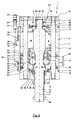
- Fig. 1 shows a vehicle door pivoting drive 1 according to the invention in a longitudinal section.
- the vehicle door pivot drive 1 has a main body 2 with a housing 3, which forms a working cylinder 4.
- the working cylinder 4 is formed with a circular disk-shaped bottom plate 5 and a circular disk-shaped cover plate 6 and a hollow cylindrical sleeve 7, which are arranged coaxially to a longitudinal axis 8 and are firmly connected to each other while sealing an interior 9.
- the end regions of the sleeve 7 each enclose with a suitable fit a collar 10, 11 of the bottom plate 5 and the cover plate 6 with interposition of sealing elements 12, 13 in the form of O-rings, which are received in annular grooves of the collar 10, 11.
- the interior 9 of the working cylinder 4 is divided by a radially outwardly relative to the sleeve 7 sealed actuating piston 14 in working chambers 15, 16, wherein in the operating position according to Fig. 1 the volume of the working chamber 15 is minimal, since the actuating piston 14 rests against the bottom plate 5.
- This operating position correlates with a closed position of the vehicle door. If the actuating piston 14 is displaced upward while maximizing the volume of the working chamber 15 so that the actuating piston 14 comes into contact with the cover plate 6, the open position of the vehicle door is reached.
- the working cylinder 4 here by the sleeve 7, the actuating piston 14 is guided in an axial direction of adjustment 17, ie along the longitudinal axis 8.
- two guide rods 18, 19 extend through the working cylinder 4 and the inner space 9.
- the guide rods 18, 19 are oriented parallel to the longitudinal axis 8 and are located, seen in a cross section, at the same distance from the Longitudinal axis 8 on diametrically opposite positions.
- the guide rods 18, 19 have in the region of the interior 9 a cylindrical lateral surface.
- the guide rods 18, 19 are each firmly connected in one end region with the bottom plate 5 and in another end region with the cover plate 6.
- the bottom plate 5 has two threaded holes into which the associated end portions of the guide rods 18, 19 are screwed.
- the cover plate 6 has two through holes 20, 21, through which the guide rods 18, 19 extend through into outer recesses 22, 23.
- the guide rods 18, 19 each have an external thread, on which lock nuts 24th , 25 are screwed.
- tightening of the lock nuts 24, 25 can cause bracing of the guide rods 18, 19, whereby an axial clamping of the sleeve 7 takes place between the base plate 5 and the cover plate 6, so that an additional attachment between the base plate 5 and cover plate 6 on the sleeve 7 is not mandatory.
- the adjusting piston 14 has in the region of its contact surface to the sleeve 7 on the working chambers 15, 16 facing sides in each case an annular groove in which sealing elements 26, 27 are accommodated, which ensure a seal against the sleeve 7, whereby a transfer of fluid between the Working chambers 15, 16 is prevented via the guide surface between the adjusting piston 14 and sleeve 7.
- the guide rods 18, 19 extend with their cylindrical lateral surface through corresponding passage recesses 28, 29 of the actuating piston 14 therethrough. Between control piston 14 and guide rods 18, 19 are each plain bearing sleeves 30, 31 and in the axial direction between the plain bearing sleeves 30, 31, a sealing element 32, here an O-ring for sealing the working chambers 15, 16 against each other interposed.
- a drive member 33 extends through the interior 9.
- the drive member 33 is rotatably mounted both in the bottom plate 5 and in the cover plate 6, wherein in the bottom plate 5 and / or the cover plate 6 also an axial bearing of the drive member 33rd can be done.
- a drive pin 34 projects through the bottom plate 5 out of the housing 3.
- the drive member 33 with other drive elements of the vehicle door such as a rotary column, or directly the vehicle door, rotatably coupled to a rotation or Pivoting the drive member 33 to the vehicle door, possibly with a translation by an additional intermediate transmission to transfer.
- the bottom plate 5 has a passage recess 35. With the interposition of a scraper 36 and a collar bush 37, the drive member 33 is guided in the through-hole 35 of the bottom plate 5.
- the collar bush 37 is supported via a spacer 38, a damping disk 39 and a further spacer 40 on a shoulder 41 of the drive member 33.
- the damping disk 39 is rotatably coupled to the drive member 33 and has a circumferentially oriented slot.
- the slot is a connection for acting on the working chamber 15 completely free, while the end portions of the slot close to approach the open position or the closed position partially or increasingly with the introduction of a throttling for a Cushioning.
- the cover plate 6 also has a passage recess 42 for supporting the drive member 33 without the drive member 33 passing through the cover plate 6. With the interposition of an axial support plate 43, an end face of the drive member 33 is supported on a bottom 44 of the passage recess 42.
- a damping disk 46 is coupled in a rotationally fixed manner to the drive member 33, by way of which a cushioning for the fluidic admission of the working chamber 15 can be accomplished, as previously described is.
- the coupling mechanism 47 is formed as a spindle drive, as this is described in detail in the above-mentioned publications, which in addition to further Details are pointed out.
- the Drive member 33 in the interior 9 equipped with two screw threads 49, 50 which extend helically around the longitudinal axis 8.
- Rollers 51, 52 roll on the screw threads, which are rotatable about axes of rotation which are vertical to the plane of the drawing Fig. 1 are oriented, are mounted relative to the actuating piston 14.
- a compensation of the axial movement of the actuating piston 14 with respect to the non-axially moving drive member 33 with a rolling movement of the rollers can take place via the rollers 51, 52.
- a conversion of the axial adjusting movement 17 of the actuating piston 14 in a pivoting movement 48 of the drive member 33 between actuator piston 14 and drive member 33 is a guide sleeve 53 and sealing elements 54, 55 interposed, in order to avoid that a fluidic pressure equalization between the working chambers 15, 16 via the recess of the actuating piston 14, through which the drive member 33 is passed.
- the seal 54 has a non-circular inner contour, which corresponds to the outer contour of the drive member 33 with the coiled screw threads 49, 50, to allow a seal against the drive member 33.
- the seal 54 and the attachment of the same via the guide sleeve 53 in the actuating piston 14 is on the above cited document DE 10 2007 025 375 B4 directed.
- the drive member 33 has seen from the drive pin 34 before the start of the screw threads 49, 50 an annular groove with arranged therein sealing element 56 which comes to seal against an inner surface of the actuating piston 14 in the closed position.
- the drive member 33 has an attached sealing sleeve 57.
- the sealing sleeve 57 has radially outboard an annular groove into which a sealing element 58 is inserted. If the actuating piston 14 reaches the region of the closed position, the sealing element 58 comes into contact with an inner surface of the guide sleeve 53 in order to ensure an additional seal.
- the vehicle door pivot drive 1 is equipped with a sensor 59.
- the sensor 59 is formed with a permanent magnet 60, a waveguide 61, a transducer 62, and a terminal 76.
- the waveguide 61 is made of a magnetostrictive material.
- here can be a tube from a Nickel-iron alloy can be used, through which a copper conductor is threaded.
- a nickel wire can be used.
- a circular magnetic field is generated by a short current pulse through the copper conductor or the nickel wire, which is bundled due to soft magnetic properties of the waveguide 61 in this.
- the permanent magnet 60 serves as a position transmitter for the actuating piston 14.
- the magnetic field lines of the permanent magnet 60 extend at right angles to the circular magnetic field of the waveguide 61 and are bundled in the waveguide 61.
- an elastic deformation by magnetostriction arises in the microregion of the crystal structure of the waveguide 61, producing a mechanical wave propagating on both sides.
- the current to the end of the waveguide 61 wave is damped away there, while the current to the converter 62 wave generated by reversing the magnetostrictive effect in the transducer an electrical measurement signal, which correlates with the position of the permanent magnet 60, so the adjusting piston 14.
- Alternative designs do not attenuate the signal in the direction of the end region of the waveguide 61 facing away from the transducer, but allow it to be reflected there. This can have the advantage that the reflected signal can be used for error analysis and temperature compensation.
- a sensor 59 which can be used by way of example within the scope of the invention is an under the designation "Temposonics” (registered trademark), C series, basic sensor analog (measuring length 52-250 mm) of the company MTS Sensor Technology GmbH & Co. KG, 58513 Lüdenscheid, Germany distributed sensor.
- the guide rod 19 has a central longitudinal bore, which is formed here as a blind hole 77, which extends to the bottom plate 5.
- the waveguide 61 is arranged to form a slight radial mounting clearance, which, as in Fig. 1 can extend over the entire interior 9, but at least up to the position of the permanent magnet 60 in the in Fig. 1 effective closed position.
- the sensor 59 has a housing 63, into which the waveguide 61 enters in the region of an end face, while the connection 76 is provided in the region of the opposite end face.
- the housing ensures an IP protection class, in particular IP 30.
- the housing 63 is supplied with the sensor 59 and an integral part of the same.
- the housing 63 is arranged in a housing 64.
- the housing 64 is attached to the housing 3 and firmly connected thereto.
- the fixed connection is made by a transverse to the longitudinal axis of the sensor oriented grub screw 65.
- a sleeve-like approach of the housing 64 is receiving in a corresponding recess of the cover plate 6, wherein between approach and cover plate 6, a sealing element, here an O-ring, interposed for the purpose of sealing is.
- the housing 64 has a standardized or standardized connection 66 for a plug 67 for an electrical supply line and / or an output line of the sensor 59, these lines then being coupled to the terminal 76 of the sensor 59.
- the guide rod 19 is not magnetic.
- This can for example be made of an austenitic stainless steel, plastic or an alloy with a high nickel content.
- the sensor 59 may generate an analog output signal in the range of 0.1-4.9V.
- the permanent magnet 60 moves along the guide rod 19 and thus along the waveguide 61, so that the sensor 59 generates an output signal corresponding to the adjusting movement 17, which can be processed by a control unit.
- This control unit may be part of the sensor 59, be arranged in the base body 2 or be arranged externally and in addition to the evaluation of the signal further purposes this.
- Fig. 2 shows a highly schematic block diagram for a method according to the invention for operating a vehicle door control with a fluidic vehicle door pivot drive 1:
- step 68 takes place, for example, via a hydraulic or pneumatic vehicle door control circuit according to the above-mentioned prior art, an admission of the working chambers 15, 16 of the vehicle door pivot drive 1 with a change in the pressure difference in the working chambers 15, 16th
- a method step 69 the measurement signal of the sensor 59 is detected and evaluated in the form of the determination of a travel X, that is to say a coordinate along the axial adjustment movement 17.
- a speed signal V for the actuating movement 17 is determined from the travel X, for example via a differentiation according to time or suitable filtering.
- an error signal for improper operation of the vehicle door control is determined.
- an error can be concluded if a pressure change is predetermined in method step 68, but it is determined in a method step 69 that there is no change in the adjustment path X or no sufficient change thereof.
- the adjusting piston may be blocked or jammed, be clogged a fluidic line or have a leak.
- suitable control measures can be taken automatically in order to counteract this error.
- an error signal can be generated optically or acoustically.
- a subsequent method step 72 it can be compared whether the adjusting movement 17 corresponds to a desired setting movement. For example, it can be checked whether a predetermined travel X and / or a predetermined actuating speed V are given at a given time. On the basis of this comparison, a regulation of the pressure conditions can then take place in that the vehicle door control circuit is then regulated again in the method step 68 that is carried out in such a way that there is a pressure change which should compensate for deviations determined in the comparison.
- a method step 73 it can be determined whether the vehicle door is approaching an end position, that is to say the open or closed position. For example, it can be determined whether the travel X corresponds to the travel for the open position or the closed position with a predetermined surrounding area around this position. If this is the case, the end position damping can be controlled or regulated, for example, by activating a throttle or by changing a throttle characteristic.
- a method step 74 it can be determined whether an obstacle blocks the opening or closing movement of the vehicle door. This can be detected automatically, for example, if in method step 68 a pressure difference is controlled, with which a change of the travel X or an adjustment speed V would occur, which then actually does not take place or to a reduced extent. Will such a Blocking or a resistance detected for the vehicle door, an appropriate control measure or regulatory action can be initiated. It is possible that the movement of the vehicle door is stopped, a pressure difference is eliminated or the direction of movement of the vehicle door is reversed.
- a further method step 75 is carried out only when the drive member 33 executes a pure pivoting movement for a first axial adjusting movement 17 of the adjusting piston, while an axial adjusting movement of the drive member 33 is generated for a different range of the axial adjusting movement for the purpose of locking or unlocking the vehicle door.
- this method step 75 it is checked whether the travel X is in the first-mentioned setting range, which can be used to detect that the vehicle door is being swiveled. If, on the other hand, it is detected that the travel X lies in the second setting range, it can be automatically detected that a locking or unlocking movement is being carried out.
- a control unit may be responsible, which is part of the vehicle door pivot drive 1, part of the sensor 59 or disposed elsewhere in the vehicle door control circuit.
- Fig. 3 shows an embodiment of a vehicle door pivoting drive 1 according to the invention, in principle Fig. 1 equivalent.
- the sensor 59 is integrated in other ways.
- the sensor 59 has a permanent magnet 60 arranged on the adjusting piston 14 as well as a waveguide 61 with a converter 62 and a connection 76 Fig. 1
- the waveguide 61 is not integrated into the guide rod 18, but the waveguide 61, the transducer 62 and the terminal 76 belong to a mounted externally on the housing 3 or flanged sensor unit 78.
- the sensor unit 78 is to a sleeve 7th mounted rail 79, so that the sensor unit 78 is displaced in the axial direction and then with Screws 80, 81 can be fixed to the rail 79.
- the axial position of the sensor unit 78 is thereby preferably adjusted such that the waveguide 61 covers the region of the axial adjusting movement of the actuating piston 14 in the axial direction.
- the rail 79 may be formed integrally with the sleeve 7.
- the rail 79 may also be made separately from the sleeve 7 and secured to the sleeve 7.
Landscapes
- Power-Operated Mechanisms For Wings (AREA)
Priority Applications (1)
| Application Number | Priority Date | Filing Date | Title |
|---|---|---|---|
| PL12180508T PL2562342T3 (pl) | 2011-08-24 | 2012-08-15 | Płynowy napęd obrotowy drzwi pojazdu |
Applications Claiming Priority (1)
| Application Number | Priority Date | Filing Date | Title |
|---|---|---|---|
| DE102011052961.6A DE102011052961B4 (de) | 2011-08-24 | 2011-08-24 | Fluidischer Fahrzeugtür-Schwenkantrieb |
Publications (3)
| Publication Number | Publication Date |
|---|---|
| EP2562342A2 true EP2562342A2 (fr) | 2013-02-27 |
| EP2562342A3 EP2562342A3 (fr) | 2014-12-17 |
| EP2562342B1 EP2562342B1 (fr) | 2018-01-17 |
Family
ID=46682734
Family Applications (1)
| Application Number | Title | Priority Date | Filing Date |
|---|---|---|---|
| EP12180508.9A Active EP2562342B1 (fr) | 2011-08-24 | 2012-08-15 | Commande fluidique pivotante d'une porte de véhicule |
Country Status (4)
| Country | Link |
|---|---|
| EP (1) | EP2562342B1 (fr) |
| DE (1) | DE102011052961B4 (fr) |
| ES (1) | ES2666296T3 (fr) |
| PL (1) | PL2562342T3 (fr) |
Cited By (2)
| Publication number | Priority date | Publication date | Assignee | Title |
|---|---|---|---|---|
| DE102013100003A1 (de) | 2013-01-02 | 2014-07-03 | Reinhold Schulte | Aufhängung für eine Flügeltür eines Fahrzeugs |
| DE102013100002A1 (de) | 2013-01-02 | 2014-07-17 | Reinhold Schulte | Antriebseinrichtung für eine Flügeltür eines Busses |
Families Citing this family (4)
| Publication number | Priority date | Publication date | Assignee | Title |
|---|---|---|---|---|
| JP2015507158A (ja) * | 2012-02-09 | 2015-03-05 | ムーグ インコーポレーテッド | ロータリー・アクチュエータ |
| DE102012103638B4 (de) | 2012-04-25 | 2015-07-09 | Reinhold Schulte | Fluidischer Fahrzeugtür-Schwenkantrieb |
| ES2760543T3 (es) | 2016-12-22 | 2020-05-14 | Reinhold Schulte | Dispositivo de accionamiento de puerta de vehículo |
| CN110552574B (zh) * | 2019-08-29 | 2021-03-30 | 广东东箭汽车科技股份有限公司 | 气压式撑杆和汽车 |
Citations (13)
| Publication number | Priority date | Publication date | Assignee | Title |
|---|---|---|---|---|
| DE2062135A1 (de) | 1970-12-17 | 1972-07-06 | Gebr. Bode & Co Vorm. Wegmann & Co, 3500 Kassel-Bettenhausen | Verriegelungsvorrichtung für den Türflügel einer Schwingtür, der mit Hilfe einer Drehsäule verschwenkt wird |
| EP0279236A1 (fr) | 1987-02-20 | 1988-08-24 | Gebrüder Bode & Co. GmbH | Dispositif d'actionnnement rotatif pour portes pivotantes en particulier pour véhicules |
| DE3705369A1 (de) | 1987-02-20 | 1988-09-01 | Bode & Co Geb | Drehantrieb zum bewegen eines schwenktuerfluegels, insbesondere an fahrzeugen |
| DE4007162A1 (de) | 1990-03-07 | 1991-09-12 | Brose Fahrzeugteile | Vorrichtung zum automatischen oeffnen und schliessen von schwenkbaren klappen, hauben und tueren |
| DE102006031447A1 (de) | 2006-07-07 | 2008-01-10 | Dr. Johannes Heidenhain Gmbh | Winkelmesseinrichtung |
| DE102006031477B4 (de) | 2006-07-07 | 2008-04-17 | Daimler Ag | Drehantrieb für schwenkbare Türflügel, insbesondere für Fahrzeugtüren |
| DE102008009558B3 (de) | 2008-02-06 | 2009-04-02 | Reinhold Schulte | Verriegelung |
| DE102007059564A1 (de) | 2007-12-11 | 2009-06-25 | Stabilus Gmbh | Antriebseinrichtung |
| DE102008011315A1 (de) | 2008-02-27 | 2009-09-24 | Daimler Ag | Pneumatische Fahrzeugtürsteuerung |
| DE102008034994B3 (de) | 2008-07-25 | 2009-11-12 | Daimler Ag | Drehantrieb für schwenkbare Türflügel |
| DE102008011316B4 (de) | 2008-02-27 | 2010-01-07 | Daimler Ag | Handnotschaltung für Pneumatiksysteme |
| DE102006053730B4 (de) | 2006-11-15 | 2010-05-06 | Stabilus Gmbh | Antriebseinrichtung |
| DE102007025375B4 (de) | 2007-05-31 | 2011-03-03 | Schulte, Reinhold, Dipl.-Ing. | Spindeldichtung |
Family Cites Families (8)
| Publication number | Priority date | Publication date | Assignee | Title |
|---|---|---|---|---|
| DE102005005011A1 (de) * | 2005-02-03 | 2006-08-10 | Hartmann-Exact Gmbh | Hydraulikzylinder zur Betätigung eines Cabriolet-Verdeckes |
| DE102006003695B4 (de) * | 2006-01-26 | 2009-12-03 | Rehau Ag + Co | Hydraulikmodul zum Öffnen und/oder Schließen einer Fahrzeugheckklappe |
| DE102006047966A1 (de) * | 2006-07-07 | 2008-01-10 | Asm Automation Sensorik Messtechnik Gmbh | Gleitelement mit Positionsgeber |
| DE102009027794B3 (de) * | 2009-07-17 | 2010-10-28 | Reinhold Schulte | Stelleinrichtung für eine Verschwenkung einer Klappe eines Fahrzeugs |
| DE102010002625B4 (de) * | 2010-03-05 | 2013-07-18 | Reinhold Schulte | Hydraulische Stelleinrichtung für einen Türflügel eines Omnibusses |
| DE102011001003B4 (de) * | 2011-03-01 | 2014-05-15 | Reinhold Schulte | Fahrzeugtür-Steuerkreis |
| EP2503086B1 (fr) | 2011-03-22 | 2016-03-16 | Reinhold Schulte | Groupe de circuit d'entraînement pour une portière de véhicule |
| EP2543807B2 (fr) * | 2011-07-06 | 2020-03-18 | Isaf Bus Components S.r.l. | Actionneur rotatif pour déplacer une porte battante pivotante, en particulier dans des véhicules |
-
2011
- 2011-08-24 DE DE102011052961.6A patent/DE102011052961B4/de not_active Expired - Fee Related
-
2012
- 2012-08-15 PL PL12180508T patent/PL2562342T3/pl unknown
- 2012-08-15 EP EP12180508.9A patent/EP2562342B1/fr active Active
- 2012-08-15 ES ES12180508.9T patent/ES2666296T3/es active Active
Patent Citations (13)
| Publication number | Priority date | Publication date | Assignee | Title |
|---|---|---|---|---|
| DE2062135A1 (de) | 1970-12-17 | 1972-07-06 | Gebr. Bode & Co Vorm. Wegmann & Co, 3500 Kassel-Bettenhausen | Verriegelungsvorrichtung für den Türflügel einer Schwingtür, der mit Hilfe einer Drehsäule verschwenkt wird |
| EP0279236A1 (fr) | 1987-02-20 | 1988-08-24 | Gebrüder Bode & Co. GmbH | Dispositif d'actionnnement rotatif pour portes pivotantes en particulier pour véhicules |
| DE3705369A1 (de) | 1987-02-20 | 1988-09-01 | Bode & Co Geb | Drehantrieb zum bewegen eines schwenktuerfluegels, insbesondere an fahrzeugen |
| DE4007162A1 (de) | 1990-03-07 | 1991-09-12 | Brose Fahrzeugteile | Vorrichtung zum automatischen oeffnen und schliessen von schwenkbaren klappen, hauben und tueren |
| DE102006031447A1 (de) | 2006-07-07 | 2008-01-10 | Dr. Johannes Heidenhain Gmbh | Winkelmesseinrichtung |
| DE102006031477B4 (de) | 2006-07-07 | 2008-04-17 | Daimler Ag | Drehantrieb für schwenkbare Türflügel, insbesondere für Fahrzeugtüren |
| DE102006053730B4 (de) | 2006-11-15 | 2010-05-06 | Stabilus Gmbh | Antriebseinrichtung |
| DE102007025375B4 (de) | 2007-05-31 | 2011-03-03 | Schulte, Reinhold, Dipl.-Ing. | Spindeldichtung |
| DE102007059564A1 (de) | 2007-12-11 | 2009-06-25 | Stabilus Gmbh | Antriebseinrichtung |
| DE102008009558B3 (de) | 2008-02-06 | 2009-04-02 | Reinhold Schulte | Verriegelung |
| DE102008011316B4 (de) | 2008-02-27 | 2010-01-07 | Daimler Ag | Handnotschaltung für Pneumatiksysteme |
| DE102008011315A1 (de) | 2008-02-27 | 2009-09-24 | Daimler Ag | Pneumatische Fahrzeugtürsteuerung |
| DE102008034994B3 (de) | 2008-07-25 | 2009-11-12 | Daimler Ag | Drehantrieb für schwenkbare Türflügel |
Cited By (2)
| Publication number | Priority date | Publication date | Assignee | Title |
|---|---|---|---|---|
| DE102013100003A1 (de) | 2013-01-02 | 2014-07-03 | Reinhold Schulte | Aufhängung für eine Flügeltür eines Fahrzeugs |
| DE102013100002A1 (de) | 2013-01-02 | 2014-07-17 | Reinhold Schulte | Antriebseinrichtung für eine Flügeltür eines Busses |
Also Published As
| Publication number | Publication date |
|---|---|
| DE102011052961B4 (de) | 2017-01-26 |
| DE102011052961A1 (de) | 2013-02-28 |
| PL2562342T3 (pl) | 2018-08-31 |
| EP2562342B1 (fr) | 2018-01-17 |
| EP2562342A3 (fr) | 2014-12-17 |
| ES2666296T3 (es) | 2018-05-03 |
Similar Documents
| Publication | Publication Date | Title |
|---|---|---|
| EP2562342B1 (fr) | Commande fluidique pivotante d'une porte de véhicule | |
| EP3299561B1 (fr) | Dispositif de réglage | |
| DE102010002625B4 (de) | Hydraulische Stelleinrichtung für einen Türflügel eines Omnibusses | |
| DE102006030986B4 (de) | Vorrichtung und Verfahren zur Steuerung einer Fahrzeugklappe oder einer Fahrzeugtür | |
| EP3247853B1 (fr) | Serrure de véhicule automobile | |
| EP2503086B1 (fr) | Groupe de circuit d'entraînement pour une portière de véhicule | |
| EP2769041B1 (fr) | Dispositif d'entrainement pour dispositifs d'accès et de sortie de véhicules de transport public | |
| EP3572607B1 (fr) | Dispositif d'entraînement pour portes de véhicule | |
| EP1936091A2 (fr) | Actionnement de porte ou de fenêtre | |
| DE10259925A1 (de) | Türantrieb | |
| DE102017115586A1 (de) | Antriebsanordnung | |
| DE19954505A1 (de) | Aktive Lenkvorrichtung | |
| EP2899091B1 (fr) | Module de porte oscillante coulissante doté d'un verrouillage décentré surveillé et son procédé de fonctionnement | |
| DE102012103638B4 (de) | Fluidischer Fahrzeugtür-Schwenkantrieb | |
| DE102018132666A1 (de) | Aufstellvorrichtung für ein kraftfahrzeugtürelement | |
| EP3714126A1 (fr) | Procédé de fonctionnement d'un système d'entraînement pour un ouvrant de carrosserie d'un véhicule automobile | |
| DE102012209146A1 (de) | Betätigbare Klappenanordnung | |
| DE202007002404U1 (de) | Steuersystem zur Steuerung eines Fensterhebers eines Kraftfahrzeugs und Fensterhebersystem | |
| EP3971456A1 (fr) | Détection de la position de soupape de réglage | |
| EP3788224B1 (fr) | Système d'entraînement de véhicule automobile | |
| DE202012103908U1 (de) | Drehgelenk mit Drehwinkelmessung | |
| DE202007006789U1 (de) | Blockiervorrichtung und zugeordneter fluidbetätigter Linearantrieb | |
| DE102012210814B4 (de) | Antrieb zum Öffnen und/oder Schließen eines beweglichen Flügels einer Tür oder eines Fensters sowie Verfahren zum Betrieb dieses Antriebs | |
| DE10207033A1 (de) | Antriebsmittel zum Schwenken einer an einem Tragarm schwenkbar gelagerten Flugzeugtür | |
| DE102018206583B4 (de) | Antriebseinheit für einen Schwenk- oder Schiebeflügel und Drehpositionserfassungsverfahren in einer Antriebseinheit |
Legal Events
| Date | Code | Title | Description |
|---|---|---|---|
| PUAI | Public reference made under article 153(3) epc to a published international application that has entered the european phase |
Free format text: ORIGINAL CODE: 0009012 |
|
| AK | Designated contracting states |
Kind code of ref document: A2 Designated state(s): AL AT BE BG CH CY CZ DE DK EE ES FI FR GB GR HR HU IE IS IT LI LT LU LV MC MK MT NL NO PL PT RO RS SE SI SK SM TR |
|
| AX | Request for extension of the european patent |
Extension state: BA ME |
|
| PUAL | Search report despatched |
Free format text: ORIGINAL CODE: 0009013 |
|
| AK | Designated contracting states |
Kind code of ref document: A3 Designated state(s): AL AT BE BG CH CY CZ DE DK EE ES FI FR GB GR HR HU IE IS IT LI LT LU LV MC MK MT NL NO PL PT RO RS SE SI SK SM TR |
|
| AX | Request for extension of the european patent |
Extension state: BA ME |
|
| RIC1 | Information provided on ipc code assigned before grant |
Ipc: E05F 15/04 20060101AFI20141112BHEP |
|
| 17P | Request for examination filed |
Effective date: 20150216 |
|
| RBV | Designated contracting states (corrected) |
Designated state(s): AL AT BE BG CH CY CZ DE DK EE ES FI FR GB GR HR HU IE IS IT LI LT LU LV MC MK MT NL NO PL PT RO RS SE SI SK SM TR |
|
| REG | Reference to a national code |
Ref country code: DE Ref legal event code: R079 Ref document number: 502012012019 Country of ref document: DE Free format text: PREVIOUS MAIN CLASS: E05F0015020000 Ipc: E05F0015540000 |
|
| RIC1 | Information provided on ipc code assigned before grant |
Ipc: E05F 15/54 20150101AFI20170817BHEP |
|
| GRAP | Despatch of communication of intention to grant a patent |
Free format text: ORIGINAL CODE: EPIDOSNIGR1 |
|
| GRAS | Grant fee paid |
Free format text: ORIGINAL CODE: EPIDOSNIGR3 |
|
| INTG | Intention to grant announced |
Effective date: 20170928 |
|
| GRAA | (expected) grant |
Free format text: ORIGINAL CODE: 0009210 |
|
| AK | Designated contracting states |
Kind code of ref document: B1 Designated state(s): AL AT BE BG CH CY CZ DE DK EE ES FI FR GB GR HR HU IE IS IT LI LT LU LV MC MK MT NL NO PL PT RO RS SE SI SK SM TR |
|
| REG | Reference to a national code |
Ref country code: GB Ref legal event code: FG4D Free format text: NOT ENGLISH |
|
| REG | Reference to a national code |
Ref country code: CH Ref legal event code: EP |
|
| REG | Reference to a national code |
Ref country code: IE Ref legal event code: FG4D Free format text: LANGUAGE OF EP DOCUMENT: GERMAN |
|
| REG | Reference to a national code |
Ref country code: DE Ref legal event code: R096 Ref document number: 502012012019 Country of ref document: DE Ref country code: AT Ref legal event code: REF Ref document number: 964544 Country of ref document: AT Kind code of ref document: T Effective date: 20180215 |
|
| REG | Reference to a national code |
Ref country code: ES Ref legal event code: FG2A Ref document number: 2666296 Country of ref document: ES Kind code of ref document: T3 Effective date: 20180503 |
|
| REG | Reference to a national code |
Ref country code: NL Ref legal event code: MP Effective date: 20180117 |
|
| REG | Reference to a national code |
Ref country code: LT Ref legal event code: MG4D |
|
| PG25 | Lapsed in a contracting state [announced via postgrant information from national office to epo] |
Ref country code: NL Free format text: LAPSE BECAUSE OF FAILURE TO SUBMIT A TRANSLATION OF THE DESCRIPTION OR TO PAY THE FEE WITHIN THE PRESCRIBED TIME-LIMIT Effective date: 20180117 |
|
| PG25 | Lapsed in a contracting state [announced via postgrant information from national office to epo] |
Ref country code: HR Free format text: LAPSE BECAUSE OF FAILURE TO SUBMIT A TRANSLATION OF THE DESCRIPTION OR TO PAY THE FEE WITHIN THE PRESCRIBED TIME-LIMIT Effective date: 20180117 Ref country code: NO Free format text: LAPSE BECAUSE OF FAILURE TO SUBMIT A TRANSLATION OF THE DESCRIPTION OR TO PAY THE FEE WITHIN THE PRESCRIBED TIME-LIMIT Effective date: 20180417 Ref country code: FI Free format text: LAPSE BECAUSE OF FAILURE TO SUBMIT A TRANSLATION OF THE DESCRIPTION OR TO PAY THE FEE WITHIN THE PRESCRIBED TIME-LIMIT Effective date: 20180117 Ref country code: LT Free format text: LAPSE BECAUSE OF FAILURE TO SUBMIT A TRANSLATION OF THE DESCRIPTION OR TO PAY THE FEE WITHIN THE PRESCRIBED TIME-LIMIT Effective date: 20180117 Ref country code: CY Free format text: LAPSE BECAUSE OF FAILURE TO SUBMIT A TRANSLATION OF THE DESCRIPTION OR TO PAY THE FEE WITHIN THE PRESCRIBED TIME-LIMIT Effective date: 20180117 |
|
| REG | Reference to a national code |
Ref country code: FR Ref legal event code: PLFP Year of fee payment: 7 |
|
| PG25 | Lapsed in a contracting state [announced via postgrant information from national office to epo] |
Ref country code: LV Free format text: LAPSE BECAUSE OF FAILURE TO SUBMIT A TRANSLATION OF THE DESCRIPTION OR TO PAY THE FEE WITHIN THE PRESCRIBED TIME-LIMIT Effective date: 20180117 Ref country code: SE Free format text: LAPSE BECAUSE OF FAILURE TO SUBMIT A TRANSLATION OF THE DESCRIPTION OR TO PAY THE FEE WITHIN THE PRESCRIBED TIME-LIMIT Effective date: 20180117 Ref country code: IS Free format text: LAPSE BECAUSE OF FAILURE TO SUBMIT A TRANSLATION OF THE DESCRIPTION OR TO PAY THE FEE WITHIN THE PRESCRIBED TIME-LIMIT Effective date: 20180517 Ref country code: GR Free format text: LAPSE BECAUSE OF FAILURE TO SUBMIT A TRANSLATION OF THE DESCRIPTION OR TO PAY THE FEE WITHIN THE PRESCRIBED TIME-LIMIT Effective date: 20180418 Ref country code: BG Free format text: LAPSE BECAUSE OF FAILURE TO SUBMIT A TRANSLATION OF THE DESCRIPTION OR TO PAY THE FEE WITHIN THE PRESCRIBED TIME-LIMIT Effective date: 20180417 Ref country code: RS Free format text: LAPSE BECAUSE OF FAILURE TO SUBMIT A TRANSLATION OF THE DESCRIPTION OR TO PAY THE FEE WITHIN THE PRESCRIBED TIME-LIMIT Effective date: 20180117 |
|
| PG25 | Lapsed in a contracting state [announced via postgrant information from national office to epo] |
Ref country code: MT Free format text: LAPSE BECAUSE OF FAILURE TO SUBMIT A TRANSLATION OF THE DESCRIPTION OR TO PAY THE FEE WITHIN THE PRESCRIBED TIME-LIMIT Effective date: 20180117 |
|
| REG | Reference to a national code |
Ref country code: DE Ref legal event code: R097 Ref document number: 502012012019 Country of ref document: DE |
|
| PG25 | Lapsed in a contracting state [announced via postgrant information from national office to epo] |
Ref country code: RO Free format text: LAPSE BECAUSE OF FAILURE TO SUBMIT A TRANSLATION OF THE DESCRIPTION OR TO PAY THE FEE WITHIN THE PRESCRIBED TIME-LIMIT Effective date: 20180117 Ref country code: AL Free format text: LAPSE BECAUSE OF FAILURE TO SUBMIT A TRANSLATION OF THE DESCRIPTION OR TO PAY THE FEE WITHIN THE PRESCRIBED TIME-LIMIT Effective date: 20180117 Ref country code: EE Free format text: LAPSE BECAUSE OF FAILURE TO SUBMIT A TRANSLATION OF THE DESCRIPTION OR TO PAY THE FEE WITHIN THE PRESCRIBED TIME-LIMIT Effective date: 20180117 |
|
| PLBE | No opposition filed within time limit |
Free format text: ORIGINAL CODE: 0009261 |
|
| STAA | Information on the status of an ep patent application or granted ep patent |
Free format text: STATUS: NO OPPOSITION FILED WITHIN TIME LIMIT |
|
| PG25 | Lapsed in a contracting state [announced via postgrant information from national office to epo] |
Ref country code: DK Free format text: LAPSE BECAUSE OF FAILURE TO SUBMIT A TRANSLATION OF THE DESCRIPTION OR TO PAY THE FEE WITHIN THE PRESCRIBED TIME-LIMIT Effective date: 20180117 Ref country code: CZ Free format text: LAPSE BECAUSE OF FAILURE TO SUBMIT A TRANSLATION OF THE DESCRIPTION OR TO PAY THE FEE WITHIN THE PRESCRIBED TIME-LIMIT Effective date: 20180117 Ref country code: SK Free format text: LAPSE BECAUSE OF FAILURE TO SUBMIT A TRANSLATION OF THE DESCRIPTION OR TO PAY THE FEE WITHIN THE PRESCRIBED TIME-LIMIT Effective date: 20180117 Ref country code: SM Free format text: LAPSE BECAUSE OF FAILURE TO SUBMIT A TRANSLATION OF THE DESCRIPTION OR TO PAY THE FEE WITHIN THE PRESCRIBED TIME-LIMIT Effective date: 20180117 |
|
| 26N | No opposition filed |
Effective date: 20181018 |
|
| PG25 | Lapsed in a contracting state [announced via postgrant information from national office to epo] |
Ref country code: SI Free format text: LAPSE BECAUSE OF FAILURE TO SUBMIT A TRANSLATION OF THE DESCRIPTION OR TO PAY THE FEE WITHIN THE PRESCRIBED TIME-LIMIT Effective date: 20180117 |
|
| PG25 | Lapsed in a contracting state [announced via postgrant information from national office to epo] |
Ref country code: MC Free format text: LAPSE BECAUSE OF FAILURE TO SUBMIT A TRANSLATION OF THE DESCRIPTION OR TO PAY THE FEE WITHIN THE PRESCRIBED TIME-LIMIT Effective date: 20180117 |
|
| REG | Reference to a national code |
Ref country code: CH Ref legal event code: PL |
|
| GBPC | Gb: european patent ceased through non-payment of renewal fee |
Effective date: 20180815 |
|
| PG25 | Lapsed in a contracting state [announced via postgrant information from national office to epo] |
Ref country code: LI Free format text: LAPSE BECAUSE OF NON-PAYMENT OF DUE FEES Effective date: 20180831 Ref country code: LU Free format text: LAPSE BECAUSE OF NON-PAYMENT OF DUE FEES Effective date: 20180815 Ref country code: CH Free format text: LAPSE BECAUSE OF NON-PAYMENT OF DUE FEES Effective date: 20180831 |
|
| REG | Reference to a national code |
Ref country code: BE Ref legal event code: MM Effective date: 20180831 |
|
| REG | Reference to a national code |
Ref country code: IE Ref legal event code: MM4A |
|
| PG25 | Lapsed in a contracting state [announced via postgrant information from national office to epo] |
Ref country code: IE Free format text: LAPSE BECAUSE OF NON-PAYMENT OF DUE FEES Effective date: 20180815 |
|
| PG25 | Lapsed in a contracting state [announced via postgrant information from national office to epo] |
Ref country code: BE Free format text: LAPSE BECAUSE OF NON-PAYMENT OF DUE FEES Effective date: 20180831 |
|
| REG | Reference to a national code |
Ref country code: AT Ref legal event code: MM01 Ref document number: 964544 Country of ref document: AT Kind code of ref document: T Effective date: 20180815 |
|
| PG25 | Lapsed in a contracting state [announced via postgrant information from national office to epo] |
Ref country code: GB Free format text: LAPSE BECAUSE OF NON-PAYMENT OF DUE FEES Effective date: 20180815 |
|
| PG25 | Lapsed in a contracting state [announced via postgrant information from national office to epo] |
Ref country code: AT Free format text: LAPSE BECAUSE OF NON-PAYMENT OF DUE FEES Effective date: 20180815 |
|
| PG25 | Lapsed in a contracting state [announced via postgrant information from national office to epo] |
Ref country code: HU Free format text: LAPSE BECAUSE OF FAILURE TO SUBMIT A TRANSLATION OF THE DESCRIPTION OR TO PAY THE FEE WITHIN THE PRESCRIBED TIME-LIMIT; INVALID AB INITIO Effective date: 20120815 Ref country code: PT Free format text: LAPSE BECAUSE OF FAILURE TO SUBMIT A TRANSLATION OF THE DESCRIPTION OR TO PAY THE FEE WITHIN THE PRESCRIBED TIME-LIMIT Effective date: 20180117 |
|
| PG25 | Lapsed in a contracting state [announced via postgrant information from national office to epo] |
Ref country code: MK Free format text: LAPSE BECAUSE OF NON-PAYMENT OF DUE FEES Effective date: 20180117 |
|
| P01 | Opt-out of the competence of the unified patent court (upc) registered |
Effective date: 20230529 |
|
| PGFP | Annual fee paid to national office [announced via postgrant information from national office to epo] |
Ref country code: ES Payment date: 20250917 Year of fee payment: 14 |
|
| PGFP | Annual fee paid to national office [announced via postgrant information from national office to epo] |
Ref country code: DE Payment date: 20250522 Year of fee payment: 14 |
|
| PGFP | Annual fee paid to national office [announced via postgrant information from national office to epo] |
Ref country code: PL Payment date: 20250801 Year of fee payment: 14 Ref country code: TR Payment date: 20250808 Year of fee payment: 14 Ref country code: IT Payment date: 20250829 Year of fee payment: 14 |
|
| PGFP | Annual fee paid to national office [announced via postgrant information from national office to epo] |
Ref country code: FR Payment date: 20250821 Year of fee payment: 14 |