EP2563555B1 - Appareil de prehension a elements de type poches remplies par une substance granulaire - Google Patents
Appareil de prehension a elements de type poches remplies par une substance granulaire Download PDFInfo
- Publication number
- EP2563555B1 EP2563555B1 EP11726495.2A EP11726495A EP2563555B1 EP 2563555 B1 EP2563555 B1 EP 2563555B1 EP 11726495 A EP11726495 A EP 11726495A EP 2563555 B1 EP2563555 B1 EP 2563555B1
- Authority
- EP
- European Patent Office
- Prior art keywords
- portions
- workpiece
- grasping
- shape
- contact
- Prior art date
- Legal status (The legal status is an assumption and is not a legal conclusion. Google has not performed a legal analysis and makes no representation as to the accuracy of the status listed.)
- Active
Links
Images








Classifications
-
- B—PERFORMING OPERATIONS; TRANSPORTING
- B25—HAND TOOLS; PORTABLE POWER-DRIVEN TOOLS; MANIPULATORS
- B25J—MANIPULATORS; CHAMBERS PROVIDED WITH MANIPULATION DEVICES
- B25J15/00—Gripping heads and other end effectors
- B25J15/08—Gripping heads and other end effectors having finger members
- B25J15/12—Gripping heads and other end effectors having finger members with flexible finger members
-
- B—PERFORMING OPERATIONS; TRANSPORTING
- B25—HAND TOOLS; PORTABLE POWER-DRIVEN TOOLS; MANIPULATORS
- B25J—MANIPULATORS; CHAMBERS PROVIDED WITH MANIPULATION DEVICES
- B25J15/00—Gripping heads and other end effectors
- B25J15/0023—Gripper surfaces directly activated by a fluid
-
- B—PERFORMING OPERATIONS; TRANSPORTING
- B65—CONVEYING; PACKING; STORING; HANDLING THIN OR FILAMENTARY MATERIAL
- B65G—TRANSPORT OR STORAGE DEVICES, e.g. CONVEYORS FOR LOADING OR TIPPING, SHOP CONVEYOR SYSTEMS OR PNEUMATIC TUBE CONVEYORS
- B65G47/00—Article or material-handling devices associated with conveyors; Methods employing such devices
- B65G47/74—Feeding, transfer, or discharging devices of particular kinds or types
- B65G47/90—Devices for picking-up and depositing articles or materials
-
- B—PERFORMING OPERATIONS; TRANSPORTING
- B66—HOISTING; LIFTING; HAULING
- B66C—CRANES; LOAD-ENGAGING ELEMENTS OR DEVICES FOR CRANES, CAPSTANS, WINCHES, OR TACKLES
- B66C1/00—Load-engaging elements or devices attached to lifting or lowering gear of cranes or adapted for connection therewith for transmitting lifting forces to articles or groups of articles
- B66C1/10—Load-engaging elements or devices attached to lifting or lowering gear of cranes or adapted for connection therewith for transmitting lifting forces to articles or groups of articles by mechanical means
- B66C1/42—Gripping members engaging only the external or internal surfaces of the articles
Definitions
- the invention relates to technology of a grasping apparatus capable of reliably grasping any of a plurality of types of workpieces of different shapes.
- JP-A-9-123082 describes a grasping apparatus provided with a contact portion capable of handling various outer shapes by encapsulating a large amount of granular substance inside a flexible membrane, and reducing the pressure in the membrane using a vacuum pump or the like, or canceling that pressure reduction.
- a contact portion is arranged at a tip end of a support device such as a robotic arm or the like. Also, with a grasping operation by the robotic arm or the like, the contact portion is made to abut against the workpiece or the like and conform to the shape of the workpiece or the like. Then the large amount of granular substance inside the membrane is held tightly and the shape of the contact portion is kept conformed to the shape of the workpiece.
- the contact portion is returned to its normal shape by canceling the reduced pressure state in the contact portion. Also, using such a related grasping apparatus enables the shape of the contact portion to match the outer shapes of various workpieces and the like. As a result, when handling a plurality of various workpieces having different outer shapes, the workpieces can be stably grasped.
- the contact portion of the related art is typically firmly fixed by a method such as adhesion so that it will not be displaced with respect to the robotic arm or the like.
- a method such as adhesion so that it will not be displaced with respect to the robotic arm or the like.
- it is not easy to replace the contact portion if it becomes damaged from abrasion or cutting or the like. Therefore, it is difficult to apply a grasping apparatus having a contact portion like that of the related art to a workpiece that has multiple edge portions or to a workpiece to which cutting dust is adhered.
- the invention thus provides a grasping apparatus i) that is provided with a contact portion that is very resistant to abrasion and cutting, that can maintain a good grasp, and that can be replaced easily, and ii) that is able to inhibit the contact portion from being displaced with respect to a portion that the contact portion attaches to, even though the contact portion is easy to replace.
- a first aspect of the invention relates to a grasping apparatus that includes a grasping portion for grasping a workpiece.
- This grasping portion includes i) pawl portions having a plurality of squeezing portions that squeeze the workpiece, and ii) contact portions, each of which has a bag member made of elastic material, and a granular substance that is filled in the bag member.
- the contact portions are attached to portions of the squeezing portions and arranged in use to contact the workpiece, and harden the granular substance while keeping the granular substance in an appropriate shape by increasing a volume ratio of the granular substance to an inner volume of the bag member.
- a retaining portion that has a concavo-convex shape is formed at a portion of each of the pawl portions to which the corresponding contact portion is attached.
- each of the contact portions may include an outer bag that is made of aramid fiber and that covers the bag member.
- This structure makes it possible to inhibit the contact portions from being displaced with respect to the squeezing portions, while ensuring the resistance of the contact portions to abrasion and cutting.
- the bag member may be housed inside the outer bag in a state relatively displaceable with respect to the outer bag.
- the bag member is able to accurately conform to the shape of the retaining portions, so the contact portions are able to be even more reliably inhibited from being displaced with respect to the squeezing portions.
- the granular substance may be ceramic fragments in which a shape of grains that make up the granular substance is a shape other than generally spherical.
- the contact portions can be made even harder when they are hardened, so the contact portions are able to be even more reliably inhibited from being displaced with respect to the squeezing portions.
- the granular substance may be such that the grains that are formed of artificial ceramic (so-called synthetic mullite) including at least Al 2 O 3 and SiO 2 , that has been crushed such that an average grain diameter is approximately 0.4 to 0.5 mm, inclusive, are shaped with edge portions.
- artificial ceramic so-called synthetic mullite
- the granular substance enables the contact portions to be made even harder when they are hardened. Also, the granular substance has a stable chemical property, so it inhibits the contact portions and the workpiece from rusting. Furthermore, the granular substance has a small specific gravity, so it enables the contact portions to be lightweight.
- a grasping apparatus 1 is an apparatus for grasping and holding a workpiece or the like, and includes a grasping portion 2, a control device 7, and evacuation equipment 8 and the like.
- the grasping portion 2 is a portion of the grasping apparatus 1 that directly grasps the workpiece, and includes a driving portion 3, a plurality of pawl portions 4 and 5, and a plurality of contact portions 6 and the like.
- the driving portion 3 is an apparatus that is provided with slider portions 3a and 3b of two systems, and is able to independently and reciprocally displace each of these slider portions 3a and 3b in the same axial direction.
- An electric actuator or the like that is provided with a reciprocating mechanism formed by a ball screw and nut and a motor or the like may be used as the driving portion 3.
- the pawl portions 4 and 5 are a pair of portions provided for squeezing the workpiece. That is, the pawl portions 4 and 5 are portions that squeeze and hold a workpiece arranged in a position between them.
- the shapes of the pawl portions 4 and 5 are set taking into account the shape and size of the workpiece to be grasped, and the stroke amount of the slider portions 3a and 3b and the like.
- the pawl portion 4 includes a support portion 4a and two squeezing portions 4b that protrude from the support portion 4a.
- the squeezing portions 4b are arranged a predetermined distance apart from one another.
- the surface of the pawl portion 4 on the side where the contact portion 6 is attached serves as an attaching surface 4g.
- the support portion 4a of the pawl portion 4 is fixed to the slider portion 3a.
- the control device 7 operates the driving portion 3 to slide the slider portion 3a such that the squeezing portions 4b move in a reciprocating manner in the sliding direction of the slider portion 3a (see FIG. 1 ).
- the pawl portion 5 includes a support portion 5a and one squeezing portion 5b that protrudes from the support portion 5a. Also, the surface of the pawl portion 5 on the side where the contact portion 6 is attached serves as an attaching surface 5g.
- the support portion 5a of the pawl portion 5 is fixed to the slider portion 3b.
- the control device 7 operates the driving portion 3 to slide the slider portion 3b such that the squeezing portion 5b moves in a reciprocating manner in the sliding direction of the slider portion 3b (see FIG. 1 ).
- the contact portion 6 is a portion of the grasping apparatus 1 that directly contacts the workpiece.
- the contact portion 6 is able to take on two opposite forms, i.e., one in which the shape of the contact portion 6 is able to flexibly deform and another in which the shape of the contact portion 6 is firmly maintained, with a single member.
- the contact portion 6 includes an elastic bag-shaped member and a granular substance that is filled into this bag-shaped member. Normally, the contact portion 6 takes on the form in which its shape is able to flexibly deform.
- the contact portion 6 is attached to the squeezing portions 4b and 5b of the pawl portions 4 and 5, and is connected to the evacuation equipment 8.
- the evacuation equipment 8 is means for making the contact portion 6 hard and soft in the grasping apparatus 1, and includes a vacuum pump 8a, vacuum ducts 8b, and an electromagnetic valve 8c and the like.
- the vacuum ducts 8b are connected to bag-shaped portions of the contact portions 6.
- the vacuum pump 8a is provided in the evacuation equipment 8, but a structure in which evacuating means other than the vacuum pump 8a (such as an ejector or the like) is provided is also possible.
- the means for making the contact portion hard and soft is not necessarily limited to the evacuation equipment. That is, any of various modes capable of making the contact portion hard and soft may be employed.
- the contact portion 6 becomes hard due to the grains that make up the granular substance that is filled inside the bag-shaped portion being held more firmly. Therefore, at this time, the contact portion 6 takes on the form in which its shape is firmly maintained.
- this contact portion 6 When this contact portion 6 is pressed, in a flexible state, against the workpiece by the squeezing pressure of the pawl portions 4 and 5, the contact portion 6 is able to fit into the concave portions and around the convex portions on the surface of the workpiece, thus enabling the contact portion 6 to conform to the shape of the outer surface of the workpiece.
- the contact portion 6 is able to be made hard in a shape corresponding to the shape of the outer surface of the workpiece by activating the evacuation equipment 8 while the contact portion 6 is conformed to the shape of the outer surface of the workpiece. Therefore, the hard contact portion 6 that corresponds to the shape of the outer surface of the workpiece can be formed.
- a workpiece 50 can be firmly grasped at three points by the contact portions 6 that are attached to the squeezing portions 4b and 5b.
- a stable grasping state that is able to withstand the workpiece 50 being swung around can be realized by a simple structure with few component parts.
- a mode is described in which the workpiece 50 is supported at three points by the grasping portion 2.
- the number of points at which the workpiece is supported in the grasping apparatus of the invention is not limited to this.
- the number of points at which the workpiece is supported may also be two, or four or more.
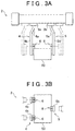
- the pawl portion 4 has the attaching surface 4g formed on the side to which the contact portion 6 attaches. Also, bolt holes 4c that are open to the attaching surface 4g are formed in the squeezing portion 4b of the pawl portion 4.
- bolts 9 are screwed into the bolt holes 4c.
- a retaining portion 10 is formed by the bolts 9 by screwing the bolts 9 in and adjusting them such that the tip ends of the bolts 9 protrude from the bolt holes 4c a predetermined amount from the attaching surface 4g.
- bolts 4d that serve as portions for hanging the contact portion 6 protrude from the attaching surface 4g on the squeezing portions 4b. Incidentally, here, the structure of the squeezing portions 4b of the pawl portion 4 is described.
- a similar retaining portion 10, not shown, is also formed on the squeezing portion 5b of the pawl portion 5 by forming an arrangement surface, forming a plurality of open bolt holes in the arrangement surface, and screwing a plurality of bolts into these bolt holes.
- the retaining portion 10 is a portion that has a concavo-convex shape formed on the attaching surface 4g that serves as a portion of the squeezing portion 4b on which the contact portion 6 is arranged.
- the retaining portion 10 that has a plurality of protruding portions (i.e., the tip ends of the plurality of bolts 9) scattered around the attaching surface 4g is given as an example, but the retaining portion of the grasping apparatus of the invention is not limited to this mode.
- a retaining portion 20 having a generally cross-shaped concave portion 4e formed in the attaching surface 4g, as shown in FIG. 6A , or a retaining portion 30 in which a generally cross-shaped convex portion 4f is formed on the attaching surface 4g, as shown in FIG. 6B is also possible.
- the retaining portion of the grasping apparatus of the invention can take on a variety of forms capable of limiting displacement of the contact portion 6 in two directions orthogonal to one another parallel to the attaching surface 4g.
- a retaining portion with a convex portion or a concave portion formed in a slanting direction with respect to the length direction and the width direction of the squeezing portions 4b, or with a plurality of protruding portions in a random arrangement is also possible.
- the pawl portions 4 and 5 are typically made of material of a predetermined hardness such as steel because it is necessary to ensure rigidity in order to achieve a predetermined squeezing force. As a result, when the pawl portions 4 and 5 directly contact the workpiece, the pawl portions 4 and 5 may damage the workpiece. Also, workpieces are made in a variety of shapes, so the shape of the portions of the pawl portions 4 and 5 that contact the workpiece must conform to the shape of the workpiece in order to achieve a stable grasping state. Therefore, the contact portions 6 are attached to the portions of the squeezing portions 4b and the squeezing portion 5b, i.e., the squeezing portions of the grasping portion 2, that contact the workpiece.
- the contact portion 6 is a portion that is able take on two opposite forms, i.e., one in which the shape of the contact portion 6 is able to flexibly deform and another in which the shape of the contact portion 6 is firmly maintained, with a single member.
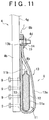
- This contact portion 6 is formed by an inner bag 11 and an outer bag 13 that covers the inner bag 11, and the like, as shown in FIG. 7 .
- the inner bag 11 is a member that is able take on two opposite forms, i.e., one in which the shape of the inner bag 11 is able to flexibly deform and another in which the shape of the inner bag 11 is firmly maintained, with a single member.
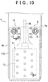
- This inner bag 11 includes a bag member 11a and a connecting port 11b and the like.
- the bag member 11a is a member made of nitrile rubber (NBR) that is elastic and airtight.
- NBR nitrile rubber
- the bag member 11a is formed in a bag shape by folding a generally rectangular sheet made of NBR in half and vulcanize-bonding the mating surfaces of the three peripheral sides except for the side that is folded over.
- a hole portion 11f is formed in generally the center portion of the folded side of the bag member 11a, and the connecting port 11b that serves as a member for communicating the inside of the bag member 11a with the outside of the bag member 11a is arranged in the hole portion 11f.
- the connecting port 11b is attached to the hole portion 11f while ensuring that the hole portion 11f is airtight by inserting seal members 11d and fastening them by screwing on nuts 11c.
- the vacuum duct 8b is connected to the connecting port 11b, and a filter 11e is arranged at an end portion of the connecting port 11b that is inside the bag member 11a.
- the inner bag 11 is configured to prevent the granular substance 12 from coming out of the connecting port 11b by the filter 11e.
- NBR nitrile rubber
- the material of which the inner bag 11 is made is not limited to this. As long as the material is elastic and airtight, any of a variety of materials may be used according to conditions such as the operating environment and the like.
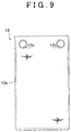
- the outer bag 13 is a member for covering and protecting the inner bag 11, and includes a bag body 13a and anchoring portions 13b and the like.
- the bag body 13a is a member made of aramid fiber that is resistant to abrasion and cutting.
- the bag body 13a is formed in a bag shape by overlapping two generally rectangular sheets of aramid fiber material and sewing them together on three sides.
- the size of the inside of the bag body 13a is large enough to be able to displaceably house the inner bag 11.
- the anchoring portions 13b and the like that serve as portions for hanging the outer bag 13 are attached at an area near the open side where the bag body 13a is not sewn.
- a simple structure that employs metal grommets for the anchoring portions 13b is used.
- aramid fiber is used as the material of the outer bag 13 (i.e., the bag body 13a).
- Aramid fiber is material that has extremely good resistance to abrasion and cutting, so it is able to reliably protect the inner bag 11 against abrasion and cutting.
- aramid fiber is flexible enough to conform to the shape of the workpiece, so the inner bag 11 that is housed in the outer bag 13 is able to accurately conform to the shape of the workpiece that it contacts via the outer bag 13. Therefore, aramid fiber is suitable as material for forming the outer bag 13 (i.e., the bag body 13a).
- aramid fiber of an appropriate form may be used, whether it be woven, knit, or nonwoven, etc.
- woven aramid fiber is preferably used.
- aramid fiber is used as the material of the outer bag 13.
- the material of which the outer bag 13 is made is not limited to this. Any of a variety of materials may be used as long as it has excellent resistance to abrasion and cutting, and is flexible enough to conform to the shape of the workpiece.
- the contact portion 6 is formed with the inner bag 11 housed inside the outer bag 13, as shown in FIG. 7 .
- This configuration makes it possible to simply and reliably inhibit the inner bag 11 from wearing due to repeated use, or from being cut by cutting dust or the like that has adhered to the workpiece. As a result, the product life of the inner bag 11 can be extended.
- the contact portion 6 is such that the inner bag 11 and the outer bag 13 are formed of separate bodies, and the inner bag 11 and the outer bag 13 are able to be displaced relative to each other. As a result, deformation of the inner bag 11 will not be cramped or impeded by the outer bag 13. Therefore, the inner bag 11 is able to accurately conform to the shape of the workpiece via the outer bag 13, so the contact portion 6 is able to accurately conform to the shape (i.e., the concavo-convex portion) of the workpiece.
- the inner bag 11 and the outer bag 13 be separate bodies enables a more firm grasping state to be achieved with the contact portion 6, compared with a contact portion that has a bag body with a double-layered structure in which the inner bag and the outer bag are integrated. Furthermore, with the contact portion 6, it is possible to replace only the inner bag 11 if the inner bag 11 becomes damaged, or replace only the outer bag 13 if the outer bag 13 becomes damaged. As a result, the contact portion 6 is also very economical.
- the contact portion 6 hangs by the anchoring portions 13b of the outer bag 13 from the bolts 4d of the squeezing portions 4b. Then nuts 14 are fastened via washers 15 onto the bolts 4d while the contact portion 6 (i.e., the outer bag 13) is hanging from the anchoring portions 13b, so the contact portion 6 is easily and reliably attached to the squeezing portions 4b. With this kind of structure, the contact portion 6 is easily replaced. Therefore, the contact portion 6 can be easily introduced into an actual production line where abrasion and cutting is anticipated.
- the contact portion 6 that is attached in this way contacts the retaining portion 10 on the surface on the side that contacts the attaching surface 4g.
- the contact portions 6 are attached to the squeezing portions 4b and 5b using the nuts and bolts and the like.
- the invention is not limited by the mode by which the contact portions 6 are attached to the squeezing portions 4b and 5b.
- the contact portions 6 may be attached using resin bands, or the contact portions 6 may be fixed so as to be able to detach easily by one-touch clasps. That is, any of a variety of attaching methods may be used as long as the contact portions 6 are able to be attached to the retaining portions 10, and the contact portions 6 can easily be detached without falling off of the squeezing portions 4b and 5b.
- the granular substance 12 is filled inside the contact portion 6 (i.e., more specifically, the bag member 11a).
- the bag member 11a and the granular substance 12 are hardened in a suitable shape in an integrated state by reducing the pressure inside the bag member 11a such that the grains that form the granular substance 12 are held firmly together.
- the contact portion 6 preferably has properties such as 1) having good hardness when hardened, and 2) being lightweight, but the hardness of the contact portion 6 when hardened and the weight of the contact portion 6 change according to various changes in the specifications of the granular substance 12. Therefore, in this example embodiment, the hardness when hardened with granular substances of various specifications was measured using a test apparatus such as that shown in FIG. 12A , and the granular substance to be filled into the contact portion 6 was selected base on the measurement results.
- a test apparatus 40 includes a case 41 for filling the granular substance, an elastic membrane member 42 that seals an open portion of the case 41, and a push-pull gauge 43 for measuring the hardness when hardened, and the like.
- a plastic container with a volume of approximately 20 x 20 x 15 mm was used as the case 41, and a resin sheet was used as the membrane member 42.
- the push-pull gauge 43 that was used has a pushing portion 43a with a diameter of 6 mm (the pushing area is approximately 28.3 mm 2 ).
- the case 41 was filled with a granular substance, and then an open portion 41a of the case 41 was sealed with the membrane member 42.
- the inside of the case 41 was evacuated such that the granular substance inside the case 41 hardened.
- the push-pull gauge 43 was pushed against the hardened granular substance via the membrane member 42 and the compression force was measured.
- the peak value of the measured compression force at that time was recorded as the hardness index.
- the hardness of the each type of granular substance was evaluated after measuring the peak value for each type of granular substance three times.
- FIG. 12B is a chart of the measurement results after measuring the hardness of each type of granular substance with the test apparatus 40.
- the measurement results for 20 typical types of granular substances, from among those selected, are shown.
- the hardness column shows the minimum to maximum values of the three measurement results.
- the granular substance filled in the contact portion 6 be lightweight, so of the types with the top seven hardness measurement results, the metal powders and the abrasive grain, which are iron or the like and have a large specific gravity, were eliminated as selection candidates. This left the salt and the ceramic fragments (large) as selection candidates.
- the ceramic fragments (large) form a granular substance in which the grains that are formed of artificial ceramic (so-called synthetic mullite) including at least Al 2 O 3 and SiO 2 , that has been crushed such that the average grain diameter is approximately 0.4 to 0.5 mm, inclusive, are shaped with edge portions.
- synthetic mullite artificial ceramic
- These ceramic fragments (large) are suitable for the granular substance in view of their hardness, the stability of the chemical property, and light weight (i.e., small specific gravity).
- the following can be considered from the test results shown in the chart in FIG. 12B .
- the shape of the grains forming each of these granular substances is generally spherical. That is, it is difficult to obtain good hardness of the granular substance that is filled into the contact portion 6 if the shape of the grains that form that granular substance is generally spherical.
- the reason why the contact portion 6 becomes hard when the pressure is reduced is because adjacent grains that are in contact with one another more firmly anchor one another, so grains that are generally spherical with no edge portions or flat surfaces will anchor one another less firmly.
- the term generally spherically here refers to a shape in which there are no edge portions or flat portions, or concavo-convex portions that are able to lock together with other grains or the like, on the outside.
- This term does not necessarily mean completely spherical, but is a concept that also includes shapes such as elliptic spheres and barrel shapes.
- a granular substance to be filled into the contact portion 6 in which the shape of the grains that make up the granular substance is other than generally spherical, and has edge portions and flat portions.
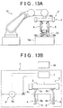
- the grasping portion 2 of the grasping apparatus 1 is arranged on a tip portion 16a of a robotic arm 16.
- the grasping portion 2 grasps the workpiece 50, and the robotic arm 16 transports the workpiece 50.
- the workpiece 50 is placed in a predetermined position on a workpiece placement portion 16c, positioned by positioning portions 16b formed by positioning pins or the like, for example.
- control device 7 of the grasping apparatus 1 is connected to the robotic arm 16, and information such as the placement and angle and the like of the tip portion 16a of the robotic arm 16 is input to the control device 7.
- the robotic arm 16 places the grasping portion 2 in a predetermined position with respect to the workpiece 50 by adjusting the placement and angle and the like of the tip portion 16a. Then, a signal indicating that the grasping portion 2 has been placed in the predetermined position with respect to the workpiece 50 is input to the control device 7 from the robotic arm 16. At this time, the control device 7 places the grasping portion 2 such that the workpiece 50 is arranged between the pawl portions 4 and 5, and concavo-convex portions 50a, 50b, and 50c that are portions of the workpiece 50 that are suitable to be grasped are arranged in positions facing the contact portions 6.
- control device 7 adjusts the distance between the pawl portions 4 and 5 to be equal to or less than the width of the workpiece 50 by adjusting the stroke of the slider portions 3a and 3b, as shown in FIGS. 13B and 14B . Then the pawl portions 4 and 5 grasp the workpiece 50 with a predetermined squeezing pressure.
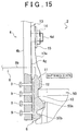
- the contact portions 6 are pressed against the concavo-convex portions 50a and 50b of the workpiece 50 and deform following the shapes of the concavo-convex portions 50a and 50b. Also at this time, the contact portions 6 are also pressed on the attaching surface 4g side, and thus also deform following the shape of the retaining portions 10 (i.e., the tip end portions of the bolts 9) formed on the attaching surfaces 4g.
- each contact portion 6 is such that the inner bag 11 is housed inside the outer bag 13 made of aramid fiber, and the inner bag 11 and the outer bag 13 are able to deform relative to one another. Therefore, the outer bag 13 will not impede the deformation of the inner bag 11. As a result, with the grasping portion 2, the contact portions 6 are able to reliably conform to the shapes of retaining portions 10 and the concavo-convex portions 50a, 50b, and 50c of the workpiece 50.
- a command signal is output from the control device 7 to the vacuum pump 8a to evacuate the inside of the inner bags 11 of the contact portions 6, as shown in FIGS. 13B and 16A .
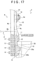
- the contact portions 6 harden in a state conformed to the shape of the concavo-convex portions 50a and 50b of the workpiece 50. Also at this time, the contact portions 6 harden in a state conforming to the shape of the retaining portion 10.
- the retaining portions 10 are able to adjust the retaining force (i.e., the friction force) with respect to the contact portions 6 by adjusting the amount that the bolts 9 protrude from the attaching surfaces 4g.
- the contact portions 6 the granular substance 12, i.e., the ceramic fragments (i.e., the ceramic fragments (large) (No. 18) in FIG. 12B ), is filled into the inner bags 11, so shapes conforming to the retaining portions 10 and the concavo-convex portions 50a and 50b, and 50c of the workpiece 50 are able to be reliably maintained at a sufficient hardness. Therefore, the contact portions 6 will not be displaced with respect to the workpiece 50, and are retained by the retaining portions 10 and thus will not be displaced with respect to the squeezing portions 4b either, so a firm grasping state can be created by the grasping portion 2. As a result, when transporting the workpiece 50, the workpiece 50 can be reliably inhibited from being displaced with respect to the pawl portions 4 and 5, so the workpiece 50 can be transported while ensuring positioning accuracy.
- the ceramic fragments i.e., the ceramic fragments (large) (No. 18) in FIG. 12B
- the contact portions 6 become displaced with respect to the workpiece 50 or the squeezing portions 4b, the workpiece 50 that has been positioned by the positioning pins (i.e., positioning pins 16b) may be damaged by the positioning pins when the workpiece 50 is grasped and lifted up.
- the grasping portion 2 is able to grasp the workpiece 50 while accurately maintaining the positional relationship between the workpiece 50 and the pawl portions 4 and 5, so the workpiece 50 will not be damaged by the positioning pins, and the positioning accuracy after transport can be precisely ensured.
- the grasping apparatus 1 includes the grasping portion 2 for grasping the workpiece 50.
- the grasping portion 2 includes the pawl portions 4 and 5 that have the plurality of squeezing portion 4b and 5b that squeeze the workpiece 50, and the contact portions 6.
- Each of the contact portions 6 includes the inner bag 11 that is a bag member made of elastic material, and the granular substance 12 that is filled into the inner bag 11.
- the contact portions 6 are attached to portions of the squeezing portions 4b and 5b that contact the workpiece 50.
- the contact portions 6 harden the granular substance 12 while keeping it in an appropriate shape (e.g., conforming to the concavo-convex portions 50a, 50b, and 50c of the workpiece 50), by reducing the pressure inside the inner bags 11 to increase the volume ratio of the granular substance 12 to the inner volume of the inner bags 11.
- the retaining portions 10 that have concavo-convex shapes are formed on the attaching surfaces 4g that are portions of the squeezing portions 4b and 5b that the contact portions 6 attach to. According to this kind of structure, the contact portions 6 are inhibited from being displaced with respect to the squeezing portions 4b and 5b when the grasping portion 2 grasps the workpiece 50.
- each of the contact portions 6 has the outer bag 13 that covers the inner bag 11 and is made of aramid fiber. This kind of structure makes it possible to inhibit the contact portions 6 from being displaced with respect to the squeezing portions 4b and 5b while ensuring the resistance to abrasion and cutting of the contact portions 6.
- the inner bag 11 is housed inside the outer bag 13 in a state relatively displaceable with respect to the outer bag 13.
- This kind of structure enables the inner bag 11 to accurately conform to the shape of the retaining portion 10, and thus makes it possible to more reliably inhibit the contact portions 6 from being displaced with respect to the squeezing portions 4b and 5b.
- the granular substance 12 is formed by ceramic fragments (i.e., the ceramic fragments (large) (No. 18) in FIG. 12B ) in which the shape of the grains that make up the granular substance 12 is a shape other than generally spherical.
- This kind of structure enables the contact portions 6 to be even harder when hardened, and thus makes it possible to more reliably inhibit the contact portions 6 from being displaced with respect to the squeezing portions 4b and 5b.
- control device 7 adjusts the distance between the pawl portions 4 and 5 so that it is greater than the width of the workpiece 50 by adjusting the stroke of the slider portions 3a and 3b, as shown in FIG. 16B . Then, the workpiece 50 is released from being grasped by the pawl portions 4 and 5.
- the control device 7 When handling a workpiece having a shape different than that of the workpiece 50, the control device 7 outputs a command signal to the electromagnetic valve 8c to open the electromagnetic valve 8c, thus breaking the vacuum state in the contact portions 6 so that the contact portions 6 can return to their normal state.
- the grasping apparatus 1 that has a single grasping portion 2. Therefore, the trouble and the like related to changing the contact portions 6 so that they correspond to the shape of the workpiece each time the type of workpiece changes is eliminated, so productivity can be improved.
- command signals are output from the control device 7 to the vacuum pump 8a and the electromagnetic valve 8c to stop the vacuum pump 8a and close the electromagnetic valve 8c.
- the reduced-pressure state inside the bag member 11a is maintained, enabling the contact portions 6 to easily be kept in the hardened state.
- the contact portions 6 can be kept in the hardened state in a form suitable for grasping the workpiece 50 as long as the reduced-pressure state in the bag member 11a is maintained. Accordingly, when transporting a plurality of the workpieces 50 in succession, the workpieces 50 can be reliably grasped and transported while ensuring positioning accuracy, by the contact portions 6 that are in a form suitable for grasping the workpiece 50.
- the grasping apparatus 1 is applied to a transport apparatus, but the use of the grasping apparatus 1 is not limited to this.
- the grasping apparatus 1 may also be used as a tool for temporarily fixing a workpiece during the assembly of a product, or as a tool for stably holding a workpiece having an unstable shape for storage or the like.
Landscapes
- Engineering & Computer Science (AREA)
- Mechanical Engineering (AREA)
- Robotics (AREA)
- Manipulator (AREA)
- Basic Packing Technique (AREA)
Claims (6)
- Appareil de préhension comprenant :une partie de préhension pour saisir une pièce (50), la partie de préhension comprenant i) des parties de cliquet (4, 5) ayant une pluralité de parties de compression (4b, 5b) qui compriment la pièce, et ii) des parties de contact (6) dont chacune a un élément de type sac (11) réalisé à partir d'un matériau élastique, et une substance granulaire (12) qui est versée dans l'élément de type sac, les parties de contact (6) étant fixées aux parties des parties de compression (4b, 5b) et agencées, à l'usage, pour être en contact avec la pièce, et durcir la substance granulaire tout en mettant la substance granulaire dans une forme appropriée en augmentant un rapport de volume de la substance granulaire sur un volume interne de l'élément de type sac, caractérisé en ce qui :une partie de retenue (10) qui a une forme concavo-convexe est formée au niveau d'une partie de chacune des parties de cliquet (4, 5) auxquelles la partie de contact (6) correspondante est fixée ; eten ce que, lorsque les parties de cliquet compriment la pièce, les parties de contact sont comprimées contre la pièce, et la substance granulaire est durcie dans un état dans lequel les parties de contact sont déformées selon la forme de la pièce et la forme des parties de retenue, durcissant ainsi les parties de contact dans un état conformé à la forme de la pièce et à la forme des parties de retenue afin de saisir la pièce.
- Appareil de préhension selon la revendication 1, dans lequel chacune des parties de contact comprend un sac externe (13) qui est réalisé avec des fibres d'aramide et qui recouvre l'élément de type sac.
- Appareil de préhension selon la revendication 2, dans lequel l'élément de type sac est logé à l'intérieur du sac externe dans un état relativement déplaçable par rapport au sac externe.
- Appareil de préhension selon l'une quelconque des revendications 1 à 3, dans lequel la substance granulaire est des fragments de céramique, dans laquelle une forme de chacun des grains qui composent la substance granulaire, est une forme différente d'une forme généralement sphérique.
- Appareil de préhension selon la revendication 4, dans lequel les grains de la substance granulaire qui sont formés avec de la céramique artificielle comprenant au moins Al2O3 et SiO2 qui a été écrasée de sorte qu'un diamètre de grain moyen mesure approximativement de 0,4 à 0,5 mm y compris, sont formés avec des parties de bord.
- Appareil de préhension selon l'une quelconque des revendications 1 à 5, comprenant des moyens d'évacuation (8) raccordés à chaque élément de type sac, dans lequel les moyens d'évacuation peuvent fonctionner pour réduire la pression dans l'élément de type sac.
Applications Claiming Priority (2)
| Application Number | Priority Date | Filing Date | Title |
|---|---|---|---|
| JP2010104329A JP5130320B2 (ja) | 2010-04-28 | 2010-04-28 | 把持装置 |
| PCT/IB2011/001139 WO2011135450A1 (fr) | 2010-04-28 | 2011-04-19 | Appareil de préhension à éléments de type poches remplies par une substance granulaire |
Publications (2)
| Publication Number | Publication Date |
|---|---|
| EP2563555A1 EP2563555A1 (fr) | 2013-03-06 |
| EP2563555B1 true EP2563555B1 (fr) | 2016-08-10 |
Family
ID=44592151
Family Applications (1)
| Application Number | Title | Priority Date | Filing Date |
|---|---|---|---|
| EP11726495.2A Active EP2563555B1 (fr) | 2010-04-28 | 2011-04-19 | Appareil de prehension a elements de type poches remplies par une substance granulaire |
Country Status (7)
| Country | Link |
|---|---|
| US (1) | US8651543B2 (fr) |
| EP (1) | EP2563555B1 (fr) |
| JP (1) | JP5130320B2 (fr) |
| CN (1) | CN102858502B (fr) |
| BR (1) | BR112012027305B1 (fr) |
| PL (1) | PL2563555T3 (fr) |
| WO (1) | WO2011135450A1 (fr) |
Families Citing this family (84)
| Publication number | Priority date | Publication date | Assignee | Title |
|---|---|---|---|---|
| DE112011101331T5 (de) | 2010-04-15 | 2013-01-31 | Cornell University | Greif- und Ablegevorrichtung und -verfahren |
| JP2012152860A (ja) * | 2011-01-26 | 2012-08-16 | Toyota Motor Corp | 把持装置およびその制御方法 |
| JP5765248B2 (ja) * | 2012-01-16 | 2015-08-19 | トヨタ自動車株式会社 | 当接部の製造方法 |
| JP5929271B2 (ja) * | 2012-02-07 | 2016-06-01 | セイコーエプソン株式会社 | ロボットハンドおよびロボット |
| US9616580B2 (en) | 2012-05-14 | 2017-04-11 | Sarcos Lc | End effector for a robotic arm |
| JP5846057B2 (ja) | 2012-06-29 | 2016-01-20 | トヨタ自動車株式会社 | 把持装置による把持方法 |
| JP6010408B2 (ja) * | 2012-09-24 | 2016-10-19 | 帝人エンジニアリング株式会社 | 高温物把持装置 |
| US9579219B2 (en) | 2012-10-25 | 2017-02-28 | Cornell University | Robotic apparatus, method, and applications |
| JP6032054B2 (ja) | 2013-02-20 | 2016-11-24 | トヨタ自動車株式会社 | 把持装置の当接部材 |
| US9463541B2 (en) * | 2013-03-08 | 2016-10-11 | Bell Helicopter Textron Inc. | Selectively compliant clamp |
| WO2015006613A1 (fr) * | 2013-07-10 | 2015-01-15 | Empire Robotics, Inc. | Effecteur terminal, appareil, système et procédé pour saisir et relâcher des articles et analogues |
| KR20160096075A (ko) * | 2013-12-10 | 2016-08-12 | 엔오케이 가부시키가이샤 | 피복재 및 로봇 파지부의 피복 구조 |
| JP6191432B2 (ja) * | 2013-12-10 | 2017-09-06 | Nok株式会社 | 被覆材及びロボット把持部の被覆構造 |
| JP6340930B2 (ja) * | 2014-06-13 | 2018-06-13 | Nok株式会社 | 被覆材及びロボット把持部の被覆構造 |
| WO2015123128A1 (fr) * | 2014-02-11 | 2015-08-20 | Empire Robotics, Inc. | Dispositifs de préhension de blocage et procédés d'utilisation |
| US10406676B2 (en) | 2014-05-06 | 2019-09-10 | Sarcos Lc | Energy recovering legged robotic device |
| US10766133B2 (en) | 2014-05-06 | 2020-09-08 | Sarcos Lc | Legged robotic device utilizing modifiable linkage mechanism |
| CN104908049A (zh) * | 2014-06-06 | 2015-09-16 | 苏州晓炎自动化设备有限公司 | 一种球形机器手 |
| JP6179729B2 (ja) * | 2014-06-13 | 2017-08-16 | 株式会社ダイフク | コンテナ昇降搬送装置 |
| US9457477B1 (en) * | 2014-08-25 | 2016-10-04 | Google Inc. | Variable stiffness suction gripper |
| JP6114248B2 (ja) * | 2014-11-14 | 2017-04-12 | 帝人エンジニアリング株式会社 | パレットおよび搬送システム |
| CN107708939A (zh) * | 2015-03-23 | 2018-02-16 | 软机器人公司 | 对软机器人致动器的改进及其制造方法 |
| WO2016201418A1 (fr) * | 2015-06-11 | 2016-12-15 | Soft Robotics, Inc. | Systèmes robotiques modulaires |
| JP6418397B2 (ja) * | 2015-08-24 | 2018-11-07 | 株式会社ダイフク | 物品搬送用容器の昇降搬送装置 |
| WO2017106263A1 (fr) * | 2015-12-16 | 2017-06-22 | Comau Llc | Effecteur terminal adaptable et procédé |
| EP3252317B1 (fr) | 2016-06-01 | 2020-01-29 | Piab Ab | Commande d'un système à vide comprenant un ensemble de générateur de vide |
| US10449754B2 (en) * | 2016-06-28 | 2019-10-22 | The Boeing Company | Wrinkle reduction in formed composite laminates |
| CN106003133A (zh) * | 2016-07-28 | 2016-10-12 | 成都普崔克机电有限公司 | 一种用于机械手的自适应软垫 |
| US10765537B2 (en) | 2016-11-11 | 2020-09-08 | Sarcos Corp. | Tunable actuator joint modules having energy recovering quasi-passive elastic actuators for use within a robotic system |
| US10821614B2 (en) | 2016-11-11 | 2020-11-03 | Sarcos Corp. | Clutched joint modules having a quasi-passive elastic actuator for a robotic assembly |
| US10828767B2 (en) | 2016-11-11 | 2020-11-10 | Sarcos Corp. | Tunable actuator joint modules having energy recovering quasi-passive elastic actuators with internal valve arrangements |
| US10919161B2 (en) | 2016-11-11 | 2021-02-16 | Sarcos Corp. | Clutched joint modules for a robotic system |
| CN106426187B (zh) * | 2016-12-24 | 2019-04-19 | 聊城鑫泰机床有限公司 | 工业机器人控制方法 |
| CN106426188B (zh) * | 2016-12-24 | 2018-10-30 | 江苏山扬智能装备有限公司 | 一种程控工业机器人 |
| CN109129489B (zh) * | 2017-01-07 | 2021-11-26 | 汇韩科技(常州)有限公司 | 程控工业搬运机器人以及控制方法 |
| US10343290B2 (en) * | 2017-03-08 | 2019-07-09 | Amazon Technologies, Inc. | Conformable variable friction manipulator |
| JP6470331B2 (ja) * | 2017-03-13 | 2019-02-13 | 株式会社東芝 | 把持ツール、把持システム、および把持性能の評価方法 |
| JP6588935B2 (ja) * | 2017-03-13 | 2019-10-09 | 株式会社東芝 | 把持ツール、把持システム、および把持性能の評価方法 |
| JP6514254B2 (ja) | 2017-03-13 | 2019-05-15 | 株式会社東芝 | 把持ツールおよび把持システム |
| JP6931292B2 (ja) * | 2017-03-23 | 2021-09-01 | 三井化学株式会社 | グリッパーおよび把持方法 |
| US20180282086A1 (en) * | 2017-04-03 | 2018-10-04 | Xerox Corporation | Universal part gripper with conformable tube grippers |
| JP7117565B2 (ja) * | 2017-07-28 | 2022-08-15 | パナソニックIpマネジメント株式会社 | ロボットハンド装置、ロボットハンドシステム及び保持方法 |
| ES2962547T3 (es) * | 2017-08-14 | 2024-03-19 | Contactile Pty Ltd | Sistema y procedimiento para evaluar seguridad de agarre |
| JP6588949B2 (ja) | 2017-09-26 | 2019-10-09 | 株式会社東芝 | 把持ツール、把持システム、および樹脂部材の製造方法 |
| CN108058184B (zh) * | 2017-11-09 | 2020-09-29 | 大连理工大学 | 一种用于夹钳换接的电磁吸附式换接装置 |
| US10843330B2 (en) | 2017-12-07 | 2020-11-24 | Sarcos Corp. | Resistance-based joint constraint for a master robotic system |
| US11331809B2 (en) | 2017-12-18 | 2022-05-17 | Sarcos Corp. | Dynamically controlled robotic stiffening element |
| CN108100658B (zh) * | 2018-01-31 | 2024-03-29 | 宁夏巨能机器人股份有限公司 | 一种用于翻转清洗装置的抓取机构 |
| JP7006404B2 (ja) * | 2018-03-15 | 2022-01-24 | トヨタ自動車株式会社 | ワークの支持装置、支持方法及びロボットアーム |
| KR102093979B1 (ko) * | 2018-06-22 | 2020-03-27 | 주식회사 다우에프에이 | 형상적응형 그리퍼 |
| JP6969510B2 (ja) * | 2018-06-29 | 2021-11-24 | トヨタ車体株式会社 | ワーク把持装置 |
| JP7403130B2 (ja) * | 2018-08-08 | 2023-12-22 | ユニプレス株式会社 | 把持装置、及びロボット装置 |
| CN108994865A (zh) * | 2018-09-03 | 2018-12-14 | 苏州迪天机器人自动化有限公司 | 一种抓取装置 |
| JP6841804B2 (ja) * | 2018-09-28 | 2021-03-10 | ファナック株式会社 | ロボットハンド |
| JP7127513B2 (ja) * | 2018-11-30 | 2022-08-30 | トヨタ自動車株式会社 | センサシステムおよびロボットハンド |
| US11241801B2 (en) | 2018-12-31 | 2022-02-08 | Sarcos Corp. | Robotic end effector with dorsally supported actuation mechanism |
| US10906191B2 (en) | 2018-12-31 | 2021-02-02 | Sarcos Corp. | Hybrid robotic end effector |
| US11351675B2 (en) * | 2018-12-31 | 2022-06-07 | Sarcos Corp. | Robotic end-effector having dynamic stiffening elements for conforming object interaction |
| JP7151598B2 (ja) * | 2019-04-04 | 2022-10-12 | 株式会社ダイフク | 物品保持装置 |
| JP7159951B2 (ja) * | 2019-04-04 | 2022-10-25 | 株式会社ダイフク | 物品把持装置 |
| KR102182345B1 (ko) * | 2019-05-03 | 2020-11-24 | 재단법인대구경북과학기술원 | 그리퍼 시스템 |
| US11007654B2 (en) * | 2019-06-21 | 2021-05-18 | Intelligrated Headquarters, Llc | End manipulator for package picking and placing |
| CN110654976B (zh) * | 2019-09-10 | 2020-10-30 | 东阳市智享机械科技有限公司 | 一种双水平面不同的混凝土防划损支承块吊具 |
| CN113924194B (zh) | 2019-11-11 | 2024-12-17 | 耐克塞拉机器人公司 | 用于可适应抽吸装置的方法和设备 |
| JP7230779B2 (ja) * | 2019-11-12 | 2023-03-01 | トヨタ自動車株式会社 | ロボットハンドの使用方法 |
| US12275140B2 (en) | 2019-11-29 | 2025-04-15 | Commonwealth Scientific And Industrial Research Organisation | Robotic manipulator |
| CN112091996B (zh) * | 2020-08-31 | 2023-04-18 | 上海大学 | 一种基于颗粒塑形的仿生机器人夹持器 |
| US11833676B2 (en) | 2020-12-07 | 2023-12-05 | Sarcos Corp. | Combining sensor output data to prevent unsafe operation of an exoskeleton |
| IT202100000497A1 (it) * | 2021-01-13 | 2022-07-13 | Gmm S P A | Apparato e metodo per movimentare coppie di pezzi lavorati aventi una faccia grezza e una opposta faccia rifinita |
| CN112454405B (zh) * | 2021-01-26 | 2021-04-13 | 广东顺力智能物流装备股份有限公司 | 一种智能化物料搬运机械手 |
| CN112959350B (zh) * | 2021-02-05 | 2022-08-09 | 平顶山市博翔碳素有限公司 | 一种液压两爪加工工装 |
| CN113478510B (zh) * | 2021-06-30 | 2022-12-02 | 江西机电职业技术学院 | 一种机械抓手 |
| US12162139B1 (en) * | 2021-10-25 | 2024-12-10 | Amazon Technologies, Inc. | Gripping tool with expandable, compliant grippers, and related systems and methods |
| CN114014150B (zh) * | 2021-11-17 | 2024-04-02 | 中铁一局集团有限公司 | 一种用于管片垂直吊装的吊带防滑脱装置 |
| DE102021132810B4 (de) | 2021-12-13 | 2025-12-11 | Zimmer Gmbh | Klemmgreifer |
| JP7653932B2 (ja) * | 2022-01-26 | 2025-03-31 | タイガースポリマー株式会社 | グリッパ |
| US11826907B1 (en) | 2022-08-17 | 2023-11-28 | Sarcos Corp. | Robotic joint system with length adapter |
| US11717956B1 (en) | 2022-08-29 | 2023-08-08 | Sarcos Corp. | Robotic joint system with integrated safety |
| CN119998086A (zh) * | 2022-10-12 | 2025-05-13 | 南洋理工大学 | 抓拾构件及抓拾系统 |
| US12172298B2 (en) | 2022-11-04 | 2024-12-24 | Sarcos Corp. | Robotic end-effector having dynamic stiffening elements with resilient spacers for conforming object interaction |
| US11897132B1 (en) | 2022-11-17 | 2024-02-13 | Sarcos Corp. | Systems and methods for redundant network communication in a robot |
| US11924023B1 (en) | 2022-11-17 | 2024-03-05 | Sarcos Corp. | Systems and methods for redundant network communication in a robot |
| US12377557B2 (en) * | 2023-01-14 | 2025-08-05 | Sarcos Corp. | Robotic article handling end effector with capture device having a compliant material |
| CN117381691B (zh) * | 2023-11-16 | 2025-12-30 | 无锡锡州机械有限公司 | 一种适合薄壁圆柱体加工的夹具 |
Family Cites Families (16)
| Publication number | Priority date | Publication date | Assignee | Title |
|---|---|---|---|---|
| US3318629A (en) * | 1965-04-09 | 1967-05-09 | Jr Richard W Brandt | Tree-clamping jaws with deformable pads containing granular material |
| JPS5250536Y2 (fr) * | 1972-10-26 | 1977-11-16 | ||
| DE2840188C3 (de) * | 1978-09-15 | 1981-11-12 | Fraunhofer-Gesellschaft zur Förderung der angewandten Forschung e.V., 8000 München | Greiferbacke für Greifer von Handhabungssystemen |
| JPS56114688A (en) | 1980-02-07 | 1981-09-09 | Sintokogio Ltd | Method of holding body |
| FR2492911A1 (fr) * | 1980-10-24 | 1982-04-30 | Petroles Cie Francaise | Pince douce de retenue a element gonflable |
| JPH046847Y2 (fr) * | 1986-09-30 | 1992-02-25 | ||
| JPS6437736A (en) | 1987-08-04 | 1989-02-08 | Seiko Epson Corp | Semiconductor laser driving device |
| JP2699520B2 (ja) * | 1989-02-17 | 1998-01-19 | 日産自動車株式会社 | ロボット |
| JPH06206622A (ja) * | 1993-01-11 | 1994-07-26 | Inax Corp | 移載装置及び移載方法 |
| JPH09123082A (ja) | 1995-11-01 | 1997-05-13 | Kao Corp | 物品把持装置 |
| WO2001072479A1 (fr) * | 2000-03-28 | 2001-10-04 | Seiko Epson Corporation | Actionneur flexible integre a une pompe |
| JP3756178B2 (ja) * | 2003-06-27 | 2006-03-15 | 松下電器産業株式会社 | 積層型多関節部駆動機構及びその製造方法、それを備えた把持ハンド、ロボットアーム、ロボット |
| WO2006082100A1 (fr) | 2005-02-05 | 2006-08-10 | Andreas Plaas-Link | Dispositif universel de saisie et de retenue |
| JP4648159B2 (ja) * | 2005-11-10 | 2011-03-09 | 本田技研工業株式会社 | 把持装置 |
| JP4648158B2 (ja) * | 2005-11-10 | 2011-03-09 | 本田技研工業株式会社 | ワーク位置決め方法及びその装置 |
| FR2917660B1 (fr) * | 2007-06-25 | 2009-09-25 | Commissariat Energie Atomique | Pince pour robot manipulateur a precision de serrage amelioree et robot manipulateur comportant au moins une telle pince. |
-
2010
- 2010-04-28 JP JP2010104329A patent/JP5130320B2/ja active Active
-
2011
- 2011-04-19 EP EP11726495.2A patent/EP2563555B1/fr active Active
- 2011-04-19 WO PCT/IB2011/001139 patent/WO2011135450A1/fr not_active Ceased
- 2011-04-19 US US13/641,534 patent/US8651543B2/en active Active
- 2011-04-19 PL PL11726495T patent/PL2563555T3/pl unknown
- 2011-04-19 BR BR112012027305-1A patent/BR112012027305B1/pt not_active IP Right Cessation
- 2011-04-19 CN CN201180019586.0A patent/CN102858502B/zh active Active
Also Published As
| Publication number | Publication date |
|---|---|
| BR112012027305A2 (pt) | 2017-10-24 |
| US20130033050A1 (en) | 2013-02-07 |
| PL2563555T3 (pl) | 2017-02-28 |
| BR112012027305B1 (pt) | 2021-04-27 |
| WO2011135450A1 (fr) | 2011-11-03 |
| JP2011230260A (ja) | 2011-11-17 |
| EP2563555A1 (fr) | 2013-03-06 |
| US8651543B2 (en) | 2014-02-18 |
| CN102858502A (zh) | 2013-01-02 |
| CN102858502B (zh) | 2014-12-17 |
| JP5130320B2 (ja) | 2013-01-30 |
Similar Documents
| Publication | Publication Date | Title |
|---|---|---|
| EP2563555B1 (fr) | Appareil de prehension a elements de type poches remplies par une substance granulaire | |
| EP2866981B1 (fr) | Procédé de préhension par un appareil de préhension | |
| US7845698B2 (en) | Gripper with adjustable bumper stops | |
| US11298833B2 (en) | Gripper, grasping device, and industrial robot | |
| EP3527337B1 (fr) | Dispositif de préhension et robot industriel | |
| JP6010408B2 (ja) | 高温物把持装置 | |
| EP3689558B1 (fr) | Dispositif de préhension et robot industriel | |
| CN104995002A (zh) | 把持装置 | |
| JP5434779B2 (ja) | 把持装置 | |
| WO2019167652A1 (fr) | Dispositif de préhension et robot industriel | |
| US20250332741A1 (en) | Gripping apparatus having a compressing unit | |
| EP4606532A1 (fr) | Dispositif de préhension pour un dispositif robotique | |
| WO2018092914A1 (fr) | Dispositif de préhension et robot industriel |
Legal Events
| Date | Code | Title | Description |
|---|---|---|---|
| PUAI | Public reference made under article 153(3) epc to a published international application that has entered the european phase |
Free format text: ORIGINAL CODE: 0009012 |
|
| 17P | Request for examination filed |
Effective date: 20121026 |
|
| AK | Designated contracting states |
Kind code of ref document: A1 Designated state(s): AL AT BE BG CH CY CZ DE DK EE ES FI FR GB GR HR HU IE IS IT LI LT LU LV MC MK MT NL NO PL PT RO RS SE SI SK SM TR |
|
| DAX | Request for extension of the european patent (deleted) | ||
| GRAP | Despatch of communication of intention to grant a patent |
Free format text: ORIGINAL CODE: EPIDOSNIGR1 |
|
| RIC1 | Information provided on ipc code assigned before grant |
Ipc: B25J 15/00 20060101AFI20160127BHEP Ipc: B66C 1/42 20060101ALI20160127BHEP Ipc: B25J 15/12 20060101ALI20160127BHEP Ipc: B65G 47/90 20060101ALI20160127BHEP |
|
| INTG | Intention to grant announced |
Effective date: 20160226 |
|
| GRAS | Grant fee paid |
Free format text: ORIGINAL CODE: EPIDOSNIGR3 |
|
| GRAA | (expected) grant |
Free format text: ORIGINAL CODE: 0009210 |
|
| AK | Designated contracting states |
Kind code of ref document: B1 Designated state(s): AL AT BE BG CH CY CZ DE DK EE ES FI FR GB GR HR HU IE IS IT LI LT LU LV MC MK MT NL NO PL PT RO RS SE SI SK SM TR |
|
| REG | Reference to a national code |
Ref country code: GB Ref legal event code: FG4D |
|
| REG | Reference to a national code |
Ref country code: CH Ref legal event code: EP Ref country code: AT Ref legal event code: REF Ref document number: 818550 Country of ref document: AT Kind code of ref document: T Effective date: 20160815 |
|
| REG | Reference to a national code |
Ref country code: IE Ref legal event code: FG4D |
|
| REG | Reference to a national code |
Ref country code: DE Ref legal event code: R096 Ref document number: 602011029014 Country of ref document: DE |
|
| REG | Reference to a national code |
Ref country code: LT Ref legal event code: MG4D |
|
| REG | Reference to a national code |
Ref country code: NL Ref legal event code: MP Effective date: 20160810 |
|
| REG | Reference to a national code |
Ref country code: AT Ref legal event code: MK05 Ref document number: 818550 Country of ref document: AT Kind code of ref document: T Effective date: 20160810 |
|
| REG | Reference to a national code |
Ref country code: DE Ref legal event code: R084 Ref document number: 602011029014 Country of ref document: DE |
|
| PG25 | Lapsed in a contracting state [announced via postgrant information from national office to epo] |
Ref country code: RS Free format text: LAPSE BECAUSE OF FAILURE TO SUBMIT A TRANSLATION OF THE DESCRIPTION OR TO PAY THE FEE WITHIN THE PRESCRIBED TIME-LIMIT Effective date: 20160810 Ref country code: IS Free format text: LAPSE BECAUSE OF FAILURE TO SUBMIT A TRANSLATION OF THE DESCRIPTION OR TO PAY THE FEE WITHIN THE PRESCRIBED TIME-LIMIT Effective date: 20161210 Ref country code: FI Free format text: LAPSE BECAUSE OF FAILURE TO SUBMIT A TRANSLATION OF THE DESCRIPTION OR TO PAY THE FEE WITHIN THE PRESCRIBED TIME-LIMIT Effective date: 20160810 Ref country code: NL Free format text: LAPSE BECAUSE OF FAILURE TO SUBMIT A TRANSLATION OF THE DESCRIPTION OR TO PAY THE FEE WITHIN THE PRESCRIBED TIME-LIMIT Effective date: 20160810 Ref country code: LT Free format text: LAPSE BECAUSE OF FAILURE TO SUBMIT A TRANSLATION OF THE DESCRIPTION OR TO PAY THE FEE WITHIN THE PRESCRIBED TIME-LIMIT Effective date: 20160810 Ref country code: HR Free format text: LAPSE BECAUSE OF FAILURE TO SUBMIT A TRANSLATION OF THE DESCRIPTION OR TO PAY THE FEE WITHIN THE PRESCRIBED TIME-LIMIT Effective date: 20160810 Ref country code: NO Free format text: LAPSE BECAUSE OF FAILURE TO SUBMIT A TRANSLATION OF THE DESCRIPTION OR TO PAY THE FEE WITHIN THE PRESCRIBED TIME-LIMIT Effective date: 20161110 Ref country code: IT Free format text: LAPSE BECAUSE OF FAILURE TO SUBMIT A TRANSLATION OF THE DESCRIPTION OR TO PAY THE FEE WITHIN THE PRESCRIBED TIME-LIMIT Effective date: 20160810 |
|
| REG | Reference to a national code |
Ref country code: GB Ref legal event code: 746 Effective date: 20170119 |
|
| PG25 | Lapsed in a contracting state [announced via postgrant information from national office to epo] |
Ref country code: PT Free format text: LAPSE BECAUSE OF FAILURE TO SUBMIT A TRANSLATION OF THE DESCRIPTION OR TO PAY THE FEE WITHIN THE PRESCRIBED TIME-LIMIT Effective date: 20161212 Ref country code: AT Free format text: LAPSE BECAUSE OF FAILURE TO SUBMIT A TRANSLATION OF THE DESCRIPTION OR TO PAY THE FEE WITHIN THE PRESCRIBED TIME-LIMIT Effective date: 20160810 Ref country code: GR Free format text: LAPSE BECAUSE OF FAILURE TO SUBMIT A TRANSLATION OF THE DESCRIPTION OR TO PAY THE FEE WITHIN THE PRESCRIBED TIME-LIMIT Effective date: 20161111 Ref country code: ES Free format text: LAPSE BECAUSE OF FAILURE TO SUBMIT A TRANSLATION OF THE DESCRIPTION OR TO PAY THE FEE WITHIN THE PRESCRIBED TIME-LIMIT Effective date: 20160810 Ref country code: LV Free format text: LAPSE BECAUSE OF FAILURE TO SUBMIT A TRANSLATION OF THE DESCRIPTION OR TO PAY THE FEE WITHIN THE PRESCRIBED TIME-LIMIT Effective date: 20160810 Ref country code: SE Free format text: LAPSE BECAUSE OF FAILURE TO SUBMIT A TRANSLATION OF THE DESCRIPTION OR TO PAY THE FEE WITHIN THE PRESCRIBED TIME-LIMIT Effective date: 20160810 |
|
| REG | Reference to a national code |
Ref country code: FR Ref legal event code: PLFP Year of fee payment: 7 |
|
| PG25 | Lapsed in a contracting state [announced via postgrant information from national office to epo] |
Ref country code: RO Free format text: LAPSE BECAUSE OF FAILURE TO SUBMIT A TRANSLATION OF THE DESCRIPTION OR TO PAY THE FEE WITHIN THE PRESCRIBED TIME-LIMIT Effective date: 20160810 Ref country code: EE Free format text: LAPSE BECAUSE OF FAILURE TO SUBMIT A TRANSLATION OF THE DESCRIPTION OR TO PAY THE FEE WITHIN THE PRESCRIBED TIME-LIMIT Effective date: 20160810 |
|
| REG | Reference to a national code |
Ref country code: DE Ref legal event code: R097 Ref document number: 602011029014 Country of ref document: DE |
|
| PG25 | Lapsed in a contracting state [announced via postgrant information from national office to epo] |
Ref country code: BE Free format text: LAPSE BECAUSE OF FAILURE TO SUBMIT A TRANSLATION OF THE DESCRIPTION OR TO PAY THE FEE WITHIN THE PRESCRIBED TIME-LIMIT Effective date: 20160810 Ref country code: BG Free format text: LAPSE BECAUSE OF FAILURE TO SUBMIT A TRANSLATION OF THE DESCRIPTION OR TO PAY THE FEE WITHIN THE PRESCRIBED TIME-LIMIT Effective date: 20161110 Ref country code: SM Free format text: LAPSE BECAUSE OF FAILURE TO SUBMIT A TRANSLATION OF THE DESCRIPTION OR TO PAY THE FEE WITHIN THE PRESCRIBED TIME-LIMIT Effective date: 20160810 Ref country code: CZ Free format text: LAPSE BECAUSE OF FAILURE TO SUBMIT A TRANSLATION OF THE DESCRIPTION OR TO PAY THE FEE WITHIN THE PRESCRIBED TIME-LIMIT Effective date: 20160810 Ref country code: DK Free format text: LAPSE BECAUSE OF FAILURE TO SUBMIT A TRANSLATION OF THE DESCRIPTION OR TO PAY THE FEE WITHIN THE PRESCRIBED TIME-LIMIT Effective date: 20160810 Ref country code: SK Free format text: LAPSE BECAUSE OF FAILURE TO SUBMIT A TRANSLATION OF THE DESCRIPTION OR TO PAY THE FEE WITHIN THE PRESCRIBED TIME-LIMIT Effective date: 20160810 |
|
| PLBE | No opposition filed within time limit |
Free format text: ORIGINAL CODE: 0009261 |
|
| STAA | Information on the status of an ep patent application or granted ep patent |
Free format text: STATUS: NO OPPOSITION FILED WITHIN TIME LIMIT |
|
| 26N | No opposition filed |
Effective date: 20170511 |
|
| PG25 | Lapsed in a contracting state [announced via postgrant information from national office to epo] |
Ref country code: SI Free format text: LAPSE BECAUSE OF FAILURE TO SUBMIT A TRANSLATION OF THE DESCRIPTION OR TO PAY THE FEE WITHIN THE PRESCRIBED TIME-LIMIT Effective date: 20160810 |
|
| REG | Reference to a national code |
Ref country code: CH Ref legal event code: PL |
|
| REG | Reference to a national code |
Ref country code: IE Ref legal event code: MM4A |
|
| PG25 | Lapsed in a contracting state [announced via postgrant information from national office to epo] |
Ref country code: MC Free format text: LAPSE BECAUSE OF FAILURE TO SUBMIT A TRANSLATION OF THE DESCRIPTION OR TO PAY THE FEE WITHIN THE PRESCRIBED TIME-LIMIT Effective date: 20160810 |
|
| PG25 | Lapsed in a contracting state [announced via postgrant information from national office to epo] |
Ref country code: LI Free format text: LAPSE BECAUSE OF NON-PAYMENT OF DUE FEES Effective date: 20170430 Ref country code: LU Free format text: LAPSE BECAUSE OF NON-PAYMENT OF DUE FEES Effective date: 20170419 Ref country code: CH Free format text: LAPSE BECAUSE OF NON-PAYMENT OF DUE FEES Effective date: 20170430 |
|
| REG | Reference to a national code |
Ref country code: FR Ref legal event code: PLFP Year of fee payment: 8 |
|
| PG25 | Lapsed in a contracting state [announced via postgrant information from national office to epo] |
Ref country code: IE Free format text: LAPSE BECAUSE OF NON-PAYMENT OF DUE FEES Effective date: 20170419 |
|
| PG25 | Lapsed in a contracting state [announced via postgrant information from national office to epo] |
Ref country code: MT Free format text: LAPSE BECAUSE OF NON-PAYMENT OF DUE FEES Effective date: 20170419 |
|
| PG25 | Lapsed in a contracting state [announced via postgrant information from national office to epo] |
Ref country code: AL Free format text: LAPSE BECAUSE OF FAILURE TO SUBMIT A TRANSLATION OF THE DESCRIPTION OR TO PAY THE FEE WITHIN THE PRESCRIBED TIME-LIMIT Effective date: 20160810 |
|
| PG25 | Lapsed in a contracting state [announced via postgrant information from national office to epo] |
Ref country code: HU Free format text: LAPSE BECAUSE OF FAILURE TO SUBMIT A TRANSLATION OF THE DESCRIPTION OR TO PAY THE FEE WITHIN THE PRESCRIBED TIME-LIMIT; INVALID AB INITIO Effective date: 20110419 |
|
| PG25 | Lapsed in a contracting state [announced via postgrant information from national office to epo] |
Ref country code: CY Free format text: LAPSE BECAUSE OF NON-PAYMENT OF DUE FEES Effective date: 20160810 |
|
| PG25 | Lapsed in a contracting state [announced via postgrant information from national office to epo] |
Ref country code: MK Free format text: LAPSE BECAUSE OF FAILURE TO SUBMIT A TRANSLATION OF THE DESCRIPTION OR TO PAY THE FEE WITHIN THE PRESCRIBED TIME-LIMIT Effective date: 20160810 |
|
| PG25 | Lapsed in a contracting state [announced via postgrant information from national office to epo] |
Ref country code: TR Free format text: LAPSE BECAUSE OF FAILURE TO SUBMIT A TRANSLATION OF THE DESCRIPTION OR TO PAY THE FEE WITHIN THE PRESCRIBED TIME-LIMIT Effective date: 20160810 |
|
| PGFP | Annual fee paid to national office [announced via postgrant information from national office to epo] |
Ref country code: PL Payment date: 20230301 Year of fee payment: 13 |
|
| P01 | Opt-out of the competence of the unified patent court (upc) registered |
Effective date: 20230427 |
|
| PG25 | Lapsed in a contracting state [announced via postgrant information from national office to epo] |
Ref country code: PL Free format text: LAPSE BECAUSE OF NON-PAYMENT OF DUE FEES Effective date: 20240419 |
|
| PGFP | Annual fee paid to national office [announced via postgrant information from national office to epo] |
Ref country code: DE Payment date: 20250305 Year of fee payment: 15 |
|
| PGFP | Annual fee paid to national office [announced via postgrant information from national office to epo] |
Ref country code: GB Payment date: 20260313 Year of fee payment: 16 |
|
| PGFP | Annual fee paid to national office [announced via postgrant information from national office to epo] |
Ref country code: FR Payment date: 20260309 Year of fee payment: 16 |