EP2566660B1 - Vorrichtung zur erzeugung eines drehmomentgenauen anzugsmoments für schraubverbindungen - Google Patents
Vorrichtung zur erzeugung eines drehmomentgenauen anzugsmoments für schraubverbindungen Download PDFInfo
- Publication number
- EP2566660B1 EP2566660B1 EP11779553.4A EP11779553A EP2566660B1 EP 2566660 B1 EP2566660 B1 EP 2566660B1 EP 11779553 A EP11779553 A EP 11779553A EP 2566660 B1 EP2566660 B1 EP 2566660B1
- Authority
- EP
- European Patent Office
- Prior art keywords
- torque
- multiplier
- gear ratio
- wrench
- input
- Prior art date
- Legal status (The legal status is an assumption and is not a legal conclusion. Google has not performed a legal analysis and makes no representation as to the accuracy of the status listed.)
- Not-in-force
Links
- 230000005540 biological transmission Effects 0.000 claims description 29
- 238000000034 method Methods 0.000 claims description 12
- 230000006870 function Effects 0.000 description 5
- 238000011156 evaluation Methods 0.000 description 4
- 238000005259 measurement Methods 0.000 description 4
- 238000011161 development Methods 0.000 description 2
- 230000018109 developmental process Effects 0.000 description 2
- 230000000737 periodic effect Effects 0.000 description 2
- 238000013519 translation Methods 0.000 description 2
- 238000000418 atomic force spectrum Methods 0.000 description 1
- 238000011157 data evaluation Methods 0.000 description 1
- 238000013500 data storage Methods 0.000 description 1
- 230000001419 dependent effect Effects 0.000 description 1
- 230000003287 optical effect Effects 0.000 description 1
- 238000000275 quality assurance Methods 0.000 description 1
- 238000009987 spinning Methods 0.000 description 1
Images


Classifications
-
- B—PERFORMING OPERATIONS; TRANSPORTING
- B25—HAND TOOLS; PORTABLE POWER-DRIVEN TOOLS; MANIPULATORS
- B25B—TOOLS OR BENCH DEVICES NOT OTHERWISE PROVIDED FOR, FOR FASTENING, CONNECTING, DISENGAGING OR HOLDING
- B25B13/00—Spanners; Wrenches
- B25B13/46—Spanners; Wrenches of the ratchet type, for providing a free return stroke of the handle
- B25B13/461—Spanners; Wrenches of the ratchet type, for providing a free return stroke of the handle with concentric driving and driven member
- B25B13/467—Spanners; Wrenches of the ratchet type, for providing a free return stroke of the handle with concentric driving and driven member which are gear-operated
-
- B—PERFORMING OPERATIONS; TRANSPORTING
- B25—HAND TOOLS; PORTABLE POWER-DRIVEN TOOLS; MANIPULATORS
- B25B—TOOLS OR BENCH DEVICES NOT OTHERWISE PROVIDED FOR, FOR FASTENING, CONNECTING, DISENGAGING OR HOLDING
- B25B17/00—Hand-driven gear-operated wrenches or screwdrivers
- B25B17/02—Hand-driven gear-operated wrenches or screwdrivers providing for torque amplification
-
- B—PERFORMING OPERATIONS; TRANSPORTING
- B25—HAND TOOLS; PORTABLE POWER-DRIVEN TOOLS; MANIPULATORS
- B25B—TOOLS OR BENCH DEVICES NOT OTHERWISE PROVIDED FOR, FOR FASTENING, CONNECTING, DISENGAGING OR HOLDING
- B25B23/00—Details of, or accessories for, spanners, wrenches, screwdrivers
- B25B23/0078—Reaction arms
-
- B—PERFORMING OPERATIONS; TRANSPORTING
- B25—HAND TOOLS; PORTABLE POWER-DRIVEN TOOLS; MANIPULATORS
- B25B—TOOLS OR BENCH DEVICES NOT OTHERWISE PROVIDED FOR, FOR FASTENING, CONNECTING, DISENGAGING OR HOLDING
- B25B23/00—Details of, or accessories for, spanners, wrenches, screwdrivers
- B25B23/14—Arrangement of torque limiters or torque indicators in wrenches or screwdrivers
- B25B23/142—Arrangement of torque limiters or torque indicators in wrenches or screwdrivers specially adapted for hand operated wrenches or screwdrivers
- B25B23/1422—Arrangement of torque limiters or torque indicators in wrenches or screwdrivers specially adapted for hand operated wrenches or screwdrivers torque indicators or adjustable torque limiters
- B25B23/1425—Arrangement of torque limiters or torque indicators in wrenches or screwdrivers specially adapted for hand operated wrenches or screwdrivers torque indicators or adjustable torque limiters by electrical means
Definitions
- the invention relates to a device for generating a torque-precise torque for screw according to the preamble of claim 1 and a method for calibrating such a device according to the preamble of claim. 6
- Torque wrenches and torque multipliers are known in various embodiments from the prior art.
- a torque wrench with an RFID reader and an RFID antenna for identification of the torque wrench is in the US 2008/0115636 A1 disclosed. With such a torque wrench can be determined whether a desired torque has been generated.
- Torque multipliers also referred to as force multipliers in the following, generally have highly-geared planetary gears. Spur gears or epicyclic gears are also used occasionally in torque multipliers.
- the input torque is set manually and usually generated with the help of a ratchet or with the help of a torque wrench.
- the output torque of the transmission can then be determined on the basis of a previously determined and known transmission ratio stored, for example, in a table. However, the transmission efficiency is not considered. Alternatively, the output torque of a torque setting table, which is also previously determined, taken. Here, the transmission efficiency is taken into account, with interpolation being carried out at intermediate values.
- a first known from the prior art solution provides to integrate a torque sensor in the transmission of the force multiplier.
- the sensor must be supplied with energy via an external evaluation unit, also called a datalogger. In this the data is recorded and stored.
- the invention is therefore based on the object to provide a device which allows the operator to be used without restrictions by cables or external devices and on the other hand ensure the greatest possible security in determining the output torque.
- the electronic torque wrench has a display to display the output torque described above, wherein input and output torque are related to the transmission.
- the memory is - among other data - advantageously also stored in the calibration gear ratio of the torque multiplier stored.
- the gear ratio is preferably stored as an interpolation curve of the functional relationship of the output torque in dependence on the input torque of the torque multiplier in the memory.
- a particularly advantageous embodiment provides that the transmission have an RFID transponder and the torque wrench an RFID reader, which are matched to each other.
- the torque wrench detects the gearbox. It can be stored in the memory, the transmission characterizing data used to determine the tightening torque of the screw.
- Another object of the invention is to provide a method which can easily be used for a common calibration of torque multipliers and electronic torque wrenches, in particular, specific data of the torque multiplier and in particular its transmission should be taken into account in the calibration.
- This object is achieved by a method for calibrating a device for generating a torque-precise tightening torque for screw with the features of claim 6.
- the common calibration of the torque multiplier together with the electronic torque wrench is carried out so that the transmission ratio based on at least one over the entire torque range obtained Average value takes place.
- This so determined gear ratio is stored in the memory of the torque wrench and taken into account in the determination of the tightening torque of the screw in subsequent screwing.
- the actual transmission ratio over the entire torque range is determined and stored at different angular positions of the output shaft of the torque multiplier.
- the transmission ratio is first determined and stored over the entire Wheelöment Scheme at a first angle, then the output shaft is further rotated by predeterminable angle and determined at each of these angular positions over the entire torque range, the transmission ratio and stored.
- the output shaft is further rotated by an angle of 90 ° until it is twisted overall by an angle of 180 °.
- This further rotation by predeterminable angles is based on the knowledge that the torque curve of the output torque as a function of the input torque substantially shows a periodic curve which can be described by a sine or cosine function.
- a further rotation by multiples of 90 ° allow the determination of this periodic sine / cosine progression. If it is rotated further by angles smaller than 90 °, for example by 45 °, then it is necessary to continue rotating until the output shaft of the torque multiplier has rotated by 180 °. From the values thus obtained, a mean transmission ratio is then calculated and stored in the memory of the electronic torque wrench.
- an advantageous embodiment of the method is the subject of the back claim to claim 6.
- an interpolation curve in the first approximation, an interpolation straight line is set between the gear ratios determined in this way at different angular ratios, and the output torque is determined as a function of the input torque on the basis of this interpolation curve.
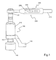
- the device shown in the figure for generating a torque-accurate torque comprises a torque multiplier, in general Both the input and the output shaft each end, for example, with a square, to which acts in the case of the input shaft, a torque wrench 200 and the case in the case of the input shaft the output shaft 102 in a so-called "power nut” or simply “nut” 140 engages.
- a torque multiplier 100 further includes a known reaction arm 130 which prevents the torque multiplier from spinning during the tightening operation by striking a stationary object.
- the torque multiplier 100 is manually operated by a torque wrench 200.
- the torque wrench 200 has a handle 210.
- the torque wrench 200 itself is an electronic torque wrench 200 having a display 205 and an input device 220.
- the input device 220 serves, for example, for inputting data characterizing the screwdriving process.
- the adjustment of the torque wrench 200 via a selection menu. After selecting a menu item, the desired output torque and the desired limit values are entered.
- an operator is visually informed of the progress, for example by means of light bars. Shortly before reaching the target torque, the operator can also be informed by an acoustic signal.
- a likewise preferably optical and optionally also acoustic "okay” or “non-kay” display is performed and the torque value achieved is stored in a data memory provided in the torque wrench 200 (not shown). All values stored in the torque wrench can be transferred to a PC or laptop after completion of all work and further evaluated there.
- the torque wrench is battery or battery operated.
- the torque multiplier 100 or the transmission gear 110 of the torque multiplier 100 has an RFID transponder which cooperates with an RFID reader arranged in the torque wrench 200.
- the torque wrench 200 effectively recognizes the torque multiplier 100 or the transmission 110 of the torque multiplier 100 and by resorting to values stored in the memory of the torque wrench 200 which were determined and stored in a common calibration to be described in greater detail below Torque values can be set exactly.
- translation values are stored, which are each associated with the transmission 110 of the torque multiplier 100. These values are used in a computing unit provided in the torque wrench 200.
- the combination of RFID transponder and RFID reader completely excludes system confusion.
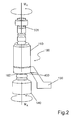
- Fig. 2 schematically a side view of the torque multiplier 100 is shown.
- An input shaft 101 terminating in, for example, a square on which the electronic torque wrench 200 engages is engaged via the transmission 110 with an output shaft which also terminates with a square 102 which engages a keyed nut, also referred to as a "power nut" 140 ,
- the power nut 140 is adapted on the output side to the screw head or to the nut of the screw connection.
- the transmission ratio between input torque M E and output torque M A is determined by the transmission 110. It is first determined this gear ratio, wherein the input torque M E is determined by the electronic torque wrench 200, and the output torque M A is detected by a sensor 400 which is arranged on the output shaft. This sensor 400 is intended only for calibration. In later operation, the arrangement of such a sensor 400 is not required.
- the determination of the transmission ratio now takes place in that the output shaft and thus the output square 102 are first brought into a first position, which corresponds to an angle of 0 ° ( Fig. 3b1 )). Then, the screw is "tightened" by the input torque M E is applied and the output torque M A is determined. This results in a functional relationship between the output torque M A and the input torque M E , the in Fig. 4 is shown schematically by a dashed line. In principle, such a series of measurements suffices for determining this functional relationship between the output torque M A and the input torque M E. In this case, the interpolation curve of the function M A (M E ) is then determined and this interpolation curve, in particular an interpolation straight line, as in FIGS FIGS. 4 and 5 represented, saved as a kind of characteristic.
- a particularly advantageous embodiment of the method according to the invention provides further measurement series.
- the output square 102 that is to say the output shaft, is rotated by 90 °, as shown on the right in FIG Fig. 3b2 ) is shown schematically and again the relationship between output torque M A and input torque M E is determined, in Fig. 4 shown as a solid line.
- the interpolation curve (the straight line shown) is formed over the entire torque range.
- the curve, as in Fig. 5 is divided, for example, into four sub-areas I, II, III, IV of the input torque M E is divided and an interpolation is performed in each of these sub-areas. Again, this results in a substantially linear course.
- the number of these subdivisions can be further increased, so that in the limit case an exact approximation of the function M A (M E ) is possible.
- the sensor 400 is removed and the dependence of the output torque M A on the input torque M E is - as mentioned - stored in the memory of the electronic torque wrench 200 and used in later schrauben. In this way, very accurately the tightening torque of screw can be determined.
- the calibration over different angular ranges is required because all known types of transmissions have due to the engagement conditions of the tooth flanks more or less sinusoidal fluctuations in the torque curve and thus the force curve. This means that over the entire torque curve of the torque multiplier deviations from theoretically calculated torque are detectable. Due to the calibration, these deviations can be taken into account and eliminated.
Landscapes
- Engineering & Computer Science (AREA)
- Mechanical Engineering (AREA)
- Details Of Spanners, Wrenches, And Screw Drivers And Accessories (AREA)
Description
- Die Erfindung betrifft eine Vorrichtung zur Erzeugung eines drehmomentgenauen Anzugsmoments für Schraubverbindungen nach dem Oberbegriff des Anspruchs 1 und ein Verfahren zur Kalibrierung einer solchen Vorrichtung nach dem Oberbegriff des Anspruchs 6.
- Drehmomentschlüssel und Drehmomentvervielfältiger sind in unterschiedlicher Ausführungsform aus dem Stand der Technik bekannt.
- So offenbart die
WO 2009/115889 A1 einen elektronischen Drehmomentschlüssel mit austauschbaren Drehmomentsensoren, der kalibriert ist, um ein definiertes Drehmoment zu erzeugen. - Aus der
DE 32 37 325 A1 geht ein Getriebe-Kraftschlüssel mit Überlastsicherung hervor, der eine Übersetzung des aufgewendeten Drehmoments ermöglicht und insoweit einen Drehmomentvervielfältiger darstellt. Dieser zeichnet sich dadurch aus, dass bei Erreichen eines gewünschten Anzugsmoments die Drehmomentübertragung durch eine Überlastsicherung unterbrochen wird. Mit einem solchen Getriebe-Kraftschlüssel können hochpräzise Anzugsmomente nicht realisiert werden. - Ein Drehmomentschlüssel mit einem RFID-Leser und mit einer RFID-Antenne zur Identifikation des Drehmomentschlüssels ist in der
US 2008/0115636 A1 offenbart. Mit einem solchen Drehmomentschlüssel kann festgestellt werden, ob ein gewünschtes Drehmoment erzeugt wurde. - Drehmomentvervielfältiger, nachfolgend auch Kraftvervielfältiger genannt, weisen im Allgemeinen hochübersetzte Planetengetriebe auf. Auch Stirnradgetriebe oder epizykloidische Getriebe werden vereinzelt bei Drehmomentvervielfältigern eingesetzt. Das Eingangsmoment wird dabei manuell eingestellt und zumeist mit Hilfe einer Ratsche oder mit Hilfe eines Drehmomentschlüssels erzeugt. Das Ausgangsmoment des Getriebes kann dann anhand eines zuvor ermittelten und bekannten und beispielsweise in einer Tabelle gespeicherten Übersetzungsverhältnisses bestimmt werden. Dabei wird jedoch der Getriebewirkungsgrad nicht berücksichtigt. Alternativ wird das Ausgangsmoment einer Drehmoment-Einstelltabelle, die ebenfalls zuvor ermittelt wird, entnommen. Hierbei wird der Getriebewirkungsgrad berücksichtigt, wobei bei Zwischenwerten eine Interpolation vorgenommen wird.
- Es besteht nun der Wunsch, im Rahmen der Qualitätssicherung mit manuellen Drehmoment- bzw. Kraftvervielfältigern die aufgebrachten Drehmoment-Werte stichprobenartig zu überprüfen und zu dokumentieren.
- Zur Erfassung des Drehmoments sind hierfür unterschiedliche Vorrichtungen und Verfahren bekannt. Eine erste aus dem Stand der Technik bekannte Lösung sieht vor, in dem Getriebe des Kraftvervielfältigers einen Drehmomentsensor zu integrieren. Der Sensor muss in diesem Falle über ein externes Auswertegerät, auch Datenlogger genannt, mit Energie versorgt werden. In diesem werden die Daten aufgezeichnet und gespeichert.
- Eine andere aus dem Stand der Technik bekannte Lösung sieht einen dem Kraftvervielfältiger nachgeschalteten Drehmomentsensor vor. Hierbei wird auf der Abtriebswelle des Getriebes ein geeigneter Drehmomentsensor angeordnet. Auch hier erfolgt die Energieversorgung und Datenaufzeichnung mittels eines kabelgebundenen externen Geräts.
- Bei beiden aus dem Stand der Technik bekannten Lösungen erfolgt die Energieversorgung des Sensors bzw. die Datenauswertung und Speicherung von außerhalb bzw. außerhalb. Hierzu sind elektrische Leitungen in Form von Kabeln und Auswertegeräte erforderlich, die harten Baustellenbedingungen ausgesetzt sind. Dabei werden oftmals die empfindlichen, frei verlegten Kabel versehentlich abgerissen oder beschädigt. Auch sind Steckverbindungen vorgesehen, die bei Kontakt mit anderen Bauteilen beschädigt und verbogen werden können. Auch sogenannte Schnittstellenbüchsen, die Steckverbindungen für die Kabel enthalten, und auf dem Getriebegehäuse als zusätzliches und über das Getriebegehäuse hinaus ragendes, in der Regel quaderförmig ausgebildetes Gehäuse angeordnet sind, können beschädigt werden. Nachteilig ist es auch, dass die erforderlichen Auswertegeräte zusätzlich zu den anderen Einrichtungen vom Bediener entweder umgehängt oder in Form von Gürteltaschen oder dergleichen getragen werden müssen. Die Datenübertragung zwischen den Sensoren und dem Auswertegerät erfolgt dabei zumeist über "fliegende" Kabel, die den Bediener zusätzlich behindern.
- Der Erfindung liegt daher die Aufgabe zugrunde, eine Vorrichtung zu vermitteln, welche es dem Bediener erlaubt, ohne Einschränkungen durch Kabel oder externe Geräte eingesetzt zu werden und andererseits die größtmögliche Sicherheit bei der Ermittlung des Ausgangsdrehmoments sicherstellen.
- Die Aufgabe wird durch eine Vorrichtung zur Erzeugung eines drehmomentgenauen Anzugsmoments für Schraubverbindungen nach Anspruch 1 gelöst. Vorteilhafte Weiterbildungen und Ausgestaltungen der erfindungsgemäßen Vorrichtung sind Gegenstand der auf Anspruch 1 rückbezogenen Unteransprüche.
- So sieht eine vorteilhafte Weiterbildung der erfindungsgemäßen Vorrichtung vor, dass der elektronische Drehmomentschlüssel ein Display zu Anzeige des eingangs beschriebenen Ausgangsmoments aufweist, wobei Eingangs- und Ausgangsmoment auf das Getriebe bezogen sind.
- In dem Speicher ist - neben anderen Daten - vorteilhafterweise auch das bei der Kalibrierung ermittelte Übersetzungsverhältnis des Drehmomentvervielfältigers gespeichert.
- Das Übersetzungsverhältnis ist bevorzugt als Interpolationskurve des funktionalen Zusammenhangs des Ausgangsdrehmoments in Abhängigkeit von dem Eingangsdrehmoment des Drehmomentvervielfältigers in dem Speicher hinterlegt.
- Eine besonders vorteilhafte Ausführungsform sieht vor, dass das Getriebe einen RFID-Transponder und der Drehmomentschlüssel einen RFID-Reader aufweisen, die aufeinander abgestimmt sind. In diesem Falle erkennt der Drehmomentschlüssel das Getriebe. Es können im Speicher hinterlegte, das Getriebe charakterisierende Daten zur Ermittlung des Anzugsmoments der Schraubverbindungen verwendet werden.
- Der Erfindung liegt ferner die Aufgabe zugrunde, ein Verfahren zu vermitteln, welches auf einfache Weise eine gemeinsame Kalibrierung von Drehmomentvervielfältigern und elektronischen Drehmomentschlüsseln ermöglicht, wobei insbesondere spezifische Daten des Drehmomentvervielfältigers und insbesondere dessen Getriebe bei der Kalibrierung berücksichtigt werden sollen.
- Diese Aufgabe wird gelöst durch ein Verfahren zur Kalibrierung einer Vorrichtung zur Erzeugung eines drehmomentgenauen Anzugsmoments für Schraubverbindungen mit den Merkmalen des Anspruchs 6. Die gemeinsame Kalibrierung des Drehmomentvervielfachers zusammen mit dem elektronischen Drehmomentschlüssel erfolgt dabei so, dass das Übersetzungsverhältnis anhand mindestens eines über den gesamten Drehmomentbereich gewonnenen Durchschnittswertes erfolgt. Dieses so bestimmte Übersetzungsverhältnis wird in dem Speicher des Drehmomentschlüssels gespeichert und bei der Bestimmung des Anzugsmoments der Schraubverbindung bei späteren Schraubvorgängen berücksichtigt.
- Dabei wird das tatsächliche Übersetzungsverhältnis über den gesamten Drehmomentbereich bei verschiedenen Winkelstellungen der Ausgangswelle des Drehmomentvervielfachers ermittelt und gespeichert. Hierzu wird zunächst das Übersetzungsverhältnis über den gesamten Drehmömentbereich bei einem ersten Winkel bestimmt und gespeichert, sodann wird die Ausgangswelle um vorgebbare Winkel weitergedreht und jeweils bei diesen Winkelstellungen über den gesamten Drehmomentbereich das Übersetzungsverhältnis ermittelt und gespeichert.
- Die Ausgangswelle wird hierzu um jeweils Winkel von 90° weitergedreht so lange, bis sie insgesamt um einen Winkel von 180° verdreht ist. Diesem Weiterdrehen um vorgebbare Winkel liegt die Erkenntnis zugrunde, dass der Drehmomentverlauf des Ausgangsdrehmoments in Abhängigkeit vom Eingangsdrehmoment im Wesentlichen einen periodischen Verlauf zeigt, der durch eine Sinus- bzw. Cosinusfunktion beschrieben werden kann. Ein Weiterdrehen um jeweils Vielfache von 90° ermöglichen die Bestimmung dieses periodischen Sinus-/Cosinusverlaufs. Wenn um kleinere Winkel als 90° jeweils weitergedreht wird, beispielsweise um 45°, so muss so oft weitergedreht werden, bis eine Drehung der Ausgangswelle des Drehmomentvervielfachers um 180° stattgefunden hat. Aus den so gewonnenen Werten wird danach ein mittleres Übersetzungsverhältnis errechnet und in dem Speicher des elektronischen Drehmomentschlüssels hinterlegt.
- Eine vorteilhafte Ausgestaltung des Verfahrens ist Gegenstand des auf Anspruch 6 rückbezogenen Unteranspruchs. So wird vorteilhafterweise eine Interpolationskurve, in erster Näherung eine Interpolationsgerade zwischen die auf diese Weise bei unterschiedlichen Winkelverhältnissen ermittelten Übersetzungsverhältnisse gelegt und aufgrund dieser Interpolationskurve das Ausgangsdrehmoment in Abhängigkeit von dem Eingangsdrehmoment bestimmt.
- Ausführungsbeispiele der Erfindung sind in den Zeichnungen dargestellt und in der nachfolgenden Beschreibung näher erläutert.
- In den Figuren zeigen:
- Fig. 1
- schematisch eine von der Erfindung Gebrauch machende Vorrichtung zur Erzeugung eines drehmomentgenauen Anzugsmoments für Schraubverbindungen;
- Fig. 2
- der Drehmomentvervielfältiger der in
Fig. 1 dargestellten Vorrichtung; - Fig. 3
- eine Draufsicht auf den in
Fig. 2 dargestellten Drehmomentvervielfältiger; - Fig. 4
- das Ausgangsdrehmoment über dem Eingangsdrehmoment und
- Fig. 5
- das Ausgangsdrehmoment über dem Eingangsdrehmoment zur Erläuterung einer Variante des erfindungsgemäßen Verfahrens.
- Die in der Figur dargestellte Vorrichtung zur Erzeugung eines drehmomentgenauen Anzugsmoments umfasst einen Drehmomentvervielfältiger, im allgemeinen Sprachgebrauch und nachfolgend auch kurz Kraftvervielfältiger 100 genannt, der eine Eingangswelle 101 aufweist und eine Ausgangs- bzw. Abtriebswelle 102. Sowohl Eingangs- als auch Abtriebswelle enden jeweils beispielsweise mit einem Vierkant, an dem im Falle der Eingangswelle ein Drehmomentschlüssel 200 angreift und der im Falle der Abtriebswelle 102 in eine sogenannte "Kraftnuss" oder einfach "Nuss" 140 eingreift. Mittels der Nuss 140 wird ein Anzugsmoment auf eine (nicht dargestellte) Schraubverbindung übertragen. Der Drehmomentvervielfältiger 100 weist darüber hinaus einen an sich bekannten Reaktionsarm 130 auf, der ein Durchdrehen des Drehmomentvervielfältigers während des Schraubvorgangs durch Anschlagen an einem ortsfesten Gegenstand verhindert.
- Der Drehmomentvervielfältiger 100 wird durch einen Drehmomentschlüssel 200 manuell betätigt. Hierzu weist der Drehmomentschlüssel 200 einen Griff 210 auf. Der Drehmomentschlüssel 200 selbst ist ein elektronischer Drehmomentschlüssel 200 mit einem Display 205 und einer Eingabeeinrichtung 220. Die Eingabeeinrichtung 220 dient beispielsweise zur Eingabe von den Schraubvorgang charakterisierenden Daten. Die Einstellung des Drehmomentschlüssels 200 erfolgt über ein Auswahlmenü. Nach Auswahl eines Menüpunktes werden das gewünschte Ausgangsmoment sowie die gewünschten Grenzwerte eingegeben. Während der Aufbringung des Drehmoments wird eine Bedienungsperson visuell über den Fortschritt, beispielsweise mittels Leuchtbalken, informiert. Kurz vor Erreichen des Zielmomentes kann die Bedienungsperson zusätzlich über ein akustisches Signal informiert werden. Nach Erreichen des Drehmomentes erfolgt eine ebenfalls bevorzugt optische und gegebenenfalls auch akustische "Okay" bzw. "Nichtokay"-Anzeige und der erreichte Wert des Drehmoments wird in einem Datenspeicher, der im Drehmomentschlüssel 200 vorgesehen ist (nicht dargestellt), gespeichert. Alle in dem Drehmomentschlüssel gespeicherten Werte können nach Abschluss sämtlicher Arbeiten an einen PC oder Laptop übertragen und dort weiter ausgewertet werden.
- Grundidee der Erfindung ist es, zum einen eine autarke Vorrichtung zu vermitteln, welche ohne zusätzliche Kabel, eine externe Stromversorgung, entfernte Eingabe- und Anzeigegeräte und dergleichen auskommt. Hierzu ist der Drehmomentschlüssel batterie- oder akkubetrieben. Darüber hinaus kann vorgesehen sein, dass der Drehmomentvervielfältiger 100 bzw. das Übersetzungsgetriebe 110 des Drehmomentvervielfältigers 100 einen RFID-Transponder aufweist, der mit einem in dem Drehmomentschlüssel 200 angeordneten RFID-Reader zusammenwirkt. In diesem Falle erkennt der Drehmomentschlüssel 200 gewissermaßen den Drehmomentvervielfältiger 100 bzw. das Getriebe 110 des Drehmomentvervielfältigers 100 und durch Rückgriff auf in dem Speicher des Drehmomentschlüssels 200 gespeicherte Werte, die in einer zuvor und nachfolgend noch näher zu beschreibenden gemeinsamen Kalibrierung ermittelt und gespeichert wurden, können Drehmomentwerte exakt eingestellt werden. In dem Speicher sind hierzu Übersetzungswerte gespeichert, die jeweils dem Getriebe 110 des Drehmomentvervielfältigers 100 zugeordnet sind. Diese Werte werden in einer in dem Drehmomentschlüssel 200 vorgesehenen Recheneinheit verwendet. Durch die Kombination aus RFID-Transponder und RFID-Reader sind Systemverwechslungen vollständig ausgeschlossen.
- Die Kalibrierung des Systems aus Drehmomentvervielfältiger 100 und Drehmomentschlüssel 200 erfolgt dadurch, dass zunächst das tatsächliche Übersetzungsverhältnis über den gesamten Drehmomentbereich des Drehmomentvervielfältigers 100 ermittelt wird. Das Verfahren dieser Kalibrierung wird nachfolgend anhand der
Figuren 2 bis 5 erläutert. InFig. 2 ist schematisch eine Seitenansicht des Drehmomentvervielfältiger 100 dargestellt. Eine Eingangswelle 101, die mit einem beispielsweise Vierkant endet, an dem der elektronische Drehmomentschlüssel 200 angreift, ist über das Getriebe 110 mit einer Ausgangswelle, die ebenfalls mit einem Vierkant 102 endet, der in eine Schlüsselnuss, auch als "Kraftnuss" 140 bezeichnet, eingreift. Die Kraftnuss 140 ist abtriebsseitig an den Schraubenkopf bzw. an die Mutter der Schraubverbindung angepasst. An der Eingangswelle wird ein Eingangsmoment ME aufgebracht und am Ausgang des Getriebes 110 liegt ein Ausgangsmoment MA an. Das Übersetzungsverhältnis zwischen Eingangsmoment ME und Ausgangsmoment MA wird durch das Getriebe 110 bestimmt. Es wird zunächst dieses Übersetzungsverhältnis bestimmt, wobei das Eingangsmoment ME durch den elektronischen Drehmomentschlüssel 200 ermittelt wird, und das Ausgangsdrehmoment MAdurch einen Sensor 400, der an der Ausgangswelle angeordnet ist, erfasst wird. Dieser Sensor 400 ist nur bei der Kalibrierung vorgesehen. Im späteren Betrieb ist die Anordnung eines solchen Sensors 400 nicht erforderlich. - Die Ermittlung des Übersetzungsverhältnisses erfolgt nun dadurch, dass die Ausgangswelle und damit der Ausgangsvierkant 102 zunächst in eine erste Position gebracht werden, die einem Winkel von 0° entspricht (
Fig. 3b1 )). Sodann wird die Schraubverbindung "angezogen", indem das Eingangsmoment ME aufgebracht wird und das Ausgangsmoment MA ermittelt wird. Dabei ergibt sich ein funktionaler Zusammenhang zwischen dem Ausgangsmoment MA und dem Eingangsmoment ME, der inFig. 4 schematisch durch eine gestrichelte Linie dargestellt ist. Rein prinzipiell genügt eine solche Messreihe zur Bestimmung dieses funktionalen Zusammenhangs zwischen dem Ausgangsmoment MA dem Eingangsmoment ME. In diesem Falle wird dann die Interpolationskurve der Funktion MA(ME) bestimmt und diese Interpolationskurve, insbesondere eine Interpolationsgerade, wie in denFiguren 4 und5 dargestellt, gewissermaßen als Kennlinie gespeichert. - Um die Genauigkeit weiter zu steigern, sieht eine besonders vorteilhafte Ausgestaltung des erfindungsgemäßen Verfahrens weitere Messreihen vor.
- In einer zweiten Messreihe wird der Ausgangsvierkant 102, das heißt die Ausgangswelle um 90° verdreht, wie es rechts in
Fig. 3b2 ) schematisch dargestellt ist und wiederum wird der Zusammenhang zwischen Ausgangsmoment MA und Eingangsmoment ME bestimmt, inFig. 4 als durchgezogene Linie dargestellt. - Schließlich wird in einer dritten Messreihe die Ausgangswelle und damit der Ausgangsvierkant 102 um weitere 90° (
Fig. 3b3 )) verdreht und es wird wiederum die Abhängigkeit des Ausgangsdrehmoments MA von dem Eingangsdrehmoment ME bestimmt. Dies ist inFig. 4 durch eine gepunktete Linie dargestellt. Aus diesen drei Linien wird sodann eine Interpolationskurve, in erster Näherung eine Interpolationsgerade bestimmt, die in einem Speicher 250 des Drehmomentschlüssels 200 gespeichert wird und welche die Abhängigkeit des Ausgangsdrehmoments MA von dem Eingangsdrehmoment ME repräsentiert. - Bei der in
Fig. 4 dargestellten Ausgestaltung wird die Interpolationskurve (die dargestellte Gerade) über den gesamten Drehmomentbereich gebildet. Eine weitere Erhöhung der Genauigkeit ergibt sich, wenn zur Bestimmung der Interpolation die Kurve, wie inFig. 5 dargestellt, beispielsweise in vier Unterbereiche I, II, III, IV des Eingangsdrehmoments ME unterteilt wird und in jedem dieser Teilbereiche eine Interpolation vorgenommen wird. Auch hier ergibt sich ein im Wesentlichen linearer Verlauf. Die Zahl dieser Unterteilungen kann weiter erhöht werden, sodass im Grenzfalle eine exakte Approximation der Funktion MA(ME) möglich ist. Nach Abschluss der Kalibrierungen Wird der Sensor 400 entfernt und die Abhängigkeit des Ausgangsdrehmoments MA von dem Eingangsdrehmoment ME wird - wie erwähnt - in dem Speicher des elektronischen Drehmomentschlüssels 200 gespeichert und bei späteren Schraubfällen verwendet. Auf diese Weise kann sehr genau das Anzugsmoment von Schraubverbindungen bestimmt werden. - Die Kalibrierung über verschiedenen Winkelbereiche ist erforderlich, da alle bekannten Getriebearten aufgrund der Eingriffsverhältnisse der Zahnflanken mehr oder weniger sinusförmige Schwankungen des Drehmomentverlaufs und damit des Kraftverlaufs aufweisen. Dies bedeutet, dass über den gesamten Drehmomentverlauf des Drehmomentvervielfältigers Abweichungen vom theoretisch errechneten Drehmoment nachweisbar sind. Durch die Kalibrierung können diese Abweichungen berücksichtigt und eliminiert werden.
Claims (7)
- Vorrichtung zur Erzeugung eines drehmomentgenauen Anzugsmoments für Schraubverbindungen mit einer Kombination aus Drehmomentvervielfältiger (100) und einem an diesen angepassten und zusammen mit diesem kalibrierten Drehmomentschlüssel (200), wobei der Drehmomentschlüssel (200) eine Eingabeeinheit (220) zur Eingabe eines Drehmoment-Grenzwertes aufweist und dass der Drehmomentschlüssel (200) einen Speicher (250) zur Speicherung der das Anzugsmoment charakterisierenden Daten aufweist.
- Vorrichtung nach Anspruch 1, dadurch gekennzeichnet, dass der Drehmomentschlüssel (200) ein Display (205) zu Anzeige eines Eingangs- und Ausgangsmoments aufweist.
- Vorrichtung nach Anspruch 1, dadurch gekennzeichnet, dass in dem Speicher das bei der Kalibrierung ermittelte Übersetzungsverhältnis des Drehmomentvervielfältigers (100) gespeichert ist.
- Vorrichtung nach Anspruch 3, dadurch gekennzeichnet, dass das Übersetzungsverhältnis als Interpolationskurve des funktionalen Zusammenhangs des Ausgangsdrehmoments (MA) in Abhängigkeit von dem Eingangsdrehmoment (ME) des Drehmomentvervielfältigers (100) in dem Speicher (250) hinterlegt ist.
- Vorrichtung nach einem der Ansprüche 1 bis 4, dadurch gekennzeichnet, dass der Drehmomentvervielfältiger (100) einen RFID-Transponder aufweist und dass der Drehmomentschlüssel (200) einen RFID-Reader aufweist, die miteinander kommunizieren und mittels denen eine Übertragung des charakteristischen Übersetzungsverhältnisses des Drehmomentvervielfältigers (100) an den Drehmomentschlüssel (200) erfolgt.
- Verfahren zur Kalibrierung einer Vorrichtung zur Erzeugung eines drehmomentgenauen Anzugsmoments für Schraubverbindungen nach einem der Ansprüche 1 bis 5, wobei als Übersetzungsverhältnis das Ausgangsdrehmoment (MA) in Abhängigkeit von dem Eingangsdrehmoment (ME) über den gesamten Drehmomentverlauf bestimmt wird und dass das Übersetzungsverhältnis (MA(ME)) anhand mindestens eines über den gesamten Drehmomentbereich gewonnenen Durchschnittswertes erfolgt, dass das Übersetzungsverhältnis bei mehreren Getriebeeingriffswinkeln (0°, 90°, 180°) bestimmt wird und dass zunächst über den gesamten vorgebbaren Drehmomentbereich das tatsächliche Übersetzungsverhältnis ermittelt wird und dass danach eine Ausgangswelle des Drehmomentvervielfältigers (100) um jeweils vorgebbare Winkel, insbesondere zweimal um 90° weitergedreht wird und dabei das Übersetzungsverhältnis über den gesamten Drehmomentbereich ermittelt und hieraus ein mittleres Übersetzungsverhältnis errechnet wird, das in dem Speicher (250) des Drehmomentschlüssels (200) hinterlegt wird.
- Verfahren nach Anspruch6, dadurch gekennzeichnet, dass der Durchschnittswert durch Bilden einer Interpolationskurve, insbesondere einer Interpolationsgeraden, ermittelt wird.
Priority Applications (1)
| Application Number | Priority Date | Filing Date | Title |
|---|---|---|---|
| PL11779553T PL2566660T3 (pl) | 2010-05-06 | 2011-05-03 | Urządzenie do wytwarzania dokładnego dynamometrycznie momentu dokręcającego do połączeń śrubowych |
Applications Claiming Priority (2)
| Application Number | Priority Date | Filing Date | Title |
|---|---|---|---|
| DE102010019792A DE102010019792A1 (de) | 2010-05-06 | 2010-05-06 | Vorrichtung zur Erzeugung eines drehmomentgenauen Anzugsmoments für Schraubverbindungen und Verfahren zur Kalibrierung einer solchen Vorrichtung |
| PCT/DE2011/001020 WO2012019575A1 (de) | 2010-05-06 | 2011-05-03 | Vorrichtung zur erzeugung eines drehmomentgenauen anzugsmoments für schraubverbindungen |
Publications (2)
| Publication Number | Publication Date |
|---|---|
| EP2566660A1 EP2566660A1 (de) | 2013-03-13 |
| EP2566660B1 true EP2566660B1 (de) | 2018-07-11 |
Family
ID=44802908
Family Applications (1)
| Application Number | Title | Priority Date | Filing Date |
|---|---|---|---|
| EP11779553.4A Not-in-force EP2566660B1 (de) | 2010-05-06 | 2011-05-03 | Vorrichtung zur erzeugung eines drehmomentgenauen anzugsmoments für schraubverbindungen |
Country Status (9)
| Country | Link |
|---|---|
| US (1) | US20130047799A1 (de) |
| EP (1) | EP2566660B1 (de) |
| CN (1) | CN103003027B (de) |
| BR (1) | BR112012028314A2 (de) |
| DE (1) | DE102010019792A1 (de) |
| ES (1) | ES2690170T3 (de) |
| PL (1) | PL2566660T3 (de) |
| RU (1) | RU2530182C2 (de) |
| WO (1) | WO2012019575A1 (de) |
Families Citing this family (27)
| Publication number | Priority date | Publication date | Assignee | Title |
|---|---|---|---|---|
| CN102374923B (zh) * | 2010-08-23 | 2014-06-04 | 浙江吉利汽车有限公司 | 多功能扳手扭力校准仪 |
| US8776644B2 (en) * | 2012-01-23 | 2014-07-15 | Stanley Black & Decker, Inc. | Electronic identifier attachment for inventory items |
| TW201441594A (zh) * | 2013-04-16 | 2014-11-01 | Huang Kuan Auto Control Equipment Co Ltd | 扭力測試裝置 |
| EP2988908B1 (de) * | 2013-04-24 | 2020-06-10 | Hytorc Division Unex Corporation | Vorrichtung zum anziehen von befestigungselementen mit gewinde |
| US9242356B2 (en) | 2013-05-07 | 2016-01-26 | Snap-On Incorporated | Method of calibrating torque using peak hold measurement on an electronic torque wrench |
| US9156148B2 (en) * | 2013-05-10 | 2015-10-13 | Snap-On Incorporated | Preset electronic torque tool |
| ES2581928T3 (es) * | 2013-08-08 | 2016-09-08 | Mikawa Co., Ltd. | Multiplicador de par |
| CN104290069B (zh) * | 2014-09-19 | 2016-03-02 | 燕山大学 | 组合式蛇形力矩扳手 |
| CN104192734B (zh) * | 2014-09-19 | 2017-02-22 | 东莞市毅新庆江机械制造有限公司 | 一种塔机用高强螺栓能达到给定预紧力矩的通用操作方法 |
| US9664583B2 (en) * | 2014-11-02 | 2017-05-30 | Matatakitoyo Tool Co., Ltd. | Device for calibrating a torque wrench |
| RU2598755C1 (ru) * | 2015-04-06 | 2016-09-27 | Закрытое акционерное общество "ИНСТРУМ-РЭНД" | Пневматический гайковёрт с электронным контролем момента |
| RU2735529C2 (ru) * | 2016-02-04 | 2020-11-03 | Книпекс-Верк К. Густав Пуч Кг | Ручной инструмент |
| CN106556540B (zh) * | 2016-10-19 | 2019-09-10 | 奇瑞汽车股份有限公司 | 一种凸焊螺母焊接强度检测工装 |
| US11034003B2 (en) | 2016-12-02 | 2021-06-15 | Snap-On Incorporated | Holding tool |
| DE102017002440A1 (de) * | 2017-03-13 | 2018-09-13 | Liebherr-Components Biberach Gmbh | Verfahren und Vorrichtung zum Anziehen von Verschraubungen |
| CN107505073B (zh) * | 2017-08-10 | 2020-04-17 | 成都楠迪科技有限公司 | 便携式智能扭力测试系统及测试流程 |
| DE102017008859B3 (de) * | 2017-09-21 | 2018-11-29 | Alki Technik Gmbh Schraubsysteme Entwicklung-Produktion-Vertrieb | Kalibrierverfahren für einen Kraftschrauber |
| CN107782489A (zh) * | 2017-10-16 | 2018-03-09 | 郑州拽亘电子科技有限公司 | 螺栓模拟器及使用该模拟器的扭矩板子检定装置 |
| EP3501739A1 (de) * | 2017-12-21 | 2019-06-26 | Aliki Technik GmbH Schraubsysteme Entwicklung- Produktion-Vertrieb | Verfahren zur kalibrierung und steuerung einer schraubvorrichtung und vorrichtung zur durchführung des verfahrens |
| IT201800006565A1 (it) * | 2018-06-21 | 2019-12-21 | Enrico Fassio | Dispositivo elettronico per la rilevazione e la visualizzazione della coppia torsiometrica istantanea applicata mediante qualsiasi utensile |
| DE102018118853A1 (de) | 2018-08-02 | 2020-02-06 | Johannes Lübbering Gmbh | Schraubvorrichtung, Antriebsdrehmomenterzeugungsmittel, Verschraubsystem sowie Verfahren zur Drehmomentsteuerung |
| CN111843528A (zh) * | 2019-04-30 | 2020-10-30 | 北京航天新风机械设备有限责任公司 | 一种可控制预紧力的装夹装置 |
| CN110153935A (zh) * | 2019-05-22 | 2019-08-23 | 哈尔滨万科科技有限公司 | 数字传输电扭力扳手 |
| US11919141B2 (en) * | 2019-08-27 | 2024-03-05 | Ingersoll-Rand Industrial U.S., Inc. | Tool with wireless switch |
| US11931878B2 (en) | 2019-08-27 | 2024-03-19 | Ingersoll-Rand Industrial U.S., Inc. | Quick change auxiliary handle for power tool |
| US12061128B2 (en) * | 2021-07-08 | 2024-08-13 | Rtx Corporation | Torque loading in component stack assembly |
| US12215729B2 (en) * | 2021-12-08 | 2025-02-04 | Mueller International, Llc | Smart operating nut |
Family Cites Families (16)
| Publication number | Priority date | Publication date | Assignee | Title |
|---|---|---|---|---|
| US3199384A (en) * | 1962-06-01 | 1965-08-10 | Brase George | Pipe nipple wrench with torque booster |
| DE3237325A1 (de) * | 1982-10-08 | 1984-04-12 | Mierbach, Hans B., 5300 Bonn | Getriebe- kraftschluessel mit ueberlastsicherung |
| CN2050363U (zh) * | 1989-02-23 | 1990-01-03 | 中船总公司第七○三研究所 | 数显扭力扳手 |
| CN2106043U (zh) * | 1991-11-25 | 1992-06-03 | 卞正谟 | 传动增力器 |
| RU2200654C2 (ru) * | 1999-10-27 | 2003-03-20 | Гузевич Юрий Дмитриевич | Ключ-мультипликатор |
| US7090030B2 (en) * | 2002-09-03 | 2006-08-15 | Microtorq L.L.C. | Tranducerized torque wrench |
| AU2003287041A1 (en) * | 2002-10-16 | 2004-05-04 | Snap-On Incorporated | Ratcheting torque-angle wrench and method |
| RU2235299C1 (ru) * | 2002-11-25 | 2004-08-27 | Открытое акционерное общество "Чебоксарский завод промышленных тракторов" | Динамометрический ключ |
| EP1591206B1 (de) * | 2004-04-09 | 2015-02-11 | Stanley Works (Europe) GmbH | Drehmoment-Werkzeug, insbesondere Schlüssel und Verfahren zur Detektion des Endes eines Gleichgewichtszustands während der Aufbringung eines Drehmoments |
| CN200945596Y (zh) * | 2006-08-14 | 2007-09-12 | 上海斯巴洛克精密紧固件有限公司 | 增扭器 |
| JP4974643B2 (ja) * | 2006-10-30 | 2012-07-11 | 前田金属工業株式会社 | ボルト・ナット締付装置 |
| US20080115636A1 (en) * | 2006-11-17 | 2008-05-22 | General Electric | Radio frequency identification enabled wrench system and a method of operating the same |
| EP2159006A4 (de) * | 2007-06-18 | 2012-05-23 | Tohnichi Mfg Co Ltd | Drehmomentschrauber |
| ITMI20080462A1 (it) * | 2008-03-18 | 2009-09-19 | Atlas Copco Blm Srl | "chiave dinamometrica elettronica con sensori di coppia sostituibili" |
| TWM392713U (en) * | 2010-07-12 | 2010-11-21 | Legend Lifestyle Products Corp | Wireless torque wrench with angle correction feature |
| TWM397882U (en) * | 2010-08-12 | 2011-02-11 | Legend Lifestyle Products Corp | Torque multiplier |
-
2010
- 2010-05-06 DE DE102010019792A patent/DE102010019792A1/de not_active Withdrawn
-
2011
- 2011-05-03 EP EP11779553.4A patent/EP2566660B1/de not_active Not-in-force
- 2011-05-03 ES ES11779553.4T patent/ES2690170T3/es active Active
- 2011-05-03 CN CN201180022829.6A patent/CN103003027B/zh not_active Expired - Fee Related
- 2011-05-03 PL PL11779553T patent/PL2566660T3/pl unknown
- 2011-05-03 BR BR112012028314A patent/BR112012028314A2/pt not_active IP Right Cessation
- 2011-05-03 WO PCT/DE2011/001020 patent/WO2012019575A1/de not_active Ceased
- 2011-05-03 US US13/695,857 patent/US20130047799A1/en not_active Abandoned
- 2011-05-03 RU RU2012152452/02A patent/RU2530182C2/ru not_active IP Right Cessation
Non-Patent Citations (1)
| Title |
|---|
| None * |
Also Published As
| Publication number | Publication date |
|---|---|
| DE102010019792A1 (de) | 2011-11-10 |
| RU2012152452A (ru) | 2014-06-20 |
| ES2690170T3 (es) | 2018-11-19 |
| PL2566660T3 (pl) | 2019-02-28 |
| CN103003027A (zh) | 2013-03-27 |
| RU2530182C2 (ru) | 2014-10-10 |
| CN103003027B (zh) | 2016-08-03 |
| EP2566660A1 (de) | 2013-03-13 |
| BR112012028314A2 (pt) | 2016-11-01 |
| WO2012019575A1 (de) | 2012-02-16 |
| US20130047799A1 (en) | 2013-02-28 |
Similar Documents
| Publication | Publication Date | Title |
|---|---|---|
| EP2566660B1 (de) | Vorrichtung zur erzeugung eines drehmomentgenauen anzugsmoments für schraubverbindungen | |
| EP4197696B1 (de) | Schraubvorrichtung mit integrierten erfassungsmitteln | |
| DE102010040217B4 (de) | Betätigungsvorrichtung zum Kalibrieren von Drehmoment-Drehwinkelschlüsseln | |
| EP0133557A1 (de) | Ratschenhandschlüssel zum Anziehen von Schrauben | |
| EP2078590A2 (de) | Schraubvorrichtung und Verfahren zum Überwachen von Schraubvorgängen | |
| DE4316332C2 (de) | Schraubvorrichtung mit Erfassung, Überwachung und Regelung meßbarer Schraubenparameter während des Schraubvorganges und Verfahren zum Herstellen qualitativ hochwertiger Schraubverbindungen | |
| DE202009001997U1 (de) | Digital anzeigendes Anpassungsglied für ein Drehmomentwerkzeug | |
| DE4118595C2 (de) | Prüfgerät zum Überprüfen der Qualität von Schraubverbindungen | |
| EP3499203B1 (de) | Verfahren, vorrichtung und computerprogrammprodukt zur prozessfähigkeitsuntersuchung einer schraubverbindung | |
| DE102017008859B3 (de) | Kalibrierverfahren für einen Kraftschrauber | |
| EP2681010B1 (de) | System zur verarbeitung von messdaten- und/oder messparameterdaten | |
| DE202010006554U1 (de) | Vorrichtung zur Erzeugung eines drehmomentgenauen Anzugsmoments für Schraubverbindungen | |
| EP4289558B1 (de) | Verfahren und system zum freischalten eines kalibrierbaren elektronischen drehmomentwerkzeugs, drehmomentprüfvorrichtung und drehmomentwerkzeug | |
| DE102005013786A1 (de) | Maschinenfähigkeitsuntersuchung in Winkelschritten | |
| EP0785844A1 (de) | Drehmomentschlüssel | |
| DE19637540A1 (de) | Vorrichtung zur Prüfung von Drehmomentschlüsseln | |
| DE3607363A1 (de) | Schraubwerkzeug, insbesondere drehmoment-schraubenzieher | |
| DE202020006173U1 (de) | Aufsatzteil eines angetriebenen Werkzeuges | |
| DE102021130078B4 (de) | Warnstruktur für elektronische Drehmomentwerkzeuge | |
| WO2025237927A1 (de) | Schraubvorrichtung mit integrierten erfassungsmitteln | |
| DE202009006464U1 (de) | Drehmomentschlüssel | |
| DE102009025669B3 (de) | Andruckroller | |
| DE4137750C2 (de) | Vorrichtung zur Qualitätsüberwachung von Fügeprozessen zur Herstellung von Pressverbindungen | |
| EP1310779A1 (de) | Vorrichtung zum Messen von Drehmomenten und der Drehrichtung in einer Antriebsanordnung | |
| DE102014223187A1 (de) | Vorrichtung zur zerstörungsfreien Prüfung einer Nietverbindung, insbes. einer Blindnietverbindung |
Legal Events
| Date | Code | Title | Description |
|---|---|---|---|
| PUAI | Public reference made under article 153(3) epc to a published international application that has entered the european phase |
Free format text: ORIGINAL CODE: 0009012 |
|
| 17P | Request for examination filed |
Effective date: 20121123 |
|
| AK | Designated contracting states |
Kind code of ref document: A1 Designated state(s): AL AT BE BG CH CY CZ DE DK EE ES FI FR GB GR HR HU IE IS IT LI LT LU LV MC MK MT NL NO PL PT RO RS SE SI SK SM TR |
|
| DAX | Request for extension of the european patent (deleted) | ||
| 17Q | First examination report despatched |
Effective date: 20141105 |
|
| RAP1 | Party data changed (applicant data changed or rights of an application transferred) |
Owner name: GEDORE TORQUE SOLUTIONS GMBH |
|
| GRAP | Despatch of communication of intention to grant a patent |
Free format text: ORIGINAL CODE: EPIDOSNIGR1 |
|
| STAA | Information on the status of an ep patent application or granted ep patent |
Free format text: STATUS: GRANT OF PATENT IS INTENDED |
|
| INTG | Intention to grant announced |
Effective date: 20180215 |
|
| GRAA | (expected) grant |
Free format text: ORIGINAL CODE: 0009210 |
|
| STAA | Information on the status of an ep patent application or granted ep patent |
Free format text: STATUS: THE PATENT HAS BEEN GRANTED |
|
| AK | Designated contracting states |
Kind code of ref document: B1 Designated state(s): AL AT BE BG CH CY CZ DE DK EE ES FI FR GB GR HR HU IE IS IT LI LT LU LV MC MK MT NL NO PL PT RO RS SE SI SK SM TR |
|
| REG | Reference to a national code |
Ref country code: GB Ref legal event code: FG4D Free format text: NOT ENGLISH |
|
| REG | Reference to a national code |
Ref country code: CH Ref legal event code: EP |
|
| REG | Reference to a national code |
Ref country code: AT Ref legal event code: REF Ref document number: 1016396 Country of ref document: AT Kind code of ref document: T Effective date: 20180715 |
|
| GRAS | Grant fee paid |
Free format text: ORIGINAL CODE: EPIDOSNIGR3 |
|
| REG | Reference to a national code |
Ref country code: IE Ref legal event code: FG4D Free format text: LANGUAGE OF EP DOCUMENT: GERMAN |
|
| REG | Reference to a national code |
Ref country code: DE Ref legal event code: R096 Ref document number: 502011014448 Country of ref document: DE |
|
| REG | Reference to a national code |
Ref country code: NL Ref legal event code: MP Effective date: 20180711 |
|
| REG | Reference to a national code |
Ref country code: ES Ref legal event code: FG2A Ref document number: 2690170 Country of ref document: ES Kind code of ref document: T3 Effective date: 20181119 |
|
| REG | Reference to a national code |
Ref country code: LT Ref legal event code: MG4D |
|
| PG25 | Lapsed in a contracting state [announced via postgrant information from national office to epo] |
Ref country code: NL Free format text: LAPSE BECAUSE OF FAILURE TO SUBMIT A TRANSLATION OF THE DESCRIPTION OR TO PAY THE FEE WITHIN THE PRESCRIBED TIME-LIMIT Effective date: 20180711 |
|
| REG | Reference to a national code |
Ref country code: DE Ref legal event code: R082 Ref document number: 502011014448 Country of ref document: DE Representative=s name: BRINKMANN & PARTNER PATENTANWAELTE PARTNERSCHA, DE Ref country code: DE Ref legal event code: R082 Ref document number: 502011014448 Country of ref document: DE Representative=s name: RAUSCH WANISCHECK-BERGMANN BRINKMANN PARTNERSC, DE Ref country code: DE Ref legal event code: R082 Ref document number: 502011014448 Country of ref document: DE |
|
| PG25 | Lapsed in a contracting state [announced via postgrant information from national office to epo] |
Ref country code: RS Free format text: LAPSE BECAUSE OF FAILURE TO SUBMIT A TRANSLATION OF THE DESCRIPTION OR TO PAY THE FEE WITHIN THE PRESCRIBED TIME-LIMIT Effective date: 20180711 Ref country code: NO Free format text: LAPSE BECAUSE OF FAILURE TO SUBMIT A TRANSLATION OF THE DESCRIPTION OR TO PAY THE FEE WITHIN THE PRESCRIBED TIME-LIMIT Effective date: 20181011 Ref country code: IS Free format text: LAPSE BECAUSE OF FAILURE TO SUBMIT A TRANSLATION OF THE DESCRIPTION OR TO PAY THE FEE WITHIN THE PRESCRIBED TIME-LIMIT Effective date: 20181111 Ref country code: BG Free format text: LAPSE BECAUSE OF FAILURE TO SUBMIT A TRANSLATION OF THE DESCRIPTION OR TO PAY THE FEE WITHIN THE PRESCRIBED TIME-LIMIT Effective date: 20181011 Ref country code: LT Free format text: LAPSE BECAUSE OF FAILURE TO SUBMIT A TRANSLATION OF THE DESCRIPTION OR TO PAY THE FEE WITHIN THE PRESCRIBED TIME-LIMIT Effective date: 20180711 Ref country code: FI Free format text: LAPSE BECAUSE OF FAILURE TO SUBMIT A TRANSLATION OF THE DESCRIPTION OR TO PAY THE FEE WITHIN THE PRESCRIBED TIME-LIMIT Effective date: 20180711 Ref country code: GR Free format text: LAPSE BECAUSE OF FAILURE TO SUBMIT A TRANSLATION OF THE DESCRIPTION OR TO PAY THE FEE WITHIN THE PRESCRIBED TIME-LIMIT Effective date: 20181012 Ref country code: SE Free format text: LAPSE BECAUSE OF FAILURE TO SUBMIT A TRANSLATION OF THE DESCRIPTION OR TO PAY THE FEE WITHIN THE PRESCRIBED TIME-LIMIT Effective date: 20180711 |
|
| PG25 | Lapsed in a contracting state [announced via postgrant information from national office to epo] |
Ref country code: LV Free format text: LAPSE BECAUSE OF FAILURE TO SUBMIT A TRANSLATION OF THE DESCRIPTION OR TO PAY THE FEE WITHIN THE PRESCRIBED TIME-LIMIT Effective date: 20180711 Ref country code: AL Free format text: LAPSE BECAUSE OF FAILURE TO SUBMIT A TRANSLATION OF THE DESCRIPTION OR TO PAY THE FEE WITHIN THE PRESCRIBED TIME-LIMIT Effective date: 20180711 Ref country code: HR Free format text: LAPSE BECAUSE OF FAILURE TO SUBMIT A TRANSLATION OF THE DESCRIPTION OR TO PAY THE FEE WITHIN THE PRESCRIBED TIME-LIMIT Effective date: 20180711 |
|
| REG | Reference to a national code |
Ref country code: DE Ref legal event code: R082 Ref document number: 502011014448 Country of ref document: DE Representative=s name: BRINKMANN & PARTNER PATENTANWAELTE PARTNERSCHA, DE |
|
| REG | Reference to a national code |
Ref country code: DE Ref legal event code: R097 Ref document number: 502011014448 Country of ref document: DE |
|
| PG25 | Lapsed in a contracting state [announced via postgrant information from national office to epo] |
Ref country code: IT Free format text: LAPSE BECAUSE OF FAILURE TO SUBMIT A TRANSLATION OF THE DESCRIPTION OR TO PAY THE FEE WITHIN THE PRESCRIBED TIME-LIMIT Effective date: 20180711 Ref country code: RO Free format text: LAPSE BECAUSE OF FAILURE TO SUBMIT A TRANSLATION OF THE DESCRIPTION OR TO PAY THE FEE WITHIN THE PRESCRIBED TIME-LIMIT Effective date: 20180711 Ref country code: EE Free format text: LAPSE BECAUSE OF FAILURE TO SUBMIT A TRANSLATION OF THE DESCRIPTION OR TO PAY THE FEE WITHIN THE PRESCRIBED TIME-LIMIT Effective date: 20180711 Ref country code: CZ Free format text: LAPSE BECAUSE OF FAILURE TO SUBMIT A TRANSLATION OF THE DESCRIPTION OR TO PAY THE FEE WITHIN THE PRESCRIBED TIME-LIMIT Effective date: 20180711 |
|
| PLBE | No opposition filed within time limit |
Free format text: ORIGINAL CODE: 0009261 |
|
| STAA | Information on the status of an ep patent application or granted ep patent |
Free format text: STATUS: NO OPPOSITION FILED WITHIN TIME LIMIT |
|
| PG25 | Lapsed in a contracting state [announced via postgrant information from national office to epo] |
Ref country code: SM Free format text: LAPSE BECAUSE OF FAILURE TO SUBMIT A TRANSLATION OF THE DESCRIPTION OR TO PAY THE FEE WITHIN THE PRESCRIBED TIME-LIMIT Effective date: 20180711 Ref country code: SK Free format text: LAPSE BECAUSE OF FAILURE TO SUBMIT A TRANSLATION OF THE DESCRIPTION OR TO PAY THE FEE WITHIN THE PRESCRIBED TIME-LIMIT Effective date: 20180711 Ref country code: DK Free format text: LAPSE BECAUSE OF FAILURE TO SUBMIT A TRANSLATION OF THE DESCRIPTION OR TO PAY THE FEE WITHIN THE PRESCRIBED TIME-LIMIT Effective date: 20180711 |
|
| 26N | No opposition filed |
Effective date: 20190412 |
|
| PG25 | Lapsed in a contracting state [announced via postgrant information from national office to epo] |
Ref country code: SI Free format text: LAPSE BECAUSE OF FAILURE TO SUBMIT A TRANSLATION OF THE DESCRIPTION OR TO PAY THE FEE WITHIN THE PRESCRIBED TIME-LIMIT Effective date: 20180711 |
|
| REG | Reference to a national code |
Ref country code: DE Ref legal event code: R119 Ref document number: 502011014448 Country of ref document: DE |
|
| REG | Reference to a national code |
Ref country code: CH Ref legal event code: PL |
|
| GBPC | Gb: european patent ceased through non-payment of renewal fee |
Effective date: 20190503 |
|
| PG25 | Lapsed in a contracting state [announced via postgrant information from national office to epo] |
Ref country code: LI Free format text: LAPSE BECAUSE OF NON-PAYMENT OF DUE FEES Effective date: 20190531 Ref country code: MC Free format text: LAPSE BECAUSE OF FAILURE TO SUBMIT A TRANSLATION OF THE DESCRIPTION OR TO PAY THE FEE WITHIN THE PRESCRIBED TIME-LIMIT Effective date: 20180711 Ref country code: CH Free format text: LAPSE BECAUSE OF NON-PAYMENT OF DUE FEES Effective date: 20190531 |
|
| REG | Reference to a national code |
Ref country code: BE Ref legal event code: MM Effective date: 20190531 |
|
| PG25 | Lapsed in a contracting state [announced via postgrant information from national office to epo] |
Ref country code: LU Free format text: LAPSE BECAUSE OF NON-PAYMENT OF DUE FEES Effective date: 20190503 |
|
| PG25 | Lapsed in a contracting state [announced via postgrant information from national office to epo] |
Ref country code: TR Free format text: LAPSE BECAUSE OF FAILURE TO SUBMIT A TRANSLATION OF THE DESCRIPTION OR TO PAY THE FEE WITHIN THE PRESCRIBED TIME-LIMIT Effective date: 20180711 |
|
| PG25 | Lapsed in a contracting state [announced via postgrant information from national office to epo] |
Ref country code: IE Free format text: LAPSE BECAUSE OF NON-PAYMENT OF DUE FEES Effective date: 20190503 Ref country code: GB Free format text: LAPSE BECAUSE OF NON-PAYMENT OF DUE FEES Effective date: 20190503 Ref country code: DE Free format text: LAPSE BECAUSE OF NON-PAYMENT OF DUE FEES Effective date: 20191203 |
|
| PG25 | Lapsed in a contracting state [announced via postgrant information from national office to epo] |
Ref country code: BE Free format text: LAPSE BECAUSE OF NON-PAYMENT OF DUE FEES Effective date: 20190531 |
|
| PG25 | Lapsed in a contracting state [announced via postgrant information from national office to epo] |
Ref country code: PT Free format text: LAPSE BECAUSE OF FAILURE TO SUBMIT A TRANSLATION OF THE DESCRIPTION OR TO PAY THE FEE WITHIN THE PRESCRIBED TIME-LIMIT Effective date: 20181111 Ref country code: FR Free format text: LAPSE BECAUSE OF NON-PAYMENT OF DUE FEES Effective date: 20190531 |
|
| REG | Reference to a national code |
Ref country code: AT Ref legal event code: MM01 Ref document number: 1016396 Country of ref document: AT Kind code of ref document: T Effective date: 20190503 |
|
| REG | Reference to a national code |
Ref country code: ES Ref legal event code: FD2A Effective date: 20200925 |
|
| PG25 | Lapsed in a contracting state [announced via postgrant information from national office to epo] |
Ref country code: ES Free format text: LAPSE BECAUSE OF NON-PAYMENT OF DUE FEES Effective date: 20190504 |
|
| PG25 | Lapsed in a contracting state [announced via postgrant information from national office to epo] |
Ref country code: AT Free format text: LAPSE BECAUSE OF NON-PAYMENT OF DUE FEES Effective date: 20190503 |
|
| PG25 | Lapsed in a contracting state [announced via postgrant information from national office to epo] |
Ref country code: CY Free format text: LAPSE BECAUSE OF FAILURE TO SUBMIT A TRANSLATION OF THE DESCRIPTION OR TO PAY THE FEE WITHIN THE PRESCRIBED TIME-LIMIT Effective date: 20180711 |
|
| PG25 | Lapsed in a contracting state [announced via postgrant information from national office to epo] |
Ref country code: MT Free format text: LAPSE BECAUSE OF FAILURE TO SUBMIT A TRANSLATION OF THE DESCRIPTION OR TO PAY THE FEE WITHIN THE PRESCRIBED TIME-LIMIT Effective date: 20180711 Ref country code: HU Free format text: LAPSE BECAUSE OF FAILURE TO SUBMIT A TRANSLATION OF THE DESCRIPTION OR TO PAY THE FEE WITHIN THE PRESCRIBED TIME-LIMIT; INVALID AB INITIO Effective date: 20110503 |
|
| PG25 | Lapsed in a contracting state [announced via postgrant information from national office to epo] |
Ref country code: PL Free format text: LAPSE BECAUSE OF NON-PAYMENT OF DUE FEES Effective date: 20190503 |
|
| PG25 | Lapsed in a contracting state [announced via postgrant information from national office to epo] |
Ref country code: MK Free format text: LAPSE BECAUSE OF FAILURE TO SUBMIT A TRANSLATION OF THE DESCRIPTION OR TO PAY THE FEE WITHIN THE PRESCRIBED TIME-LIMIT Effective date: 20180711 |