EP2570881A2 - Dispositif de régulation de température, en particulier un dispositif thermostatique - Google Patents
Dispositif de régulation de température, en particulier un dispositif thermostatique Download PDFInfo
- Publication number
- EP2570881A2 EP2570881A2 EP12183313A EP12183313A EP2570881A2 EP 2570881 A2 EP2570881 A2 EP 2570881A2 EP 12183313 A EP12183313 A EP 12183313A EP 12183313 A EP12183313 A EP 12183313A EP 2570881 A2 EP2570881 A2 EP 2570881A2
- Authority
- EP
- European Patent Office
- Prior art keywords
- wall
- cooling
- temperature control
- control device
- heat
- Prior art date
- Legal status (The legal status is an assumption and is not a legal conclusion. Google has not performed a legal analysis and makes no representation as to the accuracy of the status listed.)
- Granted
Links
Images

Classifications
-
- F—MECHANICAL ENGINEERING; LIGHTING; HEATING; WEAPONS; BLASTING
- F24—HEATING; RANGES; VENTILATING
- F24D—DOMESTIC- OR SPACE-HEATING SYSTEMS, e.g. CENTRAL HEATING SYSTEMS; DOMESTIC HOT-WATER SUPPLY SYSTEMS; ELEMENTS OR COMPONENTS THEREFOR
- F24D19/00—Details
- F24D19/10—Arrangement or mounting of control or safety devices
- F24D19/1006—Arrangement or mounting of control or safety devices for water heating systems
- F24D19/1009—Arrangement or mounting of control or safety devices for water heating systems for central heating
- F24D19/1015—Arrangement or mounting of control or safety devices for water heating systems for central heating using a valve or valves
- F24D19/1018—Radiator valves
-
- G—PHYSICS
- G05—CONTROLLING; REGULATING
- G05D—SYSTEMS FOR CONTROLLING OR REGULATING NON-ELECTRIC VARIABLES
- G05D23/00—Control of temperature
- G05D23/19—Control of temperature characterised by the use of electric means
- G05D23/1919—Control of temperature characterised by the use of electric means characterised by the type of controller
- G05D23/1921—Control of temperature characterised by the use of electric means characterised by the type of controller using a thermal motor
-
- G—PHYSICS
- G05—CONTROLLING; REGULATING
- G05D—SYSTEMS FOR CONTROLLING OR REGULATING NON-ELECTRIC VARIABLES
- G05D23/00—Control of temperature
- G05D23/01—Control of temperature without auxiliary power
- G05D23/02—Control of temperature without auxiliary power with sensing element expanding and contracting in response to changes of temperature
- G05D23/021—Control of temperature without auxiliary power with sensing element expanding and contracting in response to changes of temperature the sensing element being a non-metallic solid, e.g. elastomer, paste
- G05D23/023—Control of temperature without auxiliary power with sensing element expanding and contracting in response to changes of temperature the sensing element being a non-metallic solid, e.g. elastomer, paste the sensing element being placed outside a regulating fluid flow
-
- G—PHYSICS
- G05—CONTROLLING; REGULATING
- G05D—SYSTEMS FOR CONTROLLING OR REGULATING NON-ELECTRIC VARIABLES
- G05D23/00—Control of temperature
- G05D23/19—Control of temperature characterised by the use of electric means
- G05D23/1925—Control of temperature characterised by the use of electric means using a combination of auxiliary electric and non-electric power
-
- H—ELECTRICITY
- H10—SEMICONDUCTOR DEVICES; ELECTRIC SOLID-STATE DEVICES NOT OTHERWISE PROVIDED FOR
- H10N—ELECTRIC SOLID-STATE DEVICES NOT OTHERWISE PROVIDED FOR
- H10N10/00—Thermoelectric devices comprising a junction of dissimilar materials, i.e. devices exhibiting Seebeck or Peltier effects
Definitions
- the invention relates to a temperature control device according to the preamble of claim 1.
- Such temperature control devices can be used in many ways, if temperatures are to be controlled or regulated with a fluid heat or refrigerant.
- the present invention is illustrated by way of example with reference to a thermostat device for a heating system, but applies in a corresponding manner for cooling systems.
- Temperature control devices in which a valve position is influenced by means of a motor require a power supply device for the motor unit.
- harvester harvester are increasingly used, which from the environmental conditions, eg. B. from light irradiation or given temperature differences, generate energy.
- thermoelectric generator referred to hereafter as a thermogenerator
- a thermogenerator is used as the energy harvester, which works according to the Seebeck effect.
- thermogenerator two suitable different metals or semiconductors are contacted with each other. When a thermogenerator is appropriately brought into contact with regions of different temperature, a voltage is generated which is usable.
- the DE 10 2005 025 501 C5 discloses to arrange the thermal generator between a heat-conducting carrier as a heat source and a heat sink as a heat sink.
- the term heat source is understood to mean a solid unit supplying heat to the thermogenerator directly via heat conduction, which does not itself generate heat but merely passes on the heat otherwise generated to the thermocouple.
- the heat sink means a solid unit that extracts heat directly from the heat generator via heat conduction.
- the heat-conducting carrier as a heat source is in heat-conducting connection with the heating inlet, while the heat sink is cooled by the room air.
- it is provided to provide surrounding housing parts or enclosures with at least one opening, so that a corresponding exchange of air can take place.
- a voltage amplifier for the thermal generator because original voltages generated by the thermal generator are often too low for the intended purposes. An increase in the original voltage generated at the thermogenerator could be achieved by increasing the voltage applied to the thermogenerator temperature difference.
- thermoelectric generator An electric drive control for heating valves with a thermoelectric generator is known. Again, the heat source with the inflowing heating water and the heat sink either with the outflowing colder water or the ambient temperature in thermally conductive contact. However, it is not disclosed how the heat sink is actually designed in the case of using the ambient temperature.
- thermogenerator is characterized, which is characterized in that the two generator surfaces are provided with different means such that at changing ambient temperatures, the surface temperature of the first generator surface as fast as possible and the surface temperature of the second generator surface as slowly as possible adapts to a new ambient temperature.
- the two generator surfaces are provided with different means such that at changing ambient temperatures, the surface temperature of the first generator surface as fast as possible and the surface temperature of the second generator surface as slowly as possible adapts to a new ambient temperature.
- rapid changes in the ambient temperature as occur, for example, in the case of changes in altitude during a flight, the different speeds of adaptation of the surface temperatures lead to temperature differences which can be exploited for energy generation.
- a connection to temperature control devices is not disclosed.
- Temperature control devices generally have a coherent or multi-part housing. At least the outer wall of the housing usually has direct contact with the surrounding atmosphere.
- the housing wall of the temperature control devices comprises a cooling wall element which serves as a heat sink or as part of the heat sink for the thermal generator and forms at least a part of the housing outer wall.
- the heat sink can be provided with an effective surface that is large compared to a cooling block located only in the housing.
- the convection on the outer wall of the housing ensures a continuous exchange of the Cooling atmosphere, while the atmosphere in the housing is usually hindered in their movement and in the exchange and thus at the same time the heat dissipation.
- thermogenerator voltage a voltage amplifier for the thermogenerator voltage can be provided.
- the heat sink in addition to the cooling wall element comprise a placed in the housing or on the housing cooling block.
- Cooling wall element and cooling block may be integral or in thermal contact separate units, which together form the heat sink.
- the at least one cooling wall element and / or the at least one cooling block may at least partially consist of at least one metal or at least one metal alloy, preferably of aluminum, copper and / or brass.
- the cooling wall element may be any portion of the housing outer wall, as long as the desired cooling effect is achieved. It may be advantageous to form the at least one cooling wall element shell-shaped, for. B. as a partial shell, preferably half-shell, for the housing of the temperature control device. It has proved to be particularly advantageous if a complete front wall is part of the cooling wall element or at least comprises a cooling wall element. Such a front wall may have an opening for a control knob of the temperature control device.
- the front wall is preferably arranged so that it faces away from the radiator to be controlled when the temperature control device is mounted.
- the cooling wall element may, in addition to the front wall, also comprise side walls or parts of the side walls of the housing. As a result, the cooling effect can be further enhanced.
- One of the heating system facing and no longer inventive Heat sink belonging part of the housing can be made of a poor thermal conductivity material, eg. B. from a plastic, or be thermally insulated from the at least one cooling wall element. Thus, a substantial thermal decoupling of the at least one cooling wall element and thus the heat sink is achieved by the heater body.
- the convex shape may be crowned, e.g. spherical or ellipsoidal.
- a convex curvature has proven to be advantageous in which the front wall has no or at most minimal curvature in a first direction and a main curvature in a plane perpendicular to the first direction.
- the main curvature may e.g. be circular with a constant radius, elliptical or varying radius. With varying radius, the variation is preferably continuous, i. without a sudden change in radius.
- a radius length of at least 75 mm and at most 200 mm has proven particularly advantageous.
- Fig. 1 shows in perspective the exterior of a thermostat with a housing 1, arranged on a front wall 19 control knob 2 and a union nut 3 for connection to a radiator, not shown here.
- Fig. 2 shows the same thermostat as Fig. 1 but without control button 2.
- the housing 1 comprises a plastic half-shell 4 facing the radiator and an aluminum half-shell 5 having the front wall 19 and side walls 20 which abut each other along a curved line 6 and bound each other.
- the aluminum half shell 5 and the plastic half shell 4 form a housing outer wall in contact with the surrounding atmosphere.
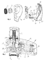
- Fig. 3 shows a perspective view into the interior of the cut housing 1, wherein the cut was guided both by the aluminum half-shell 5 and by the plastic half-shell 4. Through the cut only half of the union nut 3, a union nut 3 bearing fitting 7 and an opening 8 for the control knob 2 can be seen.
- a heat-conducting element 9 has direct contact with the connection piece 7 and ends in the figure to the right in an end piece 10, on which a thermogenerator 11 is arranged. If the thermostat is connected to a radiator, not shown here, the connecting piece 7 is heated by the heat of the heating water flowing to the radiator, and the end piece 10 of the heat-conducting element 9 is also heated by the peripheral contact between the connecting piece 7 and the heat-conducting element 9. Thus, the tail 10 for the thermogenerator 11 acts as a heat source.
- a cooling block 12 made of aluminum in contact with the thermoelectric generator 11.
- the cooling block 12 in turn is in direct thermal contact with an integral to the aluminum half-shell 5deblockpodest 14, so that the aluminum half-shell 5 and the cooling block 4 in common form the heat sink for the thermogenerator.
- the entire aluminum half shell 5 with its front wall 19 and the side walls 20 serves as a cooling wall element in the sense of the claims.
- thermoelectric voltage is generated in the thermogenerator 11 by means of the Seebeck effect, which is tapped via pick-off lines 13.
- the tapped voltage can directly or via a voltage amplifier for operating a motor, not shown, and / or for charging a battery 16 (see Fig. 5 ) are used.
- at least one additional energy harvester eg a solar cell unit, may additionally be provided.
- Fig. 4 shows the previously described elements of the thermostat in an exploded view, namely the aluminum half-shell 5, the cooling block 12, the thermoelectric generator 11 with its pick-up lines 13, the heat-conducting element 9 with its end 10, the plastic half-shell 4, the connector 7 and the Union nut 3.
- the aluminum half-shell 5 faces away from the radiator in a thermostat connected to a radiator and is constantly flowing around it by the convection of the surrounding air.
- the aluminum half-shell 5 is largely kept at ambient temperature by this flow.
- By belonging to the aluminum half-shell 5 and incorporated in the front wall 19doiblockpodest 14 and thus given direct contact with the cooling block 12 latter is also indirectly cooled by the flowing past the aluminum half-shell 5 ambient air effectively, so that a sufficient temperature gradient between the tail 10 of the heat-conducting element 9 and the cooling block 12 can be constructed, which is utilized by the thermal generator 11.
- the aluminum half-shell 5 offers in the given form on the one hand a large surface and on the other hand little flow resistance, so that an optimized heat absorption is ensured by the passing air.
- the front wall - in this case the edge areas are excluded to the side walls 20 - no or at most a very small curvature.
- the radius of curvature is about 165 mm
- Fig. 5 shows a supplemented to further elements construction of the housing interior of the thermostat in a section corresponding to the in Fig. 3 ,
- the thermal generator 11 is arranged between the end piece 10 of the heat-conducting element 9 and the cooling block 12.
- a circuit board 15 By means of a circuit board 15 the necessary electronics is provided to the thermostat.
- a lithium-ion accumulator 16 which can be charged by means of the voltage supplied by the thermal generator 11 voltage.
- an unillustrated motor is operated, with which the rotational position of a screw 17 can be changed.
- the screw 17 adjusted via a thread 21 in the drawing vertical position of a coupling element 18, which in turn determines the position of a valve, not shown here, with which the flow rate of heating water is controlled in a heating supply.
- the worm 17 thus acts as a valve guide element.
- a basic position of the worm 17 is predetermined via a plunger 19.
Landscapes
- Engineering & Computer Science (AREA)
- Physics & Mathematics (AREA)
- Automation & Control Theory (AREA)
- General Physics & Mathematics (AREA)
- Thermal Sciences (AREA)
- Chemical & Material Sciences (AREA)
- Combustion & Propulsion (AREA)
- Mechanical Engineering (AREA)
- General Engineering & Computer Science (AREA)
- Fluid Mechanics (AREA)
- Power Engineering (AREA)
- Cooling Or The Like Of Electrical Apparatus (AREA)
- Cooling Or The Like Of Semiconductors Or Solid State Devices (AREA)
- Devices That Are Associated With Refrigeration Equipment (AREA)
Applications Claiming Priority (1)
| Application Number | Priority Date | Filing Date | Title |
|---|---|---|---|
| DE102011053563A DE102011053563A1 (de) | 2011-09-13 | 2011-09-13 | Temperaturregelvorrichtung, insbesondere Thermostatvorrichtung |
Publications (4)
| Publication Number | Publication Date |
|---|---|
| EP2570881A2 true EP2570881A2 (fr) | 2013-03-20 |
| EP2570881A3 EP2570881A3 (fr) | 2014-04-30 |
| EP2570881B1 EP2570881B1 (fr) | 2017-03-01 |
| EP2570881B2 EP2570881B2 (fr) | 2020-02-19 |
Family
ID=47115258
Family Applications (1)
| Application Number | Title | Priority Date | Filing Date |
|---|---|---|---|
| EP12183313.1A Active EP2570881B2 (fr) | 2011-09-13 | 2012-09-06 | Dispositif de régulation de température, en particulier un dispositif thermostatique |
Country Status (2)
| Country | Link |
|---|---|
| EP (1) | EP2570881B2 (fr) |
| DE (1) | DE102011053563A1 (fr) |
Families Citing this family (1)
| Publication number | Priority date | Publication date | Assignee | Title |
|---|---|---|---|---|
| GB2575962A (en) * | 2018-06-04 | 2020-02-05 | E On Uk Plc | Thermostatic radiator valve controller |
Citations (3)
| Publication number | Priority date | Publication date | Assignee | Title |
|---|---|---|---|---|
| EP0717332A1 (fr) | 1994-12-12 | 1996-06-19 | Anthony Alford | Dispositif de contrÔle électrique pour un actionneur |
| DE102005025501A1 (de) | 2005-06-03 | 2006-12-07 | Danfoss A/S | Wärmetauscherventil-Steueraufsatz, insbesondere Heizkörperventil-Thermostataufsatz |
| DE102008031266A1 (de) | 2008-07-02 | 2010-01-14 | Eads Deutschland Gmbh | Thermogenerator |
Family Cites Families (5)
| Publication number | Priority date | Publication date | Assignee | Title |
|---|---|---|---|---|
| DE3414481A1 (de) | 1984-04-17 | 1985-10-24 | Hans Grohe Gmbh & Co Kg, 7622 Schiltach | Vorrichtung zur steuerung des durchflusses einer fluessigkeit |
| GB2216293B (en) | 1988-03-01 | 1992-02-19 | David Philip Reynolds | Valves |
| GB2278934B (en) | 1993-06-09 | 1996-11-06 | Anthony Alford | Electric control actuator |
| EP1602163B1 (fr) † | 2003-03-12 | 2014-12-03 | ABB Research Ltd. | Ensemble et procede pour l'alimentation en energie electrique sans fil d'un appareil de terrain dans une installation industrielle |
| DE102006014444A1 (de) | 2006-03-29 | 2007-10-04 | Abb Patent Gmbh | Einrichtung zur Energieversorgung von Feldgeräten |
-
2011
- 2011-09-13 DE DE102011053563A patent/DE102011053563A1/de not_active Withdrawn
-
2012
- 2012-09-06 EP EP12183313.1A patent/EP2570881B2/fr active Active
Patent Citations (4)
| Publication number | Priority date | Publication date | Assignee | Title |
|---|---|---|---|---|
| EP0717332A1 (fr) | 1994-12-12 | 1996-06-19 | Anthony Alford | Dispositif de contrÔle électrique pour un actionneur |
| DE102005025501A1 (de) | 2005-06-03 | 2006-12-07 | Danfoss A/S | Wärmetauscherventil-Steueraufsatz, insbesondere Heizkörperventil-Thermostataufsatz |
| DE102005025501C5 (de) | 2005-06-03 | 2010-10-21 | Danfoss A/S | Wärmetauscherventil-Steueraufsatz, insbesondere Heizkörperventil-Thermostataufsatz |
| DE102008031266A1 (de) | 2008-07-02 | 2010-01-14 | Eads Deutschland Gmbh | Thermogenerator |
Also Published As
| Publication number | Publication date |
|---|---|
| DE102011053563A1 (de) | 2013-03-14 |
| EP2570881A3 (fr) | 2014-04-30 |
| EP2570881B2 (fr) | 2020-02-19 |
| EP2570881B1 (fr) | 2017-03-01 |
Similar Documents
| Publication | Publication Date | Title |
|---|---|---|
| DE10128307B4 (de) | Klimaanlage | |
| DE69216844T2 (de) | Thermoelektrisches kühlsystem mit flexibelem wärmeleitelement | |
| EP2255605B1 (fr) | Dispositif de climatisation pour composants électroniques | |
| EP1729195B2 (fr) | Thermostat, en particulier pour radiateur pour chauffage domestique, comprenant un générateur thermoélectrique | |
| EP2676076A1 (fr) | Appareil de climatisation de local comprenant un appareil échangeur de chaleur liquide-air à éléments à effet peltier | |
| DE60317179T2 (de) | Beheiztes und gekühltes Lenkrad | |
| DE102011050742A1 (de) | Zusatzklimaanlage für ein Fahrzeug | |
| DE112018000025T5 (de) | Fahrzeugsitz und dessen Arbeitsprinzip sowie Fahrzeug | |
| EP3096587B1 (fr) | Dispositif de chauffage électrique | |
| DE2255736A1 (de) | Elektrische heizvorrichtung | |
| DE102021120776B4 (de) | Dachmodul zur Bildung eines Fahrzeugdachs mit einer Kühleinrichtung | |
| DE10352023A1 (de) | Klimatisierungsvorrichtung | |
| EP2772375A1 (fr) | Dispositif de chauffage électrique pour un véhicule automobile | |
| DE20007920U1 (de) | Belüftungsvorrichtung für ein Gehäuse | |
| DE112017007720T5 (de) | Kühlkörper | |
| EP2570881B1 (fr) | Dispositif de régulation de température, en particulier un dispositif thermostatique | |
| DE102019216925A1 (de) | Temperierungssystem für ein Kraftfahrzeug | |
| DE102010040107B4 (de) | Thermoelektrische Vorrichtung zum Erzeugen von elektrischer Energie | |
| DE102007017624B4 (de) | Thermoelektrische Temperiervorrichtung | |
| DE102019129815B4 (de) | Kühlvorrichtung für ein Endoskop oder Exoskop | |
| EP2894408B1 (fr) | Procédé de régulation de la température de pièces d'un bâtiment | |
| DE102006004414A1 (de) | Kühleinheit | |
| DE10137737B4 (de) | Optoelektronisches Gerät mit Thermostabilisierung | |
| EP3367769B1 (fr) | Dispositif de réception d'une électronique | |
| DE102008031584B4 (de) | Anordnung zum Verstellen eines Ventils |
Legal Events
| Date | Code | Title | Description |
|---|---|---|---|
| PUAI | Public reference made under article 153(3) epc to a published international application that has entered the european phase |
Free format text: ORIGINAL CODE: 0009012 |
|
| AK | Designated contracting states |
Kind code of ref document: A2 Designated state(s): AL AT BE BG CH CY CZ DE DK EE ES FI FR GB GR HR HU IE IS IT LI LT LU LV MC MK MT NL NO PL PT RO RS SE SI SK SM TR |
|
| AX | Request for extension of the european patent |
Extension state: BA ME |
|
| PUAL | Search report despatched |
Free format text: ORIGINAL CODE: 0009013 |
|
| AK | Designated contracting states |
Kind code of ref document: A3 Designated state(s): AL AT BE BG CH CY CZ DE DK EE ES FI FR GB GR HR HU IE IS IT LI LT LU LV MC MK MT NL NO PL PT RO RS SE SI SK SM TR |
|
| AX | Request for extension of the european patent |
Extension state: BA ME |
|
| RIC1 | Information provided on ipc code assigned before grant |
Ipc: G05D 23/02 20060101AFI20140327BHEP Ipc: H01L 35/00 20060101ALI20140327BHEP Ipc: G05D 23/19 20060101ALI20140327BHEP Ipc: F24D 19/10 20060101ALI20140327BHEP |
|
| 17P | Request for examination filed |
Effective date: 20141029 |
|
| RBV | Designated contracting states (corrected) |
Designated state(s): AL AT BE BG CH CY CZ DE DK EE ES FI FR GB GR HR HU IE IS IT LI LT LU LV MC MK MT NL NO PL PT RO RS SE SI SK SM TR |
|
| GRAP | Despatch of communication of intention to grant a patent |
Free format text: ORIGINAL CODE: EPIDOSNIGR1 |
|
| GRAJ | Information related to disapproval of communication of intention to grant by the applicant or resumption of examination proceedings by the epo deleted |
Free format text: ORIGINAL CODE: EPIDOSDIGR1 |
|
| INTG | Intention to grant announced |
Effective date: 20160725 |
|
| INTC | Intention to grant announced (deleted) | ||
| GRAP | Despatch of communication of intention to grant a patent |
Free format text: ORIGINAL CODE: EPIDOSNIGR1 |
|
| INTG | Intention to grant announced |
Effective date: 20160920 |
|
| STAA | Information on the status of an ep patent application or granted ep patent |
Free format text: STATUS: GRANT OF PATENT IS INTENDED |
|
| GRAS | Grant fee paid |
Free format text: ORIGINAL CODE: EPIDOSNIGR3 |
|
| GRAA | (expected) grant |
Free format text: ORIGINAL CODE: 0009210 |
|
| STAA | Information on the status of an ep patent application or granted ep patent |
Free format text: STATUS: THE PATENT HAS BEEN GRANTED |
|
| AK | Designated contracting states |
Kind code of ref document: B1 Designated state(s): AL AT BE BG CH CY CZ DE DK EE ES FI FR GB GR HR HU IE IS IT LI LT LU LV MC MK MT NL NO PL PT RO RS SE SI SK SM TR |
|
| REG | Reference to a national code |
Ref country code: GB Ref legal event code: FG4D Free format text: NOT ENGLISH |
|
| REG | Reference to a national code |
Ref country code: CH Ref legal event code: EP Ref country code: AT Ref legal event code: REF Ref document number: 872070 Country of ref document: AT Kind code of ref document: T Effective date: 20170315 |
|
| REG | Reference to a national code |
Ref country code: IE Ref legal event code: FG4D Free format text: LANGUAGE OF EP DOCUMENT: GERMAN |
|
| REG | Reference to a national code |
Ref country code: DE Ref legal event code: R096 Ref document number: 502012009623 Country of ref document: DE |
|
| REG | Reference to a national code |
Ref country code: NL Ref legal event code: MP Effective date: 20170301 |
|
| REG | Reference to a national code |
Ref country code: LT Ref legal event code: MG4D |
|
| PG25 | Lapsed in a contracting state [announced via postgrant information from national office to epo] |
Ref country code: LT Free format text: LAPSE BECAUSE OF FAILURE TO SUBMIT A TRANSLATION OF THE DESCRIPTION OR TO PAY THE FEE WITHIN THE PRESCRIBED TIME-LIMIT Effective date: 20170301 Ref country code: HR Free format text: LAPSE BECAUSE OF FAILURE TO SUBMIT A TRANSLATION OF THE DESCRIPTION OR TO PAY THE FEE WITHIN THE PRESCRIBED TIME-LIMIT Effective date: 20170301 Ref country code: NO Free format text: LAPSE BECAUSE OF FAILURE TO SUBMIT A TRANSLATION OF THE DESCRIPTION OR TO PAY THE FEE WITHIN THE PRESCRIBED TIME-LIMIT Effective date: 20170601 Ref country code: FI Free format text: LAPSE BECAUSE OF FAILURE TO SUBMIT A TRANSLATION OF THE DESCRIPTION OR TO PAY THE FEE WITHIN THE PRESCRIBED TIME-LIMIT Effective date: 20170301 Ref country code: GR Free format text: LAPSE BECAUSE OF FAILURE TO SUBMIT A TRANSLATION OF THE DESCRIPTION OR TO PAY THE FEE WITHIN THE PRESCRIBED TIME-LIMIT Effective date: 20170602 |
|
| REG | Reference to a national code |
Ref country code: DE Ref legal event code: R026 Ref document number: 502012009623 Country of ref document: DE |
|
| PLBI | Opposition filed |
Free format text: ORIGINAL CODE: 0009260 |
|
| PG25 | Lapsed in a contracting state [announced via postgrant information from national office to epo] |
Ref country code: BG Free format text: LAPSE BECAUSE OF FAILURE TO SUBMIT A TRANSLATION OF THE DESCRIPTION OR TO PAY THE FEE WITHIN THE PRESCRIBED TIME-LIMIT Effective date: 20170601 Ref country code: LV Free format text: LAPSE BECAUSE OF FAILURE TO SUBMIT A TRANSLATION OF THE DESCRIPTION OR TO PAY THE FEE WITHIN THE PRESCRIBED TIME-LIMIT Effective date: 20170301 Ref country code: SE Free format text: LAPSE BECAUSE OF FAILURE TO SUBMIT A TRANSLATION OF THE DESCRIPTION OR TO PAY THE FEE WITHIN THE PRESCRIBED TIME-LIMIT Effective date: 20170301 Ref country code: ES Free format text: LAPSE BECAUSE OF FAILURE TO SUBMIT A TRANSLATION OF THE DESCRIPTION OR TO PAY THE FEE WITHIN THE PRESCRIBED TIME-LIMIT Effective date: 20170301 Ref country code: RS Free format text: LAPSE BECAUSE OF FAILURE TO SUBMIT A TRANSLATION OF THE DESCRIPTION OR TO PAY THE FEE WITHIN THE PRESCRIBED TIME-LIMIT Effective date: 20170301 |
|
| REG | Reference to a national code |
Ref country code: FR Ref legal event code: PLFP Year of fee payment: 6 |
|
| 26 | Opposition filed |
Opponent name: PRECISION MOTORS DEUTSCHE MINEBEA GMBH Effective date: 20170821 |
|
| PG25 | Lapsed in a contracting state [announced via postgrant information from national office to epo] |
Ref country code: NL Free format text: LAPSE BECAUSE OF FAILURE TO SUBMIT A TRANSLATION OF THE DESCRIPTION OR TO PAY THE FEE WITHIN THE PRESCRIBED TIME-LIMIT Effective date: 20170301 |
|
| PG25 | Lapsed in a contracting state [announced via postgrant information from national office to epo] |
Ref country code: SK Free format text: LAPSE BECAUSE OF FAILURE TO SUBMIT A TRANSLATION OF THE DESCRIPTION OR TO PAY THE FEE WITHIN THE PRESCRIBED TIME-LIMIT Effective date: 20170301 Ref country code: IT Free format text: LAPSE BECAUSE OF FAILURE TO SUBMIT A TRANSLATION OF THE DESCRIPTION OR TO PAY THE FEE WITHIN THE PRESCRIBED TIME-LIMIT Effective date: 20170301 Ref country code: CZ Free format text: LAPSE BECAUSE OF FAILURE TO SUBMIT A TRANSLATION OF THE DESCRIPTION OR TO PAY THE FEE WITHIN THE PRESCRIBED TIME-LIMIT Effective date: 20170301 Ref country code: EE Free format text: LAPSE BECAUSE OF FAILURE TO SUBMIT A TRANSLATION OF THE DESCRIPTION OR TO PAY THE FEE WITHIN THE PRESCRIBED TIME-LIMIT Effective date: 20170301 Ref country code: RO Free format text: LAPSE BECAUSE OF FAILURE TO SUBMIT A TRANSLATION OF THE DESCRIPTION OR TO PAY THE FEE WITHIN THE PRESCRIBED TIME-LIMIT Effective date: 20170301 |
|
| PG25 | Lapsed in a contracting state [announced via postgrant information from national office to epo] |
Ref country code: IS Free format text: LAPSE BECAUSE OF FAILURE TO SUBMIT A TRANSLATION OF THE DESCRIPTION OR TO PAY THE FEE WITHIN THE PRESCRIBED TIME-LIMIT Effective date: 20170701 Ref country code: SM Free format text: LAPSE BECAUSE OF FAILURE TO SUBMIT A TRANSLATION OF THE DESCRIPTION OR TO PAY THE FEE WITHIN THE PRESCRIBED TIME-LIMIT Effective date: 20170301 Ref country code: PT Free format text: LAPSE BECAUSE OF FAILURE TO SUBMIT A TRANSLATION OF THE DESCRIPTION OR TO PAY THE FEE WITHIN THE PRESCRIBED TIME-LIMIT Effective date: 20170703 Ref country code: PL Free format text: LAPSE BECAUSE OF FAILURE TO SUBMIT A TRANSLATION OF THE DESCRIPTION OR TO PAY THE FEE WITHIN THE PRESCRIBED TIME-LIMIT Effective date: 20170301 |
|
| PLAX | Notice of opposition and request to file observation + time limit sent |
Free format text: ORIGINAL CODE: EPIDOSNOBS2 |
|
| PG25 | Lapsed in a contracting state [announced via postgrant information from national office to epo] |
Ref country code: DK Free format text: LAPSE BECAUSE OF FAILURE TO SUBMIT A TRANSLATION OF THE DESCRIPTION OR TO PAY THE FEE WITHIN THE PRESCRIBED TIME-LIMIT Effective date: 20170301 |
|
| PG25 | Lapsed in a contracting state [announced via postgrant information from national office to epo] |
Ref country code: SI Free format text: LAPSE BECAUSE OF FAILURE TO SUBMIT A TRANSLATION OF THE DESCRIPTION OR TO PAY THE FEE WITHIN THE PRESCRIBED TIME-LIMIT Effective date: 20170301 |
|
| PLBB | Reply of patent proprietor to notice(s) of opposition received |
Free format text: ORIGINAL CODE: EPIDOSNOBS3 |
|
| REG | Reference to a national code |
Ref country code: CH Ref legal event code: PL |
|
| GBPC | Gb: european patent ceased through non-payment of renewal fee |
Effective date: 20170906 |
|
| PG25 | Lapsed in a contracting state [announced via postgrant information from national office to epo] |
Ref country code: MC Free format text: LAPSE BECAUSE OF FAILURE TO SUBMIT A TRANSLATION OF THE DESCRIPTION OR TO PAY THE FEE WITHIN THE PRESCRIBED TIME-LIMIT Effective date: 20170301 |
|
| REG | Reference to a national code |
Ref country code: IE Ref legal event code: MM4A |
|
| REG | Reference to a national code |
Ref country code: BE Ref legal event code: MM Effective date: 20170930 |
|
| PG25 | Lapsed in a contracting state [announced via postgrant information from national office to epo] |
Ref country code: LU Free format text: LAPSE BECAUSE OF NON-PAYMENT OF DUE FEES Effective date: 20170906 |
|
| PG25 | Lapsed in a contracting state [announced via postgrant information from national office to epo] |
Ref country code: LI Free format text: LAPSE BECAUSE OF NON-PAYMENT OF DUE FEES Effective date: 20170930 Ref country code: GB Free format text: LAPSE BECAUSE OF NON-PAYMENT OF DUE FEES Effective date: 20170906 Ref country code: IE Free format text: LAPSE BECAUSE OF NON-PAYMENT OF DUE FEES Effective date: 20170906 Ref country code: CH Free format text: LAPSE BECAUSE OF NON-PAYMENT OF DUE FEES Effective date: 20170930 |
|
| PG25 | Lapsed in a contracting state [announced via postgrant information from national office to epo] |
Ref country code: BE Free format text: LAPSE BECAUSE OF NON-PAYMENT OF DUE FEES Effective date: 20170930 |
|
| REG | Reference to a national code |
Ref country code: FR Ref legal event code: PLFP Year of fee payment: 7 |
|
| PG25 | Lapsed in a contracting state [announced via postgrant information from national office to epo] |
Ref country code: MT Free format text: LAPSE BECAUSE OF FAILURE TO SUBMIT A TRANSLATION OF THE DESCRIPTION OR TO PAY THE FEE WITHIN THE PRESCRIBED TIME-LIMIT Effective date: 20170301 |
|
| PG25 | Lapsed in a contracting state [announced via postgrant information from national office to epo] |
Ref country code: HU Free format text: LAPSE BECAUSE OF FAILURE TO SUBMIT A TRANSLATION OF THE DESCRIPTION OR TO PAY THE FEE WITHIN THE PRESCRIBED TIME-LIMIT; INVALID AB INITIO Effective date: 20120906 |
|
| PG25 | Lapsed in a contracting state [announced via postgrant information from national office to epo] |
Ref country code: CY Free format text: LAPSE BECAUSE OF NON-PAYMENT OF DUE FEES Effective date: 20170301 |
|
| PG25 | Lapsed in a contracting state [announced via postgrant information from national office to epo] |
Ref country code: MK Free format text: LAPSE BECAUSE OF FAILURE TO SUBMIT A TRANSLATION OF THE DESCRIPTION OR TO PAY THE FEE WITHIN THE PRESCRIBED TIME-LIMIT Effective date: 20170301 |
|
| PUAH | Patent maintained in amended form |
Free format text: ORIGINAL CODE: 0009272 |
|
| STAA | Information on the status of an ep patent application or granted ep patent |
Free format text: STATUS: PATENT MAINTAINED AS AMENDED |
|
| 27A | Patent maintained in amended form |
Effective date: 20200219 |
|
| AK | Designated contracting states |
Kind code of ref document: B2 Designated state(s): AL AT BE BG CH CY CZ DE DK EE ES FI FR GB GR HR HU IE IS IT LI LT LU LV MC MK MT NL NO PL PT RO RS SE SI SK SM TR |
|
| REG | Reference to a national code |
Ref country code: DE Ref legal event code: R102 Ref document number: 502012009623 Country of ref document: DE |
|
| PG25 | Lapsed in a contracting state [announced via postgrant information from national office to epo] |
Ref country code: TR Free format text: LAPSE BECAUSE OF FAILURE TO SUBMIT A TRANSLATION OF THE DESCRIPTION OR TO PAY THE FEE WITHIN THE PRESCRIBED TIME-LIMIT Effective date: 20170301 |
|
| PG25 | Lapsed in a contracting state [announced via postgrant information from national office to epo] |
Ref country code: AL Free format text: LAPSE BECAUSE OF FAILURE TO SUBMIT A TRANSLATION OF THE DESCRIPTION OR TO PAY THE FEE WITHIN THE PRESCRIBED TIME-LIMIT Effective date: 20170301 |
|
| PGFP | Annual fee paid to national office [announced via postgrant information from national office to epo] |
Ref country code: DE Payment date: 20250930 Year of fee payment: 14 |
|
| PGFP | Annual fee paid to national office [announced via postgrant information from national office to epo] |
Ref country code: FR Payment date: 20250926 Year of fee payment: 14 Ref country code: AT Payment date: 20250918 Year of fee payment: 14 |