EP2572968A2 - Motocyclette avec structure de feu arrière - Google Patents
Motocyclette avec structure de feu arrière Download PDFInfo
- Publication number
- EP2572968A2 EP2572968A2 EP12197772A EP12197772A EP2572968A2 EP 2572968 A2 EP2572968 A2 EP 2572968A2 EP 12197772 A EP12197772 A EP 12197772A EP 12197772 A EP12197772 A EP 12197772A EP 2572968 A2 EP2572968 A2 EP 2572968A2
- Authority
- EP
- European Patent Office
- Prior art keywords
- motorcycle
- mudguard
- translucent member
- cover
- angle
- Prior art date
- Legal status (The legal status is an assumption and is not a legal conclusion. Google has not performed a legal analysis and makes no representation as to the accuracy of the status listed.)
- Granted
Links
Images


Classifications
-
- B—PERFORMING OPERATIONS; TRANSPORTING
- B62—LAND VEHICLES FOR TRAVELLING OTHERWISE THAN ON RAILS
- B62J—CYCLE SADDLES OR SEATS; AUXILIARY DEVICES OR ACCESSORIES SPECIALLY ADAPTED TO CYCLES AND NOT OTHERWISE PROVIDED FOR, e.g. ARTICLE CARRIERS OR CYCLE PROTECTORS
- B62J6/00—Arrangement of optical signalling or lighting devices on cycles; Mounting or supporting thereof; Circuits therefor
- B62J6/04—Rear lights
-
- B—PERFORMING OPERATIONS; TRANSPORTING
- B62—LAND VEHICLES FOR TRAVELLING OTHERWISE THAN ON RAILS
- B62J—CYCLE SADDLES OR SEATS; AUXILIARY DEVICES OR ACCESSORIES SPECIALLY ADAPTED TO CYCLES AND NOT OTHERWISE PROVIDED FOR, e.g. ARTICLE CARRIERS OR CYCLE PROTECTORS
- B62J15/00—Mud-guards for wheels
Definitions
- the present invention relates to a motorcycle, in particular, a motorcycle including a tail lamp arranged above a rear wheel and at least having a surface of a translucent member directed obliquely downwardly and rearwardly.
- a surface of a translucent member of a tail lamp is directed obliquely downwardly and rearwardly.
- JP 4005377 B discloses a motorcycle including such a tail lamp.
- the motorcycle includes a rear fender which is located below a tail lamp and to which a license plate can be attached.
- the rear fender is inclined obliquely downwardly and rearwardly in a side view.
- a mudguard of the motorcycle is simply shaped to extend obliquely downwardly.
- a motorcycle according to the present invention includes: a frame extending in a front-rear direction of a vehicle body; a rear wheel supported to be swingable with respect to the frame; a right cover and a left cover that cover at least a right side and a left side of the frame located higher up than the rear wheel; a tail lamp which is arranged higher up than the rear wheel and connected to a rear portion of each of the right cover and the left cover, the tail lamp at least having a surface of a translucent member directed obliquely downwardly and rearwardly; and a mudguard having a first portion extending obliquely downwardly and rearwardly from a front side of the surface of the translucent member in the front-rear direction of the motorcycle to cover the surface of the translucent member in a bottom view, and a second portion extending downwardly from a rear portion of the first portion at an angle with respect to a ground surface that is at least larger than a corresponding angle of the first portion, the second
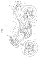
- FIG. 1 is a side view of a motorcycle 1 according to this embodiment.
- the motorcycle 1 includes an engine 3 mounted on a frame 2 extending in a front-rear direction of a vehicle body, a fuel tank 4, a seat 5, a front wheel 7, a rear wheel 8, and a swing arm 9 that rotatably supports the rear wheel 8.
- the swing arm 9 is pivotably attached to a pivot 10 of the frame 2.
- the rear wheel 8 is supported to be swingable about the pivot 10 with respect to the frame 2.
- a sports-type motorcycle is illustrated as the motorcycle 1 in FIG. 1 , this is merely illustrative, and it is not intended to limit the type of motorcycle 1.
- components that are not directly related to the present invention, such as brake pads, hydraulic piping, and electrical wiring, are not illustrated.
- right and left covers 11 that cover the right and left sides of the frame 2 and are located above the rear wheel 8
- a tail lamp 12 arranged above the rear wheel 8 and connected to the rear portions of the covers 11,
- a rear fender 13 that covers the rear wheel 8 from above and is connected to the covers 11 below the frame 2, and a mudguard 14.
- Various safety components such as directional indicators 15, a license plate light 16, and a reflection panel 17 are attached to the mudguard 14.
- Reference numeral 18 denotes a license plate attachment portion to which a license plate is capable of being attached (not shown).
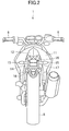
- FIG. 2 is a back view of the motorcycle 1 according to this embodiment.
- the positional relationship of handlebars 6, the rear wheel 8, the covers 11, the tail lamp 12, the mudguard 14, the directional indicators 15, the license plate light 16, the reflection panel 17, and the license plate attachment portion 18 is clearly illustrated.
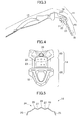
- FIG. 3 is a side view of the rear fender 13 and the mudguard 14.
- the rear fender 13 and the mudguard 14 are formed integrally with each other by molding of a synthetic resin such as polypropylene.
- the rear fender 13 and the mudguard 14 may be fabricated separately to be connected together by a known method such as screwing, or to be kept separated from each other.
- the material of the rear fender 13 and the mudguard 14 is not particularly limited.
- the mudguard 14 is divided into a first portion 19 and a second portion 20. This dividing does not immediately mean that the mudguard 14 is physically divided into the first portion 19 and the second portion 20.
- the dividing means that the mudguard 14 is divided into portions in accordance with their respective functions for convenience. It is a matter of course that the first portion 19 and the second portion 20 may be fabricated separately and then joined together by a known method such as screwing or bonding. As illustrated in the figure, the first portion 19 extends in an inclined manner obliquely downwardly and rearwardly with respect to the motorcycle 1.
- the second portion 20 is connected to the rear portion of the first portion 19.
- the second portion 20 extends downwardly at an inclination angle with respect to the ground surface that is larger than the inclination angle of the first portion 19 with respect to the ground surface.
- a hole which serves as a directional indicator attachment portion 21 is formed in each side surface of the mudguard 14.
- the license plate attachment portion 18, a license plate light attachment portion 22, and a reflection panel attachment portion 23 are provided in the second portion 20.
- FIG. 4 is a back view of the mudguard 14.
- the first portion 19 has a concave-convex shape portion 24 for increasing the rigidity on its upper surface.
- the license plate light attachment portion 22 the reflection panel attachment portion 23, and the license plate attachment portion 18 are provided in this order from above.
- those elements have high visibility from the back side of the motorcycle 1. This provides excellent visibility of a reflection panel and the license plate from the rear side thereof when they are attached. This is because the inclination angle of the second portion 20 with respect to the ground surface is relatively large as described later.
- the license plate light attachment portion 22 is provided with holes for attachment of the license plate light 16 and for passage of wires.
- the reflection panel attachment portion 23 is provided with holes in an asymmetrical arrangement in the right-left direction, which prevents upside-down attachment of the reflection panel 17.
- FIG. 5 is a cross-sectional view of the first portion 19 taken along the plane A-A of FIG. 3 .
- the first portion 19 has a U-shaped cross section opened substantially downwardly.
- Side wall portions 25 extending downwardly are provided at both ends of the first portion 19 in the right-left direction.
- the concave-convex shape portion 24 is provided on the upper surface of the first portion 19.
- the concave-convex shape portion 24 includes three convex portions 26 that project upwardly and two concave portions 27 that are depressed downwardly.
- the side wall portions 25 and the concave-convex shape portion 24 both serve to increase the rigidity of the first portion 19.
- the numbers of concave portions and convex portions of the concave-convex shape portion 24 are not limited to those used in this embodiment. Any cross section with two or more projections, that is, two or more convex portions 26 and one or more concave portions 27, in the right-left direction of the motorcycle 1 can provide an increased rigidity compared to a simple cross section in the shape of an inverted letter V.
- the first portion 19 and the second portion 20 of the mudguard 14 are different in inclination angle with respect to the ground surface.
- the inclination angle may be defined in any one of a plurality of methods described below.
- FIG. 6 illustrates a first method for defining the inclination angle.
- the inclination angle is defined as an angle between a plane or a straight line that is tangent to the upper surface of the mudguard 14 and the ground surface.
- a first tangent plane 28 and a second tangent plane 29 are illustrated.
- the first tangent plane 28 is defined to pass through points 30 and 31 of the mudguard 14 which project upwardly.
- the second tangent plane 29 is defined to pass through points 31 and 32 of the mudguard 14 which project upwardly.
- tangent planes or lines In defining tangent planes or lines, local features provided for specific purposes, such as the projections in the concave-convex shape portion 24 for increasing the rigidity, are ignored for convenience.
- the position at which the angle of the tangent plane with respect to the ground surface changes that is, the point 31 in this example, is defined as the boundary between the first portion 19 and the second portion 20.
- An angle ⁇ of the first tangent plane 28 with respect to the ground surface is defined as the inclination angle of the first portion 19 with respect to the ground surface.
- An angle ⁇ of the second tangent plane 29 with respect to the ground surface is defined as the inclination angle of the second portion 20 with respect to the ground surface.
- ⁇ is less than ⁇ .
- ⁇ is less than 45° and ⁇ is more than 45°.
- the first portion 19 effectively blocks a mud splash toward the vehicle body, particularly toward the tail lamp 12, and the second portion 20 provides excellent visibility of the license plate when it is attached thereto.
- the first portion 19 is larger in the front-rear direction than in the up-down direction, and the second portion 20 is smaller in the front-rear direction than in the up-down direction.
- the inclination angle is defined as an angle of a tangent plane with respect to the ground surface in the above description, the inclination angle may alternatively be defined as an angle of a tangent line in any cross section in the front-rear direction of the motorcycle 1, for example, a cross section along the center line of the motorcycle 1, with respect to the ground surface.
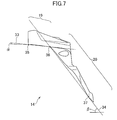
- FIG. 7 illustrates a second method for defining the inclination angle.
- the inclination angle is defined as an angle between a plane or a straight line that is tangent to the lower surface of the mudguard 14 and the ground surface. That is, as illustrated in FIG. 7 , the inclination angle ⁇ of the first portion 19 is defined by a first tangent plane 33 which passes through points 35 and 36.
- the inclination angle ⁇ of the second portion 20 is defined by a second tangent plane 34 which passes through points 36 and 37.
- the point 36 is defined as the boundary between the first portion 19 and the second portion 20.
- ⁇ is less than ⁇ .
- ⁇ is less than 45° and ⁇ is more than 45°.
- a tangent line in any cross section in the front-rear direction of the motorcycle 1 may be used to define the inclination angle with respect to the ground surface.
- FIG. 8 illustrates a third method for defining the inclination angle.
- a portion of the mudguard 14 from its front end to the license plate light attachment portion 22 is defined as the first portion 19, and a portion of the mudguard 14 from the license plate light attachment portion 22 to the rear end of the mudguard 14 is defined as the second portion 20. That is, the license plate light 16 is arranged at the boundary between the first portion 19 and the second portion 20.
- the inclination angle of the first portion 19 is defined as the angle ⁇ of a first plane 38, which passes through a front-end uppermost point 40 of the first portion 19 and a center point 41 of the license plate light attachment portion 22, with respect to the ground surface.
- the inclination angle of the second portion 20 is defined as the angle ⁇ of a second plane 39, which passes through the center point 41 of the license plate light attachment portion 22 and a rear-end lowermost point 42 of the second portion 20, with respect to the ground surface.
- the relationship between the angles ⁇ and ⁇ is the same as that in the case of the first method. That is, ⁇ is less than ⁇ . Preferably, ⁇ is less than 45° and ⁇ is more than 45°.
- a straight line in any cross section in the front-rear direction of the motorcycle 1 may be used to define the inclination angle with respect to the ground surface. While the first plane 38 and the second plane 39 are defined to pass through the center point 41 of the license plate light attachment portion 22, the first plane 38 and the second plane 39 may instead be defined using the uppermost or lowermost point of the license plate light attachment portion 22.
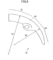
- FIG. 9 illustrates a first modification of the mudguard 14.
- the first portion 19 and the second portion 20 of the mudguard 14 are gently curved downwardly in a side view.
- ⁇ 1 is less than ⁇ 2.
- the boundary between the first portion 19 and the second portion 20 is defined as an inflection point 43 at which the curvature of the mudguard 14 changes.
- the respective inclination angles of the first portion 19 and the second portion 20 with respect to the ground surface may be defined as follows, for example.
- the inclination angle may be defined as an angle between the ground surface and a plane or a straight line that passes through the front-end uppermost point on the upper surface of the first portion 19 and the inflection point 43.
- the inclination angle may be defined as an angle between the ground surface and a plane or a straight line that passes through the inflection point 43 and the rear-end lowermost point on the upper surface of the second portion 20.
- respective average inclination angles of the first portion 19 and the second portion 20 may be employed.
- FIG. 10 illustrates a second modification of the mudguard 14.
- a third portion 44 is provided between the first portion 19 and the second portion 20.
- An inclination angle ⁇ of the third portion 44 is different from each of the inclination angle ⁇ of the first portion 19 and the inclination angle ⁇ of the second portion 20.
- the inclination angles may be defined in accordance with any one of the methods described above. Also in this case, the relationship between the angles ⁇ and ⁇ is the same as those in the case of the first method. That is, ⁇ is less than ⁇ . Preferably, ⁇ is less than 45° and ⁇ is more than 45°.
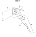
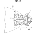
- FIGS. 11 and 12 are a side view and a top view, respectively, illustrating the positional relationship between the tail lamp 12 and the mudguard 14.
- the external shape of the covers 11 is indicated by the broken line.
- the tail lamp 12 has a surface of a translucent member 45 directed obliquely downwardly and rearwardly.
- the surface of the translucent member 45 is preferably a lens surface that diffuses a light beam emitted from a light source such as a light emitting diode or a bulb housed in the tail lamp 12, and is molded from a translucent resin such as polycarbonate or polymethyl methacrylate.
- a lens member may be separately provided in the tail lamp 12, in which case the surface of the translucent member 45 may simply be a transparent cover of any material or in any color.
- the first portion 19 of the mudguard 14 extends obliquely downwardly and rearwardly from the front end of the surface of the translucent member 45 in the front-rear direction of the motorcycle. This allows the first portion 19 to be arranged close to the surface of the translucent member 45. As can be seen from FIG. 12 , the first portion 19 is arranged to cover the surface of the translucent member 45 from below. That is, the first portion 19 is larger in dimension in the right-left direction of themotorcycle than the surface of the translucent member 45 at the front portion of the surface of the translucent member 45 in the front-rear direction of the motorcycle.
- the first portion 19 is also larger in dimension in the right-left direction of the motorcycle than the surface of the translucent member 45 at any location in the front-rear direction of the motorcycle.
- the first portion 19 extends further rearward than the surface of the translucent member 45. Therefore, the second portion 20 is located further rearward than the rear end of the surface of the translucent member 45.
- the thus configured first portion 19 effectively blocks a mud splash toward the vehicle body of the motorcycle 1, particularly toward the surface of the translucent member 45 of the tail lamp 12.
- the covers 11 are shaped to cover the surface of the translucent member 45 from above and to become smaller in dimension in the right-left direction of the motorcycle, extending rearwardly in a plan view. This prevents entry of external light into the tail lamp 12, and makes the rear portion of the vehicle body of the motorcycle 1 compact.
- the first portion 19 is arranged to extend from the front end of the surface of the translucent member 45 in the front-rear direction of the motorcycle in order to arrange the first portion 19 as close as possible to the surface of the translucent member 45.
- a separation gap 46 may be provided between the surface of the translucent member 45 and the first portion 19 as illustrated in FIG. 13 .
- Some kind of plate may be inserted into the separation gap 46, or the covers 11 may be extended from both the right and left sides to occupy the gap 46.
- the first portion 19 is configured to extend from a location forward of the surface of the translucent member 45 in the front-rear direction of the motorcycle.
- the license plate attachment portion 18 of the second portion 20 is preferably provided rearwardly of the rear end of the rear wheel 8 as illustrated in FIG. 1 . With such a configuration, mud splashed by the rear wheel 8 is less likely to adhere to the surface of the license plate (not shown). For ease of understanding, the position corresponding to the rear end of the rear wheel 8 is indicated by a broken line 47 in FIG. 1 .
- the angle of each of the first portion 19 and the second portion 20 may be defined as an angle of the upper surface of each portion with respect to the ground surface.
- the angle of each of the first portion 19 and the second portion 20 may be defined as an angle of the lower surface of each portion with respect to the ground surface in a side view.
- the angle of each of the first portion 19 and the second portion 20 may be defined as an angle of each portion in its cross section in the front-rear direction of the motorcycle with respect to the ground surface. Irrespective of the method employed to define the angle, it is possible to sufficiently block a mud splash toward the vehicle body by making the angle of the second portion 20 larger than the angle of the first portion 19.
- the license plate light 16 is arranged at the boundary between the first portion 19 and the second portion 20. With this configuration, the visibility of the license plate is improved by irradiation from the license plate light 16.
- the boundary between the first portion 19 and the second portion 20 is defined as a position at which the angle of the mudguard 14 with respect to the ground surface changes or as a position at which the curvature of the mudguard 14 changes.
- the first portion 19 mainly provides a mud blocking effect
- the second portion 20 mainly provides excellent visibility of the license plate. This configuration achieves functional separation, and also makes the mudguard 14 compact.
- the third portion 44 may be provided between the first portion 19 and the second portion 20, and the angle of the third portion 44 with respect to the ground surface is different from each of the corresponding angles of the first portion 19 and the second portion 20.
- the mudguard 14 extends rearwardly from the front end of the surface of the translucent member 45 in the front-rear direction of the motorcycle. With this configuration, the distance between the surface of the translucent member 45 and the first portion 19 is reduced.
- the first portion 19 includes the side wall portion 25 extending downwardly at each of both ends of the first portion 19 in the right-left direction of the motorcycle. With this configuration, the rigidity of the first portion 19 is enhanced.
- the first portion 19 has the concave-convex shape portion 24 on its upper surface. With this configuration, the rigidity of the first portion 19 is enhanced.
- the license plate attachment portion 18 is provided rearward of the rear end of the rear wheel 8. This configuration makes it less likely that mud will adhere to the surface of the license plate.
- the motorcycle 1 further includes the rear fender 13 that is connected to the right and left covers 11 to cover the rear wheel 8 from above, and the mudguard 14 and the rear fender 13 are formed integrally with each other.
- This configuration allows reduction in number of components, thereby facilitating assembly.
- the right and left covers 11 cover the surface of the translucent member 45 from above in a plan view. This configuration prevents entry of external light into the tail lamp 12.
- the light source of the tail lamp 12 is a light emitting diode. This realizes low power consumption.
- the rear portions of the right and left covers 11 become smaller in dimension in the right-left direction of the motorcycle, extending rearwardly in a plan view. This configuration makes the rear portion of the vehicle body compact.
- the first portion 19 is larger in dimension in the front-rear direction than in the up-down direction in a side view. This configuration reduces the distance between the first portion 19 and the surface of the translucent member 45.
- the second portion 20 is smaller in dimension in the front-rear direction than in the up-down direction in a side view. This configuration provides good visibility of a license plate from the rear side thereof.
- the second portion 20 is located further rearward than the rear end of the surface of the translucent member 45 in a side view. With this configuration, the surface of the translucent member 45 is covered by the first portion 19.
- the mudguard 14 is larger than the surface of the translucent member 45 in dimension in the right-left direction of the motorcycle at a location corresponding to the front portion of the surface of the translucent member 45 in the front-rear direction of the motorcycle.
- the first portion 19 is larger than the surface of the translucent member 45 in dimension in the right-left direction of the motorcycle at any location in the front-rear direction of the motorcycle. Withthisconfiguration, the surface of the translucent member 45 is covered by the first portion 19.
- a motorcycle comprises:
- the angle of each of the first portion and the second portion is defined either as an angle of an upper surface of each of the first portion and the second portion with respect to the ground surface or as an angle of a lower surface of each of the first portion and the second portion with respect to the ground surface in a side view or as an angle of each of the first portion and the second portion with respect to the ground surface in a cross section in the front-rear direction of the motorcycle.
- a license plate light is arranged at a boundary between the first portion and the second portion.
- a boundary between the first portion and the second portion is defined as a position at which an angle of the mudguard with respect to the ground surface changes or as a position at which a curvature of the mudguard changes.
- a third portion is provided between the first portion and the second portion, and an angle of the third portion with respect to the ground surface is different from each of the corresponding angles of the first portion and the second portion.
- the mudguard extends rearwardly from a front end of the surface of the translucent member in the front-rear direction of the motorcycle.
- the first portion comprises a side wall portion extending downwardly at each of both ends of the first portion in a right-left direction of the motorcycle (1).
- the first portion (19) has a concave-convex shape portion (24) on its upper surface.
- the license plate attachment portion is provided rearwardly of a rear end of the rear wheel.
- the motorcycle according to the first aspect claim 1 further comprises a rear fender that is connected to the right cover and the left cover to cover the rear wheel from above, wherein the mudguard and the rear fender are formed integrally with each other.
- the right cover and the left cover cover the surface of the translucent member from above in a plan view.
- a light source of the tail lamp comprises a light emitting diode.
- the rear portion of each of the right cover and the left cover becomes smaller in dimension in a right-left direction of the motorcycle, extending rearwardly in a plan view.
- the first portion is larger in dimension in the front-rear direction than in an up-down direction in a side view.
- the secondportion is smaller in dimension in the front-rear direction than in an up-down direction in a side view.
- the second portion is located further rearward than a rear end of the surface of the translucent member in a side view.
- the mudguard is larger than the surface of the translucent member in dimension in a right-left direction of the motorcycle at a location corresponding to a front portion of the surface of the translucent member in the front-rear direction of the motorcycle.
- the first portion is larger than the surface of the translucent member in dimension in a right-left direction of the motorcycle at any location in the front-rear direction of the motorcycle.
Landscapes
- Engineering & Computer Science (AREA)
- Mechanical Engineering (AREA)
- Lighting Device Outwards From Vehicle And Optical Signal (AREA)
- Non-Portable Lighting Devices Or Systems Thereof (AREA)
- Tires In General (AREA)
Applications Claiming Priority (2)
| Application Number | Priority Date | Filing Date | Title |
|---|---|---|---|
| JP2009062509A JP2010215054A (ja) | 2009-03-16 | 2009-03-16 | 自動二輪車 |
| EP09179206A EP2230163A1 (fr) | 2009-03-16 | 2009-12-15 | Motocyclette avec structure de feu arrière |
Related Parent Applications (2)
| Application Number | Title | Priority Date | Filing Date |
|---|---|---|---|
| EP09179206A Division EP2230163A1 (fr) | 2009-03-16 | 2009-12-15 | Motocyclette avec structure de feu arrière |
| EP09179206.9 Division | 2009-12-15 |
Publications (3)
| Publication Number | Publication Date |
|---|---|
| EP2572968A2 true EP2572968A2 (fr) | 2013-03-27 |
| EP2572968A3 EP2572968A3 (fr) | 2013-04-17 |
| EP2572968B1 EP2572968B1 (fr) | 2017-08-09 |
Family
ID=41557429
Family Applications (2)
| Application Number | Title | Priority Date | Filing Date |
|---|---|---|---|
| EP12197772.2A Active EP2572968B1 (fr) | 2009-03-16 | 2009-12-15 | Motocyclette avec structure de feu arrière |
| EP09179206A Withdrawn EP2230163A1 (fr) | 2009-03-16 | 2009-12-15 | Motocyclette avec structure de feu arrière |
Family Applications After (1)
| Application Number | Title | Priority Date | Filing Date |
|---|---|---|---|
| EP09179206A Withdrawn EP2230163A1 (fr) | 2009-03-16 | 2009-12-15 | Motocyclette avec structure de feu arrière |
Country Status (4)
| Country | Link |
|---|---|
| EP (2) | EP2572968B1 (fr) |
| JP (1) | JP2010215054A (fr) |
| CN (1) | CN101837813B (fr) |
| BR (1) | BRPI1002210B1 (fr) |
Families Citing this family (3)
| Publication number | Priority date | Publication date | Assignee | Title |
|---|---|---|---|---|
| JP6066344B2 (ja) * | 2014-08-29 | 2017-01-25 | 本田技研工業株式会社 | 自動二輪車の後部構造 |
| JP7216743B2 (ja) * | 2018-12-21 | 2023-02-01 | カワサキモータース株式会社 | 鞍乗型車両 |
| CN111003086A (zh) * | 2019-12-30 | 2020-04-14 | 江门市大长江集团有限公司 | 一种摩托车的后挡泥板组件及摩托车 |
Citations (1)
| Publication number | Priority date | Publication date | Assignee | Title |
|---|---|---|---|---|
| JPH045377B2 (fr) | 1984-12-26 | 1992-01-31 |
Family Cites Families (4)
| Publication number | Priority date | Publication date | Assignee | Title |
|---|---|---|---|---|
| JPH0414312Y2 (fr) * | 1986-05-27 | 1992-03-31 | ||
| JP4130016B2 (ja) * | 1998-08-17 | 2008-08-06 | 本田技研工業株式会社 | 自動2輪車のリヤフェンダ装置 |
| US7234559B2 (en) * | 2003-09-09 | 2007-06-26 | Honda Motor Co., Ltd. | Rear fender and related support structure for a motorcycle, and motorcycle including same |
| JP5017001B2 (ja) | 2007-07-05 | 2012-09-05 | 本田技研工業株式会社 | 自動二輪車のリヤフェンダー |
-
2009
- 2009-03-16 JP JP2009062509A patent/JP2010215054A/ja active Pending
- 2009-12-15 CN CN2009102591556A patent/CN101837813B/zh active Active
- 2009-12-15 EP EP12197772.2A patent/EP2572968B1/fr active Active
- 2009-12-15 EP EP09179206A patent/EP2230163A1/fr not_active Withdrawn
-
2010
- 2010-03-15 BR BRPI1002210-4A patent/BRPI1002210B1/pt active IP Right Grant
Patent Citations (1)
| Publication number | Priority date | Publication date | Assignee | Title |
|---|---|---|---|---|
| JPH045377B2 (fr) | 1984-12-26 | 1992-01-31 |
Also Published As
| Publication number | Publication date |
|---|---|
| CN101837813A (zh) | 2010-09-22 |
| CN101837813B (zh) | 2013-03-27 |
| EP2572968B1 (fr) | 2017-08-09 |
| BRPI1002210B1 (pt) | 2019-10-08 |
| JP2010215054A (ja) | 2010-09-30 |
| EP2572968A3 (fr) | 2013-04-17 |
| EP2230163A1 (fr) | 2010-09-22 |
| BRPI1002210A2 (pt) | 2011-07-05 |
Similar Documents
| Publication | Publication Date | Title |
|---|---|---|
| CN100548784C (zh) | 摩托车 | |
| EP2080695B1 (fr) | Clignotant et véhicule de type à selle et surface repose-pied | |
| US7815353B2 (en) | Headlight device and vehicle | |
| US7661857B2 (en) | Vehicle light unit with shadow casting feature | |
| EP2192031B1 (fr) | Motocyclette | |
| JP2009166791A (ja) | 鞍乗型車両 | |
| CN101782210B (zh) | 车辆尾灯装置 | |
| CN102287735B (zh) | 灯具及机动二轮车 | |
| EP2644485B1 (fr) | Véhicule de type à selle | |
| CN103448844A (zh) | 骑乘型车辆 | |
| EP2572968B1 (fr) | Motocyclette avec structure de feu arrière | |
| JP5011094B2 (ja) | 車両用灯火器構造 | |
| ES2370251T3 (es) | Vehículo del tipo de montar a horcajadas. | |
| CN110450892B (zh) | 自动二轮车 | |
| EP2281736B1 (fr) | Feu rouge arrière et motocyclette | |
| US7322725B2 (en) | Light device for vehicle and vehicle provided with same | |
| EP3363721B1 (fr) | Véhicule à enfourcher | |
| JP2008162510A (ja) | 鞍乗型車両 | |
| JP7048758B2 (ja) | 鞍乗型車両のライセンスライト | |
| CN1660643A (zh) | 自动二轮车的指示灯 | |
| WO2022163442A1 (fr) | Véhicule de type à selle | |
| JP5504016B2 (ja) | ヘッドライト装置 | |
| CN112524565A (zh) | 鞍乘型车辆的位置灯结构 | |
| TWI708700B (zh) | 跨坐型車輛 | |
| TWI413598B (zh) | Saddle type vehicle |
Legal Events
| Date | Code | Title | Description |
|---|---|---|---|
| PUAL | Search report despatched |
Free format text: ORIGINAL CODE: 0009013 |
|
| PUAI | Public reference made under article 153(3) epc to a published international application that has entered the european phase |
Free format text: ORIGINAL CODE: 0009012 |
|
| AC | Divisional application: reference to earlier application |
Ref document number: 2230163 Country of ref document: EP Kind code of ref document: P |
|
| AK | Designated contracting states |
Kind code of ref document: A2 Designated state(s): AT BE BG CH CY CZ DE DK EE ES FI FR GB GR HR HU IE IS IT LI LT LU LV MC MK MT NL NO PL PT RO SE SI SK SM TR |
|
| AK | Designated contracting states |
Kind code of ref document: A3 Designated state(s): AT BE BG CH CY CZ DE DK EE ES FI FR GB GR HR HU IE IS IT LI LT LU LV MC MK MT NL NO PL PT RO SE SI SK SM TR |
|
| RIC1 | Information provided on ipc code assigned before grant |
Ipc: B62J 15/00 20060101ALI20130313BHEP Ipc: B62J 6/04 20060101AFI20130313BHEP |
|
| 17P | Request for examination filed |
Effective date: 20131016 |
|
| RBV | Designated contracting states (corrected) |
Designated state(s): AT BE BG CH CY CZ DE DK EE ES FI FR GB GR HR HU IE IS IT LI LT LU LV MC MK MT NL NO PL PT RO SE SI SK SM TR |
|
| GRAJ | Information related to disapproval of communication of intention to grant by the applicant or resumption of examination proceedings by the epo deleted |
Free format text: ORIGINAL CODE: EPIDOSDIGR1 |
|
| GRAP | Despatch of communication of intention to grant a patent |
Free format text: ORIGINAL CODE: EPIDOSNIGR1 |
|
| INTG | Intention to grant announced |
Effective date: 20170223 |
|
| RAP1 | Party data changed (applicant data changed or rights of an application transferred) |
Owner name: YAMAHA HATSUDOKI KABUSHIKI KAISHA |
|
| GRAS | Grant fee paid |
Free format text: ORIGINAL CODE: EPIDOSNIGR3 |
|
| GRAA | (expected) grant |
Free format text: ORIGINAL CODE: 0009210 |
|
| AC | Divisional application: reference to earlier application |
Ref document number: 2230163 Country of ref document: EP Kind code of ref document: P |
|
| AK | Designated contracting states |
Kind code of ref document: B1 Designated state(s): AT BE BG CH CY CZ DE DK EE ES FI FR GB GR HR HU IE IS IT LI LT LU LV MC MK MT NL NO PL PT RO SE SI SK SM TR |
|
| REG | Reference to a national code |
Ref country code: GB Ref legal event code: FG4D |
|
| REG | Reference to a national code |
Ref country code: CH Ref legal event code: EP Ref country code: AT Ref legal event code: REF Ref document number: 916477 Country of ref document: AT Kind code of ref document: T Effective date: 20170815 |
|
| REG | Reference to a national code |
Ref country code: IE Ref legal event code: FG4D |
|
| REG | Reference to a national code |
Ref country code: DE Ref legal event code: R096 Ref document number: 602009047704 Country of ref document: DE |
|
| REG | Reference to a national code |
Ref country code: NL Ref legal event code: MP Effective date: 20170809 |
|
| REG | Reference to a national code |
Ref country code: FR Ref legal event code: PLFP Year of fee payment: 9 |
|
| REG | Reference to a national code |
Ref country code: LT Ref legal event code: MG4D |
|
| REG | Reference to a national code |
Ref country code: AT Ref legal event code: MK05 Ref document number: 916477 Country of ref document: AT Kind code of ref document: T Effective date: 20170809 |
|
| PG25 | Lapsed in a contracting state [announced via postgrant information from national office to epo] |
Ref country code: LT Free format text: LAPSE BECAUSE OF FAILURE TO SUBMIT A TRANSLATION OF THE DESCRIPTION OR TO PAY THE FEE WITHIN THE PRESCRIBED TIME-LIMIT Effective date: 20170809 Ref country code: NL Free format text: LAPSE BECAUSE OF FAILURE TO SUBMIT A TRANSLATION OF THE DESCRIPTION OR TO PAY THE FEE WITHIN THE PRESCRIBED TIME-LIMIT Effective date: 20170809 Ref country code: HR Free format text: LAPSE BECAUSE OF FAILURE TO SUBMIT A TRANSLATION OF THE DESCRIPTION OR TO PAY THE FEE WITHIN THE PRESCRIBED TIME-LIMIT Effective date: 20170809 Ref country code: AT Free format text: LAPSE BECAUSE OF FAILURE TO SUBMIT A TRANSLATION OF THE DESCRIPTION OR TO PAY THE FEE WITHIN THE PRESCRIBED TIME-LIMIT Effective date: 20170809 Ref country code: FI Free format text: LAPSE BECAUSE OF FAILURE TO SUBMIT A TRANSLATION OF THE DESCRIPTION OR TO PAY THE FEE WITHIN THE PRESCRIBED TIME-LIMIT Effective date: 20170809 Ref country code: NO Free format text: LAPSE BECAUSE OF FAILURE TO SUBMIT A TRANSLATION OF THE DESCRIPTION OR TO PAY THE FEE WITHIN THE PRESCRIBED TIME-LIMIT Effective date: 20171109 Ref country code: SE Free format text: LAPSE BECAUSE OF FAILURE TO SUBMIT A TRANSLATION OF THE DESCRIPTION OR TO PAY THE FEE WITHIN THE PRESCRIBED TIME-LIMIT Effective date: 20170809 |
|
| PG25 | Lapsed in a contracting state [announced via postgrant information from national office to epo] |
Ref country code: IS Free format text: LAPSE BECAUSE OF FAILURE TO SUBMIT A TRANSLATION OF THE DESCRIPTION OR TO PAY THE FEE WITHIN THE PRESCRIBED TIME-LIMIT Effective date: 20171209 Ref country code: GR Free format text: LAPSE BECAUSE OF FAILURE TO SUBMIT A TRANSLATION OF THE DESCRIPTION OR TO PAY THE FEE WITHIN THE PRESCRIBED TIME-LIMIT Effective date: 20171110 Ref country code: ES Free format text: LAPSE BECAUSE OF FAILURE TO SUBMIT A TRANSLATION OF THE DESCRIPTION OR TO PAY THE FEE WITHIN THE PRESCRIBED TIME-LIMIT Effective date: 20170809 Ref country code: BG Free format text: LAPSE BECAUSE OF FAILURE TO SUBMIT A TRANSLATION OF THE DESCRIPTION OR TO PAY THE FEE WITHIN THE PRESCRIBED TIME-LIMIT Effective date: 20171109 Ref country code: PL Free format text: LAPSE BECAUSE OF FAILURE TO SUBMIT A TRANSLATION OF THE DESCRIPTION OR TO PAY THE FEE WITHIN THE PRESCRIBED TIME-LIMIT Effective date: 20170809 Ref country code: LV Free format text: LAPSE BECAUSE OF FAILURE TO SUBMIT A TRANSLATION OF THE DESCRIPTION OR TO PAY THE FEE WITHIN THE PRESCRIBED TIME-LIMIT Effective date: 20170809 |
|
| PG25 | Lapsed in a contracting state [announced via postgrant information from national office to epo] |
Ref country code: DK Free format text: LAPSE BECAUSE OF FAILURE TO SUBMIT A TRANSLATION OF THE DESCRIPTION OR TO PAY THE FEE WITHIN THE PRESCRIBED TIME-LIMIT Effective date: 20170809 Ref country code: RO Free format text: LAPSE BECAUSE OF FAILURE TO SUBMIT A TRANSLATION OF THE DESCRIPTION OR TO PAY THE FEE WITHIN THE PRESCRIBED TIME-LIMIT Effective date: 20170809 Ref country code: CZ Free format text: LAPSE BECAUSE OF FAILURE TO SUBMIT A TRANSLATION OF THE DESCRIPTION OR TO PAY THE FEE WITHIN THE PRESCRIBED TIME-LIMIT Effective date: 20170809 |
|
| REG | Reference to a national code |
Ref country code: DE Ref legal event code: R097 Ref document number: 602009047704 Country of ref document: DE |
|
| PG25 | Lapsed in a contracting state [announced via postgrant information from national office to epo] |
Ref country code: SK Free format text: LAPSE BECAUSE OF FAILURE TO SUBMIT A TRANSLATION OF THE DESCRIPTION OR TO PAY THE FEE WITHIN THE PRESCRIBED TIME-LIMIT Effective date: 20170809 Ref country code: EE Free format text: LAPSE BECAUSE OF FAILURE TO SUBMIT A TRANSLATION OF THE DESCRIPTION OR TO PAY THE FEE WITHIN THE PRESCRIBED TIME-LIMIT Effective date: 20170809 Ref country code: SM Free format text: LAPSE BECAUSE OF FAILURE TO SUBMIT A TRANSLATION OF THE DESCRIPTION OR TO PAY THE FEE WITHIN THE PRESCRIBED TIME-LIMIT Effective date: 20170809 |
|
| PLBE | No opposition filed within time limit |
Free format text: ORIGINAL CODE: 0009261 |
|
| STAA | Information on the status of an ep patent application or granted ep patent |
Free format text: STATUS: NO OPPOSITION FILED WITHIN TIME LIMIT |
|
| 26N | No opposition filed |
Effective date: 20180511 |
|
| REG | Reference to a national code |
Ref country code: CH Ref legal event code: PL |
|
| GBPC | Gb: european patent ceased through non-payment of renewal fee |
Effective date: 20171215 |
|
| PG25 | Lapsed in a contracting state [announced via postgrant information from national office to epo] |
Ref country code: SI Free format text: LAPSE BECAUSE OF FAILURE TO SUBMIT A TRANSLATION OF THE DESCRIPTION OR TO PAY THE FEE WITHIN THE PRESCRIBED TIME-LIMIT Effective date: 20170809 |
|
| REG | Reference to a national code |
Ref country code: IE Ref legal event code: MM4A |
|
| PG25 | Lapsed in a contracting state [announced via postgrant information from national office to epo] |
Ref country code: LU Free format text: LAPSE BECAUSE OF NON-PAYMENT OF DUE FEES Effective date: 20171215 Ref country code: MT Free format text: LAPSE BECAUSE OF NON-PAYMENT OF DUE FEES Effective date: 20171215 |
|
| REG | Reference to a national code |
Ref country code: BE Ref legal event code: MM Effective date: 20171231 |
|
| PG25 | Lapsed in a contracting state [announced via postgrant information from national office to epo] |
Ref country code: IE Free format text: LAPSE BECAUSE OF NON-PAYMENT OF DUE FEES Effective date: 20171215 |
|
| PG25 | Lapsed in a contracting state [announced via postgrant information from national office to epo] |
Ref country code: BE Free format text: LAPSE BECAUSE OF NON-PAYMENT OF DUE FEES Effective date: 20171231 Ref country code: CH Free format text: LAPSE BECAUSE OF NON-PAYMENT OF DUE FEES Effective date: 20171231 Ref country code: GB Free format text: LAPSE BECAUSE OF NON-PAYMENT OF DUE FEES Effective date: 20171215 Ref country code: LI Free format text: LAPSE BECAUSE OF NON-PAYMENT OF DUE FEES Effective date: 20171231 |
|
| PG25 | Lapsed in a contracting state [announced via postgrant information from national office to epo] |
Ref country code: MC Free format text: LAPSE BECAUSE OF FAILURE TO SUBMIT A TRANSLATION OF THE DESCRIPTION OR TO PAY THE FEE WITHIN THE PRESCRIBED TIME-LIMIT Effective date: 20170809 Ref country code: HU Free format text: LAPSE BECAUSE OF FAILURE TO SUBMIT A TRANSLATION OF THE DESCRIPTION OR TO PAY THE FEE WITHIN THE PRESCRIBED TIME-LIMIT; INVALID AB INITIO Effective date: 20091215 |
|
| PG25 | Lapsed in a contracting state [announced via postgrant information from national office to epo] |
Ref country code: CY Free format text: LAPSE BECAUSE OF NON-PAYMENT OF DUE FEES Effective date: 20170809 |
|
| PG25 | Lapsed in a contracting state [announced via postgrant information from national office to epo] |
Ref country code: MK Free format text: LAPSE BECAUSE OF FAILURE TO SUBMIT A TRANSLATION OF THE DESCRIPTION OR TO PAY THE FEE WITHIN THE PRESCRIBED TIME-LIMIT Effective date: 20170809 |
|
| PG25 | Lapsed in a contracting state [announced via postgrant information from national office to epo] |
Ref country code: TR Free format text: LAPSE BECAUSE OF FAILURE TO SUBMIT A TRANSLATION OF THE DESCRIPTION OR TO PAY THE FEE WITHIN THE PRESCRIBED TIME-LIMIT Effective date: 20170809 |
|
| PG25 | Lapsed in a contracting state [announced via postgrant information from national office to epo] |
Ref country code: PT Free format text: LAPSE BECAUSE OF FAILURE TO SUBMIT A TRANSLATION OF THE DESCRIPTION OR TO PAY THE FEE WITHIN THE PRESCRIBED TIME-LIMIT Effective date: 20170809 |
|
| P01 | Opt-out of the competence of the unified patent court (upc) registered |
Effective date: 20230527 |
|
| PGFP | Annual fee paid to national office [announced via postgrant information from national office to epo] |
Ref country code: DE Payment date: 20251211 Year of fee payment: 17 |
|
| PGFP | Annual fee paid to national office [announced via postgrant information from national office to epo] |
Ref country code: IT Payment date: 20251223 Year of fee payment: 17 |
|
| PGFP | Annual fee paid to national office [announced via postgrant information from national office to epo] |
Ref country code: FR Payment date: 20251222 Year of fee payment: 17 |