EP2573271A2 - Agencement de glissière de sécurité avec dispositif de retenue pour conducteurs de motos et procédé d'équipement d'une glissière de sécurité avec un dispositif de retenue pour conducteurs de motos - Google Patents
Agencement de glissière de sécurité avec dispositif de retenue pour conducteurs de motos et procédé d'équipement d'une glissière de sécurité avec un dispositif de retenue pour conducteurs de motos Download PDFInfo
- Publication number
- EP2573271A2 EP2573271A2 EP12168240A EP12168240A EP2573271A2 EP 2573271 A2 EP2573271 A2 EP 2573271A2 EP 12168240 A EP12168240 A EP 12168240A EP 12168240 A EP12168240 A EP 12168240A EP 2573271 A2 EP2573271 A2 EP 2573271A2
- Authority
- EP
- European Patent Office
- Prior art keywords
- post
- guardrail
- brackets
- bracket
- arrangement according
- Prior art date
- Legal status (The legal status is an assumption and is not a legal conclusion. Google has not performed a legal analysis and makes no representation as to the accuracy of the status listed.)
- Withdrawn
Links
- 230000004888 barrier function Effects 0.000 title claims abstract description 23
- 238000009420 retrofitting Methods 0.000 title claims abstract description 9
- 238000000034 method Methods 0.000 title claims abstract description 8
- 230000014759 maintenance of location Effects 0.000 title 2
- 230000000452 restraining effect Effects 0.000 claims 1
- 229910052751 metal Inorganic materials 0.000 description 11
- 239000002184 metal Substances 0.000 description 6
- 238000000429 assembly Methods 0.000 description 4
- 230000000712 assembly Effects 0.000 description 4
- 235000021167 banquet Nutrition 0.000 description 4
- 238000010521 absorption reaction Methods 0.000 description 2
- 230000003116 impacting effect Effects 0.000 description 2
- 208000027418 Wounds and injury Diseases 0.000 description 1
- 238000005452 bending Methods 0.000 description 1
- 238000006243 chemical reaction Methods 0.000 description 1
- 230000006378 damage Effects 0.000 description 1
- 238000005553 drilling Methods 0.000 description 1
- 238000002474 experimental method Methods 0.000 description 1
- 239000004744 fabric Substances 0.000 description 1
- 208000014674 injury Diseases 0.000 description 1
- 238000010409 ironing Methods 0.000 description 1
- 239000000463 material Substances 0.000 description 1
- 125000006850 spacer group Chemical group 0.000 description 1
- XLYOFNOQVPJJNP-UHFFFAOYSA-N water Substances O XLYOFNOQVPJJNP-UHFFFAOYSA-N 0.000 description 1
Images


Classifications
-
- E—FIXED CONSTRUCTIONS
- E01—CONSTRUCTION OF ROADS, RAILWAYS, OR BRIDGES
- E01F—ADDITIONAL WORK, SUCH AS EQUIPPING ROADS OR THE CONSTRUCTION OF PLATFORMS, HELICOPTER LANDING STAGES, SIGNS, SNOW FENCES, OR THE LIKE
- E01F15/00—Safety arrangements for slowing, redirecting or stopping errant vehicles, e.g. guard posts or bollards; Arrangements for reducing damage to roadside structures due to vehicular impact
- E01F15/02—Continuous barriers extending along roads or between traffic lanes
- E01F15/04—Continuous barriers extending along roads or between traffic lanes essentially made of longitudinal beams or rigid strips supported above ground at spaced points
- E01F15/0407—Metal rails
- E01F15/0423—Details of rails
- E01F15/043—Details of rails with multiple superimposed members; Rails provided with skirts
Definitions
- the invention relates to a guardrail assembly comprising a motorcyclist restraint, comprising a guardrail extending parallel to a road surface in the mounted condition and secured to the post, with an underrun guard secured to the post below the guardrail and substantially parallel to the guardrail runs.
- Guard rail assemblies with a retainer for motorcyclists have been known in the art for a long time and in numerous designs.
- the restraint device is intended to prevent that in the event of an accident the motorcyclist can slip under the guardrail and reach the oncoming lane. In addition, it should be avoided that the motorcyclist is thrown against a post of the crash barrier assembly.
- the DE-A-10 2004 038 982 discloses a guardrail assembly in which an underride guardrail is attached to the post below the guardrail.
- This Unterfahrtikstrang is trough-shaped and has a much smaller thickness than the guardrail.
- the kinetic energy of an impacting body is to be converted into deformation energy and the striking body is guided in the longitudinal direction of the underride guardrail.
- the EP-A-1 184 515 discloses a crash barrier assembly in which the underrun protection harness with brackets is attached directly to the guardrail and extends downwardly therefrom. Upon impact of a body of the underrun protection strand is pivoted by deformation of the bracket to the post.
- the disadvantage here is that increases the gap between the underrun protection strand and the road surface during said pivoting.
- the absorption of kinetic energy is not optimal.
- the DE-A-10 2005 004 918 discloses a guardrail assembly in which the underride guardrail is suspended by trapezoidal brackets on spacers of the guardrail.
- the FR-A-2 546 932 discloses a guardrail assembly in which the road side arched underride guardrail is bolted to the post.
- the DE-A-25 13 436 discloses a safety barrier in which below the guardrail as underride protection a slide rail is arranged, which consists of softer and / or thinner material than the guide rail and which is bolted to the posts and the guide rail.
- guardrail assemblies are often attached which have no motorcyclist restraint.
- the demand is raised to retrofit such crash barrier arrangements with a restraint device for motorcyclists.
- Such retrofitting is comparatively expensive in the above-mentioned arrangements.
- the invention has for its object to provide a crash barrier arrangement of the type mentioned, in which the retainer is quickly and easily assembled and disassembled and ensures high protection for motorcyclists.
- the problem is solved according to claim 1.
- the invention is further based on the object to provide a method by which an existing or new guard rail assembly can be retrofitted with a restraint device for motorcyclists or.
- the retaining device is fastened to the posts with plug connections. This can be avoided consuming screwing.
- plug connections allow the impact of a body deformations on the brackets and the underrun protection and thus the kinetic energy of the body can be largely absorbed by the intended crumple zone.
- the slidable support of the stirrups on the posts can stretch them on impact of a body, thereby enabling continuous absorption of kinetic energy.
- the plug-in device is arranged over the downwardly extending part of the bracket.
- the stirrups each have an upper, a middle and a lower region.
- the upper part forms the connector and the lower part the sliding support on the post.
- the underride guard is attached to the middle area.
- the upper area and the lower area are bent to the middle area.
- the upper area is also preferably bent down again so that this turn can be applied to the post and form the connector.
- a preferred thickness of such a sheet metal strip is 2 mm to 3 mm, preferably about 2.5 mm.
- the plug-in connection on two bolts wherein the one bolt inserted into a hole of the post and the other bolt engages behind a part of the IPE post or in a profile post (eg C-profile respectively Sigma-post) penetrates this.
- a profile post eg C-profile respectively Sigma-post
- adjacent bracket are provided with a left or right version of the connector. This causes a particularly stable attachment of Unterfahrtikstranges to the post.
- the brackets are each connected to a fastening screw and a nut with the underrun protection strand.
- the nut is preferably pre-assembled on the inside of the bracket. The nut must therefore not be held when screwing the mounting screw, which allows a particularly simple assembly and disassembly.
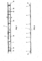
- the in the Fig. 1 and 2 Guard rails 1 and 2 differ only by the guard rail 5 and 6.
- the guard rail 5 is box-shaped, while the guard rail 6 is formed in cross-section W-shaped.
- the embodiment with the guardrail 5 is also shown.
- the crash barriers 5 and 6 are known per se and form only examples here. There are therefore other crash barriers conceivable.
- the crash barriers 5 and 6 are each fastened with fastening means 24 and 25 to the post 3, which are anchored along a roadway in the ground. Below the crash barriers 5 and 6, a retaining device 7 is attached to the post 3 in each case.
- the retaining device 7 consists of an underrun protection plate 8 and brackets 9, with which the underrun protection plate 8 is releasably secured to the post 3.
- the Unterfahrtikstrang 8 has an upper edge 26 which extends horizontally at a distance to the guardrail 5 and 6 respectively.
- a lower edge 27 is spaced from a road surface 4 or according to Fig. 6 arranged to the top 37 of a banquet.
- the brackets 9 hold the underrun guard 8 at a distance from the posts 3 in a position in which a front side 19 as shown is inclined to the road surface 4 and the top 37 so that the upper edge 26 to the posts 3 has a smaller distance than the lower edge 27.
- the inclination is comparatively small and is preferably less than 10 °.
- Each bracket 9 is connected to a fastening screw 29 and a nut 30 with the underride guard 8.
- the nuts 30 are each mounted behind a breakthrough 18 on a back 20 of the bracket 9 and the underride guard plate 8 and pre-assembled, so that the mounting screws 29 can be screwed in each case without holding the nuts 30.
- the fastening screws 19 are preferably formed so that they protrude only slightly at the front side 29 and form no risk of injury in the event of an impact.
- the underrun protection plate 8 is bent at the upper edge 26 and at the lower edge 27 to the rear, so that can not injure the impact of the body at these edges.
- the brackets 9 are each made of a strip-shaped piece of sheet metal with a thickness of preferably about 2.5 mm and have an upper portion 14, a central region 15 and a lower portion 16.
- the central region 15 serves for the attachment of the underrun protection plate 8, which lies flat against this area 15 with a rear side 31.
- the upper region 14 has a turn 17, on which a plug-in device 10 is arranged.
- This plug-in device 10 consists of a rearwardly projecting first pin 11 and a second pin 12, which is arranged on a bent tab 13 and which extends over the first pin 11 substantially parallel to the longitudinal direction of the underrun protection 8.
- the first pin 11 is inserted into a bore 32 of the post 3.
- the second bolt 12 engages behind a side part 33 of the post 3 and is applied to this.
- the plug-in devices 10 of adjacent brackets 9 are arranged so that the one bracket on the side part 33 shown and the other bracket is attached to the other mirror-image side part of the adjacent post. In the view according to Fig. 8 Thus, one bracket 9 is attached from the right and the other adjacent bracket 9 from the left. This is a very stable, immovable without the use of mounting screws Attachment of the retaining device 7 to the post 3 possible.
- the plug-in device 10 allows mounting of the bracket 9 without the use of a tool.
- the plug connection in contrast to a screw connection, is not completely rigid, so that the bolts 11 and 12 can move in at least one direction in the event of a body impacting on the retaining device 7, which results in deformation and thus in the kinetic energy conversion in the region of Plug devices 10 allows.
- the tabs 13 and the bolts 11 and 12 are bent.
- the lower portion 16 is inclined at an angle to the corresponding post 3 and supported by a lower edge 34 on a front side 35 of the post 3.
- the bracket 9 in the event of an impact along the front side 35 slide down.
- the bracket 9 in such a deformation of the corresponding bracket 9 'increasingly flat.
- the gap 28 is thus reduced. The risk that a body part can pass through the gap 28 is thus avoided.
- the deformation, as in Fig. 6 is shown schematically, may of course be different depending on the impact of a body.
- the deformation of the plug-in device, which can also occur, is not shown here.
- the Unterfahrtikstrang 8 is deformed and here according to Fig. 6 to one or more of the posts 3, especially at the lower edge 27, pressed.
- FIG. 7 shows the Unterfahrtikstrang 8 of a plurality of strip-shaped Abkant sheet metal elements 38 and two attached to the ends and bent Endbögen 39. These bending sheet metal elements 38 and end bows 39 are each screwed together at their ends with mounting screws 40. The number and length of the sheet metal elements 38 can of course be very different.
- the invention enables a simple retrofitting of an existing crash barrier arrangement, which has a plurality of posts 3 and a guard rail 5 or 6. In the following, this method will be explained in more detail.
- bracket 9 is provided for the attachment of the underrun protection 8 posts 3 with a bore 32.
- This bore 32 is located according to the Fig. 1 and 2 At this front and thus visible side part 33.
- the first pin 11 of a bracket 9 is now inserted inclined and at the same time the bracket 9 is pivoted so that the second pin 12 engages behind the side part 33 and finally the bracket 9 with the back of the Abbugs 17 flat against the front side 35 of the post 3.
- the bracket 9 is thus attached without the use of a tool on the post 3.
- the adjacent post 3, not shown here is provided at the same height, but on the mirror-image side part 33 with a bore and at this another bracket 9 is attached in the same way.
- a sheet metal element 38 is now created and secured with two screws 29.
Landscapes
- Engineering & Computer Science (AREA)
- Architecture (AREA)
- Civil Engineering (AREA)
- Structural Engineering (AREA)
- Refuge Islands, Traffic Blockers, Or Guard Fence (AREA)
Applications Claiming Priority (1)
| Application Number | Priority Date | Filing Date | Title |
|---|---|---|---|
| CH01572/11A CH705555B1 (de) | 2011-09-22 | 2011-09-22 | Leitplankenanordnung mit einer Rückhalteeinrichtung für Motorradfahrer und Verfahren zum Nachrüsten einer Leitplankenanordnung mit einer Rückhalteeinrichtung für Motorradfahrer. |
Publications (2)
| Publication Number | Publication Date |
|---|---|
| EP2573271A2 true EP2573271A2 (fr) | 2013-03-27 |
| EP2573271A3 EP2573271A3 (fr) | 2016-10-19 |
Family
ID=46146697
Family Applications (1)
| Application Number | Title | Priority Date | Filing Date |
|---|---|---|---|
| EP12168240.5A Withdrawn EP2573271A3 (fr) | 2011-09-22 | 2012-05-16 | Agencement de glissière de sécurité avec dispositif de retenue pour conducteurs de motos et procédé d'équipement d'une glissière de sécurité avec un dispositif de retenue pour conducteurs de motos |
Country Status (2)
| Country | Link |
|---|---|
| EP (1) | EP2573271A3 (fr) |
| CH (1) | CH705555B1 (fr) |
Cited By (1)
| Publication number | Priority date | Publication date | Assignee | Title |
|---|---|---|---|---|
| US20180282957A1 (en) * | 2015-04-02 | 2018-10-04 | Arcelormittal | Spacer for Road Safety Barrier |
Citations (5)
| Publication number | Priority date | Publication date | Assignee | Title |
|---|---|---|---|---|
| DE2513436A1 (de) | 1974-03-28 | 1975-10-02 | Voest Ag | Sicherheitsleitplanke |
| FR2546932A1 (fr) | 1983-06-01 | 1984-12-07 | Routier Equip Sa | Systeme de protection de points durs pour voies de circulation routiere |
| EP1184515A1 (fr) | 2000-08-25 | 2002-03-06 | Sec Envel S.à.r.l. | Barrière de sécurité pour voies de circulation de véhicules munie d'au moins un écran de protection |
| DE102005004918A1 (de) | 2005-02-02 | 2005-12-01 | Spig Schutzplanken-Produktions-Gesellschaft Mbh & Co Kg | Leitplankenanordnung |
| DE102004038982A1 (de) | 2004-08-10 | 2006-03-09 | Spig Schutzplanken-Produktions-Gesellschaft Mbh & Co Kg | Leitschwellenanordnung |
Family Cites Families (2)
| Publication number | Priority date | Publication date | Assignee | Title |
|---|---|---|---|---|
| DE29903787U1 (de) * | 1999-03-03 | 1999-05-27 | Spig Schutzplanken-Produktions-Gesellschaft mbH & Co KG, 66839 Schmelz | Schutzplankenanordnung |
| FR2852034B1 (fr) * | 2003-03-06 | 2005-05-20 | Profilafroid Equipement De La | Dispositif de fixation d'un ecran de protection pour glissieres de securite |
-
2011
- 2011-09-22 CH CH01572/11A patent/CH705555B1/de unknown
-
2012
- 2012-05-16 EP EP12168240.5A patent/EP2573271A3/fr not_active Withdrawn
Patent Citations (5)
| Publication number | Priority date | Publication date | Assignee | Title |
|---|---|---|---|---|
| DE2513436A1 (de) | 1974-03-28 | 1975-10-02 | Voest Ag | Sicherheitsleitplanke |
| FR2546932A1 (fr) | 1983-06-01 | 1984-12-07 | Routier Equip Sa | Systeme de protection de points durs pour voies de circulation routiere |
| EP1184515A1 (fr) | 2000-08-25 | 2002-03-06 | Sec Envel S.à.r.l. | Barrière de sécurité pour voies de circulation de véhicules munie d'au moins un écran de protection |
| DE102004038982A1 (de) | 2004-08-10 | 2006-03-09 | Spig Schutzplanken-Produktions-Gesellschaft Mbh & Co Kg | Leitschwellenanordnung |
| DE102005004918A1 (de) | 2005-02-02 | 2005-12-01 | Spig Schutzplanken-Produktions-Gesellschaft Mbh & Co Kg | Leitplankenanordnung |
Cited By (2)
| Publication number | Priority date | Publication date | Assignee | Title |
|---|---|---|---|---|
| US20180282957A1 (en) * | 2015-04-02 | 2018-10-04 | Arcelormittal | Spacer for Road Safety Barrier |
| US10648142B2 (en) * | 2015-04-02 | 2020-05-12 | Arcelormittal | Spacer for road safety barrier |
Also Published As
| Publication number | Publication date |
|---|---|
| CH705555A2 (de) | 2013-03-28 |
| CH705555B1 (de) | 2018-09-28 |
| EP2573271A3 (fr) | 2016-10-19 |
Similar Documents
| Publication | Publication Date | Title |
|---|---|---|
| EP2794997B1 (fr) | Structure de protection | |
| DE3640821C1 (en) | Protective barrier arrangement | |
| EP1762660B1 (fr) | Dispositif de guidage routier | |
| EP2455546A1 (fr) | Agencement de poteau pour une construction de glissière de sécurité et construction de glissière de sécurité pour sécuriser des bandes de roulement sur des chantiers | |
| EP2148008A2 (fr) | Dispositif de glissière de sécurité | |
| DE202012104881U1 (de) | Barriereelement und Barriere aus zumindest zwei miteinander verbundenen Barriereelementen | |
| EP3827128B1 (fr) | Système de retenue de véhicule avec montant | |
| EP2333159B1 (fr) | Glissière de sécurité | |
| DE102013011189C5 (de) | Kraftwagenbug eines Personenkraftwagens | |
| DE102007063511B4 (de) | Schutzeinrichtung an Verkehrswegen | |
| EP2573271A2 (fr) | Agencement de glissière de sécurité avec dispositif de retenue pour conducteurs de motos et procédé d'équipement d'une glissière de sécurité avec un dispositif de retenue pour conducteurs de motos | |
| DE102011055960B4 (de) | Fahrzeugrückhaltesystem | |
| DE10356220B4 (de) | Sicherungseinrichtung für befahrbare oder begehbare Flächen | |
| DE202004013606U1 (de) | Passive Schutzeinrichtung neben einer Fahrbahn einer Kraftfahrzeugstraße | |
| EP3312344B1 (fr) | Dispositif de glissières de sécurité doté du poteau d'arrimage | |
| EP2904153B1 (fr) | Système de retenue et structure de transition entre deux systèmes de retenue de véhicules présentant des rigidités latérales différentes | |
| EP3190232B1 (fr) | Protection anti-encastrement | |
| DE10306744B4 (de) | Absturzsicherung und Anprallschutz | |
| DE202008011203U1 (de) | Fahrzeugrückhaltesystem an Verkehrswegen | |
| EP2567030B1 (fr) | Glissière de sécurité | |
| AT409005B (de) | Leiteinrichtung | |
| AT513840B1 (de) | Fahrzeugrückhaltesystem | |
| DE202006013759U1 (de) | Schutzeinrichtung an Verkehrswegen | |
| DE202012005532U1 (de) | Übergangsschutzplankenkonstruktion | |
| DE202025106340U1 (de) | Mobile Fahrzeugsicherheitsbarriere |
Legal Events
| Date | Code | Title | Description |
|---|---|---|---|
| PUAI | Public reference made under article 153(3) epc to a published international application that has entered the european phase |
Free format text: ORIGINAL CODE: 0009012 |
|
| AK | Designated contracting states |
Kind code of ref document: A2 Designated state(s): AL AT BE BG CH CY CZ DE DK EE ES FI FR GB GR HR HU IE IS IT LI LT LU LV MC MK MT NL NO PL PT RO RS SE SI SK SM TR |
|
| AX | Request for extension of the european patent |
Extension state: BA ME |
|
| PUAL | Search report despatched |
Free format text: ORIGINAL CODE: 0009013 |
|
| AK | Designated contracting states |
Kind code of ref document: A3 Designated state(s): AL AT BE BG CH CY CZ DE DK EE ES FI FR GB GR HR HU IE IS IT LI LT LU LV MC MK MT NL NO PL PT RO RS SE SI SK SM TR |
|
| AX | Request for extension of the european patent |
Extension state: BA ME |
|
| RIC1 | Information provided on ipc code assigned before grant |
Ipc: E01F 15/04 20060101AFI20160909BHEP |
|
| 17P | Request for examination filed |
Effective date: 20170412 |
|
| RBV | Designated contracting states (corrected) |
Designated state(s): AL AT BE BG CH CY CZ DE DK EE ES FI FR GB GR HR HU IE IS IT LI LT LU LV MC MK MT NL NO PL PT RO RS SE SI SK SM TR |
|
| 17Q | First examination report despatched |
Effective date: 20170628 |
|
| STAA | Information on the status of an ep patent application or granted ep patent |
Free format text: STATUS: THE APPLICATION IS DEEMED TO BE WITHDRAWN |
|
| 18D | Application deemed to be withdrawn |
Effective date: 20180109 |