EP2573300A2 - Motor vehicle door lock - Google Patents
Motor vehicle door lock Download PDFInfo
- Publication number
- EP2573300A2 EP2573300A2 EP20120175880 EP12175880A EP2573300A2 EP 2573300 A2 EP2573300 A2 EP 2573300A2 EP 20120175880 EP20120175880 EP 20120175880 EP 12175880 A EP12175880 A EP 12175880A EP 2573300 A2 EP2573300 A2 EP 2573300A2
- Authority
- EP
- European Patent Office
- Prior art keywords
- pawl
- movement
- rotary latch
- motor vehicle
- vehicle door
- Prior art date
- Legal status (The legal status is an assumption and is not a legal conclusion. Google has not performed a legal analysis and makes no representation as to the accuracy of the status listed.)
- Granted
Links
Images


Classifications
-
- E—FIXED CONSTRUCTIONS
- E05—LOCKS; KEYS; WINDOW OR DOOR FITTINGS; SAFES
- E05B—LOCKS; ACCESSORIES THEREFOR; HANDCUFFS
- E05B77/00—Vehicle locks characterised by special functions or purposes
- E05B77/36—Noise prevention; Anti-rattling means
-
- E—FIXED CONSTRUCTIONS
- E05—LOCKS; KEYS; WINDOW OR DOOR FITTINGS; SAFES
- E05B—LOCKS; ACCESSORIES THEREFOR; HANDCUFFS
- E05B81/00—Power-actuated vehicle locks
- E05B81/12—Power-actuated vehicle locks characterised by the function or purpose of the powered actuators
- E05B81/14—Power-actuated vehicle locks characterised by the function or purpose of the powered actuators operating on bolt detents, e.g. for unlatching the bolt
-
- E—FIXED CONSTRUCTIONS
- E05—LOCKS; KEYS; WINDOW OR DOOR FITTINGS; SAFES
- E05B—LOCKS; ACCESSORIES THEREFOR; HANDCUFFS
- E05B81/00—Power-actuated vehicle locks
- E05B81/12—Power-actuated vehicle locks characterised by the function or purpose of the powered actuators
- E05B81/20—Power-actuated vehicle locks characterised by the function or purpose of the powered actuators for assisting final closing or for initiating opening
-
- E—FIXED CONSTRUCTIONS
- E05—LOCKS; KEYS; WINDOW OR DOOR FITTINGS; SAFES
- E05B—LOCKS; ACCESSORIES THEREFOR; HANDCUFFS
- E05B83/00—Vehicle locks specially adapted for particular types of wing or vehicle
- E05B83/16—Locks for luggage compartments, car boot lids or car bonnets
- E05B83/18—Locks for luggage compartments, car boot lids or car bonnets for car boot lids or rear luggage compartments
-
- E—FIXED CONSTRUCTIONS
- E05—LOCKS; KEYS; WINDOW OR DOOR FITTINGS; SAFES
- E05B—LOCKS; ACCESSORIES THEREFOR; HANDCUFFS
- E05B81/00—Power-actuated vehicle locks
-
- Y—GENERAL TAGGING OF NEW TECHNOLOGICAL DEVELOPMENTS; GENERAL TAGGING OF CROSS-SECTIONAL TECHNOLOGIES SPANNING OVER SEVERAL SECTIONS OF THE IPC; TECHNICAL SUBJECTS COVERED BY FORMER USPC CROSS-REFERENCE ART COLLECTIONS [XRACs] AND DIGESTS
- Y10—TECHNICAL SUBJECTS COVERED BY FORMER USPC
- Y10T—TECHNICAL SUBJECTS COVERED BY FORMER US CLASSIFICATION
- Y10T292/00—Closure fasteners
- Y10T292/08—Bolts
- Y10T292/0911—Hooked end
- Y10T292/0945—Operating means
Definitions
- the invention is directed to a motor vehicle door lock with a closed position in the closed position closing element and in the direction of the closing element biased open position rotary latch, a pawl which engages in an engaged position with the rotary latch in such a manner that the rotary latch on a movement in the direction of the open position is prevented, and a drive member to which a coupling portion of the pawl is coupled for movement and which moves the pawl between the engaged position and a release position in which the pawl is disengaged from the rotary latch, so that the rotary latch can move in the direction of the open position.
- the present invention relates to a method for opening a motor vehicle door lock, which surrounds a closed position in the closed position and a closing element releasing the closing element biased rotary latch, a pawl which engages in a latched position with the rotary latch in such a manner that the rotary latch on a Movement is prevented in the direction of the open position, and a drive element to which a coupling portion of the pawl is coupled for movement and which moves the pawl between the engaged position and a release position in which the pawl is disengaged from the rotary latch, so that the rotary latch in the direction the open position can move, wherein the pawl and the rotary latch are disengaged for opening by the pawl is at least partially pivoted away from the rotary latch.
- a motor vehicle door lock of the type mentioned above is used, for example, in a tailgate of a motor vehicle and comprises a connected to a trunk lid, usually designed as a rotary latch lock element and connected to a body of the vehicle lock counterpart, which may be formed in the form of a striker or latch bolt.
- a user actuates (eg by means of an electronic key) a control device, by means of which the tailgate can be opened by means of a drive element, which is preferably operated by an electric motor.
- a pivotally mounted pawl from an engagement position in which the pawl is in engagement with the rotary latch, deflected in the direction of a release position of the drive element until it has reached the release position and is no longer engaged with the catch, whereby a rotational movement the catch is released from the closed position in the direction of an open position.
- the invention has for its object to provide a solution that provides a motor vehicle door lock in a structurally simple manner and cost, in which the opening noise is reduced to a minimum, or at least in which the opening process no clearly audible and the comfort negatively impairing noise generated.
- the object is achieved in that the drive element moves the pawl during movement from the engaged position in the direction of the release position such that in this Movement with the pawl still engaged catch in the direction of the open position moves.
- the object of a method of the type mentioned in the present invention is achieved in that the pawl is moved by the drive element during movement from the engaged position in the direction of the release position such that in this movement with the pawl still engaged rotary latch is moved in the direction of the open position.
- the movement of the rotary latch can be a rotation both in the motor vehicle door lock according to the invention and in the method according to the invention.
- the invention provides a motor vehicle door closure and a method of opening the motor vehicle door closure, which contribute to increasing the comfort and quality of the closure and its operation.
- the motor vehicle door lock according to the invention is characterized by a functional design and has a simple and inexpensive construction.
- the bias of the tailgate degrades, since the defined movement of the pawl causes a relative movement between the motor vehicle door lock and the closing element and thus relieving the tailgate, wherein the rotary latch to a predetermined rotational movement in the open position is turned.
- the invention provides that the movement of the drive element is a rotary movement, during the movement of the pawl from the engaged position in the direction of the release position with respect to the catch substantially tangential movement of the pawl and then disengage the pawl and the catch, causing movement of the pawl substantially radially away from the catch.
- This movement refers to a latching portion of the pawl, which engages in the engaged position with the rotary latch.
- the drive element for opening the motor vehicle door lock is rotated such that the pawl or at least a portion of the pawl, ie the latching portion, initially during movement from the engaged position in the direction of the release position is moved substantially tangentially with respect to the rotary latch and then to disengage the pawl and the catch, is moved substantially radially away from the catch.
- the movement of the pawl executed during the opening process of the motor vehicle door lock is thus divided into two or consists of a sequence of movements in which the pawl is moved in at least two different spatial directions. To initially take the pressure from the tailgate in the closed position or to relieve the preloaded tailgate, there is a substantially tangential movement of the pawl with respect to the rotary latch.
- the rotary latch is rotatably supported by means of a fixedly arranged on a housing element of the motor vehicle door lock pivot axis or if the rotary latch is rotatably mounted on a housing element of the motor vehicle door lock about a rotation axis. Furthermore, it is advantageous in this case if the coupling portion of the pawl, which is coupled to the drive element in a manner of movement, is attached to a connecting element and about this pivotally.
- the connecting element defines a joint for the pawl, wherein the joint during the movement of the pawl in the direction of the release position relative to the rotational axis of the rotary latch moves translationally.
- the pawl is indeed still engaged with the rotary latch, however, can rotate due to the translational and tangential to the rotary latch movement of the pawl, the rotary latch in the direction of its open position.
- the invention provides that the drive element is rotatably mounted on a housing element of the motor vehicle door lock about a rotation axis.
- the connecting element or the joint is arranged on the drive element radially offset from the axis of rotation.
- the pawl rotates with rotation of the drive element together with the drive element, wherein the pawl is not rigidly mounted, but pivotally mounted on the drive element, so that the drive movement of the drive element pivoting and / or possibly translational Movement of the pawl causes.
- a rotation of the drive element can thus effect in a structurally simple manner a substantially translational movement of the pawl in the manner of a simple toggle lever.
- the invention provides in an embodiment that a push rod is provided, of which a first end is pivotally and radially offset from the axis of rotation with the drive element and of which a second end receives the movement coupled to the coupling portion of the pawl connecting element, wherein a first end of a hinge lever to a mounted on the housing element guide axis is fixed and rotatably mounted and a second end of the articulated lever, the push rod and the movement-coupled with the pawl connection element rotatably and pivotally supports.
- a first toggle lever is defined by the second end of the push rod and the fixedly mounted toggle lever, wherein the pawl is coupled via the connecting element with the toggle lever and with the push rod.
- a second toggle lever is defined by the first end of the push rod and its eccentric or radially offset with respect to the axis of rotation coupling with the drive element.
- the pawl has a bend, which rests in the engaged position on the acting as an end stop and the movement of the pawl on the engagement position addition limiting guide axis.
- the push rod or its line of force assumes a position in which it has exceeded a dead center and thereby locked in the engaged position self-locking, the guide shaft as mechanical stop acts.
- the preload, with which the tailgate is biased in the closed position, gradually and not abruptly degraded it is in an embodiment of the invention further advantageous if the movement from the engaged position in the direction of the release position of the connecting element pivotally mounted coupling portion of the pawl is a circular segment-shaped movement. It is conceivable, for example, quarter-circle or semi-circular movements.
- a structurally particularly simple way of defined guidance of the pawl in the release position is in a further embodiment of the motor vehicle door lock in that a in the engaged position with the rotary catch engaging latching portion of the pawl by means of a guide member and / or attached to the pawl control pin is.
- the pawl is moved radially away from the rotary latch during the opening process, it being particularly advantageous if only the portion of the pawl engaged with the catch and not the entire pawl is moved away from the rotary latch.
- the guide element is pivotally mounted on a housing element of the motor vehicle door lock and has a guide recess, which movement of the catch engageable with the catch portion of the pawl leading to the catch or away from the catch.
- the guide element could also be formed on the catch itself and ensure that the latching portion of the pawl is disengaged from the catch.
- the pawl is biased in the direction of the engagement position.
- the pawl is permanently urged in the direction of the engagement position, which can be achieved for example by means of at least one spring element, which may be formed as a tension or compression spring. It is sufficient if only the portion of the pawl is biased, which can be brought into engagement with the rotary latch or is in engagement with the rotary latch.
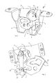
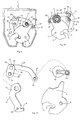
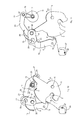
- FIGS. 1 to 13 show schematically in different views only the essential elements of the invention of a motor vehicle door closure 1, in particular a tailgate lock assembly, wherein the FIGS. 1 to 8 a first embodiment and the FIGS. 9 to 13 represent a second embodiment of the motor vehicle door closure 1 according to the invention.
- FIGS. 2 to 8 show the FIGS. 2 to 8 the assembled motor vehicle door lock 1.
- the FIGS. 4 to 7 show different positions of the components of the motor vehicle door lock 1 during the opening process, whereas FIG. 8 shows a position during the closing process.
- the closing element 2 may be formed, for example, as a locking pin or striker and is attached to a vehicle frame.
- the in FIG. 1 shown in an exploded view of the motor vehicle door closure 1 according to the first embodiment comprises interconnectable housing elements 3 and 4, a rotary latch 5 which is rotatably mounted about an axis of rotation 6 on the housing element 2 and a rotary latch jaw 7, in which the closing element 2 engages.
- the rotary latch 5 is characterized by a in FIG. 3 only schematically indicated spring element 23 biased such that it strives to be in the in the FIGS.
- FIG. 4 to 7 shown counterclockwise (arrow A) to rotate, so that the closing element 2 (in the FIGS. 4 to 7 downwards) is released.
- the catch 5 is held by a pawl 8 by a locking portion 9 of the pawl 8 with a latching arm 10 on the rotary latch jaw 7 is engaged.
- the FIG. 4 shown position is the so-called locking position, in which the catch 5 are in a closed position and the pawl 8 in an engaged position.
- the rotary latch 5 presses with its locking arm 10 in the locking position on the latching portion 9 of the pawl 8, whereby the closing element 2 is fixed in the rotary latch jaw 7, as from FIG. 4 is apparent.
- the rotary latch 5 is biased in the direction of the closing element 2 releasing open position.
- the pawl 8 is engaged with the rotary latch 5 in such a way that the rotary latch 5 is prevented from moving in the direction of the open position.
- the pawl 8 is connected in a motion-coupled manner to a drive element 11.
- the drive element 11 is rotatably mounted on the housing element 4 about a rotation axis 12.
- the connecting element 13 connects the drive element 11 with a coupling portion 14 of the pawl 8, so that the drive element 11, the pawl 8 between the engaged position and a release position in which the pawl 8 is brought out of engagement with the rotary latch 5 moves.
- the pawl 8 is thus mounted by means of the connecting element 13 pivotally mounted on the drive element 11 radially offset from the axis of rotation 12 thereof.
- the rotary latch 5 can move or rotate in the direction of the open position.
- the pawl 8 is biased in the direction of the engagement position, which, for example, by means of an example only in FIG FIG. 3 it is sufficient if the region of the latching portion 9 of the pawl 8 is urged by the spring force in the engaged position and thus in the direction of the rotary latch 5 and the latching arm 10 of the rotary latch 5.
- the invention provides that the drive element 11 moves the pawl 8 during movement from the engaged position in the direction of the release position such that in this movement with the pawl 8 still engaged or located rotary latch 5 moves in the direction of the open position.
- the bias of the tailgate is reduced or reduced, since the tailgate can move due to the described motion coupling to a defined stroke from the locked position.
- FIGS. 4 to 7 Show intermediate positions of the rotary latch 5 and the pawl 8.
- FIGS. 4 to 7 is a movement curve 15 of the connecting element 13 and the coupling portion 14 which is connected via the connecting element 13 to the drive element 11, shown in dashed lines.
- the movement curve 15 essentially corresponds to the control recesses 22a and 22b, which are formed in the housing elements 3 and 4. It can be seen from the movement curve 15 that the movement of the coupling portion 14 of the pawl 8 pivotally mounted on the connecting element 13 from the engagement position in the direction of the release position is a circular-segment-shaped movement which is illustrated in FIGS FIGS. 4 to 7 counterclockwise in the direction of arrow A. Accordingly, a rotational movement of the drive member 11 causes the coupling portion 14 of the pawl 8 to be moved along a circle portion.
- control recesses 22a and 22b formed in the housing elements 3 and 4 can additionally guide the movement of the connecting element 13.
- the control recesses 22a and 22b are dispensable, so that they can be omitted in the motor vehicle door lock according to the invention.
- the pawl 8 is moved by the drive member 11 during movement from the engaged position in the direction of the release position such that in this movement with the pawl 8 still engaged rotary latch 5 is moved in the direction of the open position ,
- the drive element 11 is rotated to open the motor vehicle door latch 1 such that the pawl 8 or at least a portion of the pawl 8 is first moved during movement from the engaged position in the direction of the release position substantially tangentially with respect to the rotary latch 5 and then to the Pawl 8 and the catch 5 to disengage, is moved by the rotary latch 5 substantially radially away.
- the movement of the coupling portion 14, which due to the movement coupling with the Drive element 11 of the circular segment-shaped movement curve 15 follows, from the movement of the latching portion 9 of the pawl 8 from.
- the locking portion 9, which is in the engaged position of the pawl 8 with the rotary latch 5 is engaged, is guided by means of a guide member 16.
- the guide element 16 is arranged on the housing element 3 of the motor vehicle door lock and mounted pivotably about an axis 17. Further, the guide member 16 has a guide recess 18 with two opposing abutment surfaces, which leads or controls a movement of the engageable with the catch 5 locking portion 9 of the pawl 8 toward the rotary latch 5 or away from the rotary latch 5.
- the movement of a control pin 19 can be performed, which is formed in the region of the latching portion 9 of the pawl 8 (Siege FIGS. 4 and 8 ).
- the movement of the guide element 16 itself can be achieved by a movement limiting recess 20 formed in the housing element 3 (see FIG FIG. 1 ) be limited.
- the latching portion 9 of the pawl may, as mentioned above, be biased in the direction of the engagement position by means of the spring element 24, so that the formed in the region of the latching portion 9 control pin 19 during the in the FIGS. 4 to 7 shown movement process is urged radially in the direction of the rotary latch 5 at the outermost end of the formed in the guide member 16 guide recess 18.
- a radial movement away from the catch 5 could be effected by itself.
- an outer portion of the rotary latch 5 could have a radial projection 21, as in FIG FIG. 4 indicated by dashed lines or shown.
- the radial projection 21 would arrive at sufficient rotation in abutment against the pawl 8 and the pawl 8 push away or deflect such that the locking portion 9 and the locking arm 10 are disengaged.
- FIG. 8 a position of the motor vehicle door lock 1 is shown during the closing operation, in which the coupling portion 14 of the pawl 8 is again in the engaged position, whereas the locking portion 9 of the pawl 8 is arranged radially away from the rotary latch 5, wherein the control pin 19 has a central position in the guide recess 18 of the guide member 16 occupies. Due to the fact that the control pin 19 of the latching section 9 can be urged radially away from the rotary latch 5 against the force of the spring element 24 in the guide recess 18 of the guide element 16, it is possible for the rotary latch 5 to rotate in the direction of the arrow B during the closing operation and in this movement, the latching arm 10 slides past the latching section 9.
- the bias of the pawl 8 ensures that when the latching arm 10 has passed the latching portion 9, both interlock or that the latching portion 9 then pushes over the latching arm 10 and ensures engagement of pawl 8 and 5 catch, so that in FIG. 4 shown closed position is taken again.
- the process of closing but should not be considered here in detail, because the invention is primarily directed to the processes when opening the motor vehicle door lock.
- FIGS. 9 to 13 the motor vehicle door lock 1 according to the second embodiment is shown.
- the motor vehicle door lock 1 according to the second embodiment - as well as the first embodiment - a housing element 3, which for reasons of clarity, only in FIG. 9 is shown, a rotatably mounted around and on a rotation axis 6 rotary latch 5 with a rotary latch jaw 7, in which in the engaged position, the closing element 2 is arranged, and with a latching arm 10, which engages with a latching portion 9 of the pawl 8 in the engaged position, and a drive element 11 which is rotatable about a rotation axis 12.
- the spring elements 23 and 24 was in the FIGS.
- the pawl 8 is connected to the drive element 11 in a motion-coupled manner.
- this coupling between the first and second embodiments, which will be discussed later in the description of the second embodiment.
- the coupling section 14 of the pawl 8 is pivotally mounted or mounted on the connecting element 13.
- the connecting element 13 defines a joint or a pivot axis 25.
- the hinge or the pivot axis 25 is not fixed in contrast to the axis of rotation 6, but moves during the movement of the pawl 8 in the direction of the release position relative to the axis of rotation 6 of the rotary latch 5 in translation along in the FIGS. 12 and 13 Through this movement curve 15 of the coupling portion 14 of the pawl 8 undergoes a circular segment-shaped movement, which is not a rotational but a translational movement.
- a first end 27 of the push rod 26 is coupled to the drive element 11.
- the first end 27 of the push rod 26 is mounted radially offset from the axis of rotation 12 on a radial projection 28 of the drive member 11 on this rotatably or pivotally.
- the push rod 26 is slightly bent, wherein a second end 29 of the push rod 26 receives the movement coupled to the coupling portion 14 of the pawl 8 connecting element 13.
- a first end 30 of a hinge lever 31 is rotatably mounted on a mounted on the housing element 3 guide axis or hinge axis 32.
- a second end 33 of the articulated lever 31 supports the push rod 26 and the connecting element 13 movably coupled to the pawl 8 so as to be rotatable and pivotable.
- FIG. 12 the motor vehicle door lock 1 according to the second embodiment is shown in the locking or engagement position, whereas in FIG. 13 the open position of the motor vehicle door lock 1 is shown.
- the coupling section 14 also follows a movement from the open position into the engaged position of the movement path 36.
- the transmitted force is converted by the articulated lever 31 in a defined movement of the coupling portion 14, as described above has been.
- the power transmission of the articulated lever 31 define a first toggle lever and the radial shoulder 28 26 a second toggle lever, which cause a particularly powerful motion coupling.
- the second toggle secures the first toggle, especially since the moments on the second toggle are very small, so it can be well secured by low forces. For reasons of safety, it is further desirable that the motor vehicle door latch 1 remains in the closed position even in the event of a vehicle accident.
- the vehicle door latch 1 must withstand the acceleration forces prevailing in a vehicle accident so that the pawl and the rotary latch are not disengaged.
- the pawl 8 a bend 35 (see Figures 10 and 13 ) in the engaged position ( Figures 10 and 12 ) acts on the end stop as acting and the movement of the pawl 8 beyond the engagement position limiting guide shaft 32.
- the push rod 26 assumes a position in which it has exceeded a dead center and thereby locked in the engaged position self-locking.
- the guide shaft 32 serves as a mechanical stop, which limits the movement of the pawl 8 from the open position into the engaged position.
- a motor vehicle door lock 1 was presented, which is characterized in that the noise during opening is reduced to a minimum and in particular the noise is minimized in the discharge stroke. This is achieved in that during the opening operation, the pawl 8 and the rotary latch 5 are moved to each other so that the tailgate and thus the vehicle door latch 1 can remove relative to the closing element 2, whereby the load on the tailgate pressure or the bias of the tailgate is first reduced before the pawl 8 and the catch 5 finally disengaged to release the closure element 2.
Landscapes
- Lock And Its Accessories (AREA)
- Power-Operated Mechanisms For Wings (AREA)
Applications Claiming Priority (2)
| Application Number | Priority Date | Filing Date | Title |
|---|---|---|---|
| DE102011053901 | 2011-09-23 | ||
| DE201210102723 DE102012102723A1 (de) | 2011-09-23 | 2012-03-29 | Kraftfahrzeugtürverschluss |
Publications (3)
| Publication Number | Publication Date |
|---|---|
| EP2573300A2 true EP2573300A2 (fr) | 2013-03-27 |
| EP2573300A3 EP2573300A3 (fr) | 2014-02-12 |
| EP2573300B1 EP2573300B1 (fr) | 2015-10-14 |
Family
ID=46507922
Family Applications (1)
| Application Number | Title | Priority Date | Filing Date |
|---|---|---|---|
| EP12175880.9A Active EP2573300B1 (fr) | 2011-09-23 | 2012-07-11 | Serrure de véhicule automobile |
Country Status (4)
| Country | Link |
|---|---|
| US (1) | US9273497B2 (fr) |
| EP (1) | EP2573300B1 (fr) |
| CN (1) | CN103015816B (fr) |
| DE (1) | DE102012102723A1 (fr) |
Cited By (5)
| Publication number | Priority date | Publication date | Assignee | Title |
|---|---|---|---|---|
| US20140054903A1 (en) * | 2012-08-24 | 2014-02-27 | Kia Motors Corporation | 2-step guide hood latch apparatus for vehicle |
| WO2015090745A1 (fr) * | 2013-12-17 | 2015-06-25 | Huf Hülsbeck & Fürst Gmbh & Co. Kg | Serrure de porte de véhicule automobile |
| WO2016041847A1 (fr) * | 2014-09-16 | 2016-03-24 | Bayerische Motoren Werke Aktiengesellschaft | Serrure pour un élément de carrosserie de véhicule |
| DE102018133301A1 (de) | 2018-12-21 | 2020-06-25 | Kiekert Aktiengesellschaft | Schloss für ein Kraftfahrzeug |
| WO2021078328A1 (fr) * | 2019-10-23 | 2021-04-29 | Kiekert Ag | Serrure de véhicule automobile, en particulier serrure de coffre de véhicule automobile |
Families Citing this family (7)
| Publication number | Priority date | Publication date | Assignee | Title |
|---|---|---|---|---|
| GB2518142B (en) * | 2013-08-22 | 2017-06-28 | Inteva Products Llc | Energy dampening arrangement for vehicle latch assembly |
| GB201408075D0 (en) * | 2014-05-07 | 2014-06-18 | Chevalier John P | Closure and latching mechanisms |
| EP3045387A1 (fr) * | 2015-01-14 | 2016-07-20 | AIRBUS HELICOPTERS DEUTSCHLAND GmbH | Système d'actionnement d'une porte pouvant être actionnée et porte actionnable dotée d'un tel système d'actionnement |
| US10941592B2 (en) * | 2015-05-21 | 2021-03-09 | Magna Closures Inc. | Latch with double actuation and method of construction thereof |
| DE102016107507A1 (de) * | 2016-04-22 | 2017-10-26 | Kiekert Ag | Zuziehhilfe für Kraftfahrzeuge |
| DE102016010467B4 (de) * | 2016-08-31 | 2022-09-22 | Magna BÖCO GmbH | Verriegelungsvorrichtung für eine Fahrzeugtür und Verfahren |
| CN114072563B (zh) * | 2019-07-08 | 2023-01-20 | 麦格纳覆盖件有限公司 | 具有防叩击功能的带动力系紧机构的闭合闩锁组件 |
Family Cites Families (49)
| Publication number | Priority date | Publication date | Assignee | Title |
|---|---|---|---|---|
| US2881021A (en) * | 1955-06-22 | 1959-04-07 | Jervis Corp | Latch mechanism |
| US3386761A (en) * | 1965-11-22 | 1968-06-04 | Gen Motors Corp | Vehicle body door latch and locking system |
| US3378291A (en) * | 1966-04-25 | 1968-04-16 | Gen Motors Corp | Closure latch |
| US3504511A (en) * | 1968-03-04 | 1970-04-07 | Perry E Allen | Electric lock release |
| US3566703A (en) * | 1968-03-28 | 1971-03-02 | Kent Eng | Latch release operating mechanism |
| US3695662A (en) * | 1970-09-18 | 1972-10-03 | Atwood Vacuum Machine Co | Latch for vehicle doors |
| IT1131405B (it) * | 1979-03-24 | 1986-06-25 | Kiekert Soehne Arn | Dispositivo di chiusura a comando centralizzato per porte di veicoli a motore |
| US4440006A (en) * | 1979-03-24 | 1984-04-03 | Kiekert Gmbh & Co. Kommanditgesellschaft | Antitheft central lock system for a motor vehicle |
| DE2911630C2 (de) * | 1979-03-24 | 1982-10-14 | Kiekert GmbH & Co KG, 5628 Heiligenhaus | Elektrische Zentralverriegelungsvorrichtung für Kraftfahrzeugtüren |
| JPS58759Y2 (ja) * | 1979-04-06 | 1983-01-07 | 日産自動車株式会社 | トランクリツドオ−プナ |
| FR2480342A1 (fr) * | 1980-04-14 | 1981-10-16 | Renault | Mecanisme de serrure electrique pour la portee de coffre d'un vehicule automobile |
| FR2518621B1 (fr) * | 1981-12-21 | 1986-03-14 | Kiekert Gmbh Co Kg | Serrure pour porte de vehicule automobile |
| DE3507405C1 (de) * | 1985-03-02 | 1986-05-15 | Daimler-Benz Ag, 7000 Stuttgart | Schliesseinrichtung fuer eine Kraftfahrzeugtuer |
| DE3725075C1 (de) * | 1987-07-29 | 1988-08-18 | Kiekert Gmbh Co Kg | Kraftfahrzeugtuerverschluss |
| US4979384A (en) * | 1987-09-23 | 1990-12-25 | Lectron Products, Inc. | Trunk lid lock with remote release |
| DE3801581C1 (fr) * | 1988-01-21 | 1988-10-13 | Bomoro Bocklenberg & Motte Gmbh & Co Kg, 5600 Wuppertal, De | |
| DE3821840C1 (fr) * | 1988-06-29 | 1989-10-19 | Heraeus Sepatech Gmbh, 3360 Osterode, De | |
| JPH0516364Y2 (fr) * | 1988-09-30 | 1993-04-28 | ||
| IT1233062B (it) * | 1989-02-03 | 1992-03-14 | Motrol Spa | Serratura con incremento del carico di chiusura ed apertura elettrica particolarmente per applicazioni automobilistiche |
| IT217029Z2 (it) * | 1989-04-18 | 1991-10-29 | Motrol Spa | Serratura con incremento del caricodi chiusura ed apertura elettrica particolarmente per un cofano o portellone posteriore di un autoveico lo |
| US4974885A (en) * | 1989-10-31 | 1990-12-04 | Fuji Jukogyo Kabushiki Kaisha | Device for locking trunk lid of motor vehicle |
| JP2533004B2 (ja) * | 1991-02-16 | 1996-09-11 | 三井金属鉱業株式会社 | トランク扉等の電動式ロック装置 |
| DE4311786C2 (de) * | 1993-04-09 | 1995-04-27 | Kiekert Gmbh Co Kg | Kraftfahrzeugtürverschluß, der eine Schließ- und Öffnungshilfe mit motorischem Antrieb aufweist |
| JP2855557B2 (ja) * | 1993-07-30 | 1999-02-10 | 株式会社大井製作所 | 自動車用ドアロック装置 |
| US5613716A (en) * | 1996-01-25 | 1997-03-25 | General Motors Corporation | Electronic vehicle door unlatch control |
| DE19614123A1 (de) * | 1996-04-11 | 1997-10-16 | Bosch Gmbh Robert | Kraftfahrzeug-Klappenschloß oder -Türschloß |
| JPH10196179A (ja) * | 1996-12-27 | 1998-07-28 | Ansei:Kk | ドアロック装置 |
| JPH1171950A (ja) * | 1997-08-29 | 1999-03-16 | Honda Motor Co Ltd | 自動車用ドアロック装置 |
| US6386599B1 (en) * | 1999-08-12 | 2002-05-14 | John Phillip Chevalier | Latch arrangement for automotive door |
| FR2775717B1 (fr) * | 1998-03-03 | 2000-05-05 | Valeo Systemes De Fermetures | Dispositif d'ouverture/fermeture d'un ouvrant, notamment pour vehicule automobile |
| FR2778941B1 (fr) * | 1998-05-20 | 2000-07-28 | Valeo Securite Habitacle | Serrure de porte de vehicule automobile a condamnation electrique |
| DE19828202A1 (de) * | 1998-06-25 | 1999-12-30 | Mannesmann Vdo Ag | Schließeinrichtung für ein bewegliches Element, insbesondere für eine Tür eines Fahrzeuges |
| FR2782110B1 (fr) * | 1998-08-05 | 2000-10-06 | Valeo Securite Habitacle | Serrure de porte a assistance electrique |
| DE10065569B4 (de) * | 1999-12-28 | 2007-12-20 | Ohi Seisakusho Co., Ltd., Yokohama | Vorrichtung zum Öffnen und Schließen von Kraftfahrzeugschlössern |
| US6378920B1 (en) * | 1999-12-30 | 2002-04-30 | Delphi Technologies, Inc. | Deck lid latch |
| WO2002046557A2 (fr) * | 2000-12-07 | 2002-06-13 | Witte-Strattec Llc | Serrure a loquet maintenu en position de fermeture par un cran d'arret |
| DE10214691B4 (de) * | 2002-04-03 | 2013-09-26 | Volkswagen Ag | Verriegelungsvorrichtung |
| DE10327997A1 (de) * | 2003-06-21 | 2005-01-13 | Huf Hülsbeck & Fürst Gmbh & Co. Kg | Schloss für Türen oder Klappen an Fahrzeugen |
| GB2412405B (en) * | 2004-03-24 | 2006-11-01 | Arvinmeritor Light Vehicle Sys | Latch |
| US7258373B2 (en) * | 2004-06-30 | 2007-08-21 | Honda Motor Co., Ltd. | Vehicle lock assembly |
| JP2006233456A (ja) * | 2005-02-22 | 2006-09-07 | Aisin Seiki Co Ltd | ドアロック装置 |
| DE102005048564A1 (de) * | 2005-10-11 | 2007-04-12 | Huf Hülsbeck & Fürst Gmbh & Co. Kg | Schließvorrichtung, insbesondere für Fahrzeuge |
| US7770946B2 (en) * | 2006-07-11 | 2010-08-10 | Kabushiki Kaisha Honda Lock | Door lock device for vehicle |
| DE102007012208A1 (de) * | 2007-03-14 | 2008-09-25 | Kirchhoff Gmbh & Co. Kg | Vorrichtung zur Arretierung eines schwenkbaren Bauteiles eines Kraftfahrzeuges |
| FR2927109B1 (fr) * | 2008-02-01 | 2013-05-31 | Peugeot Citroen Automobiles Sa | Serrure a commande automatique et son dispositif d'actionnement permettant un fonctionnement de la serrure en mode degrade. |
| DE102009021297A1 (de) * | 2009-05-14 | 2010-11-25 | Inteva Products Europe Gmbh | Kraftfahrzeugschloss |
| EP2573301B1 (fr) * | 2011-09-23 | 2017-05-03 | Huf Hülsbeck & Fürst GmbH & Co. KG | Fermeture arrière pour un véhicule automobile |
| DE102012102724A1 (de) * | 2012-03-29 | 2013-10-02 | Huf Hülsbeck & Fürst Gmbh & Co. Kg | Kraftfahrzeugtürverschluss |
| DE102013114180A1 (de) * | 2013-12-17 | 2015-06-18 | Huf Hülsbeck & Fürst Gmbh & Co. Kg | Kraftfahrzeugtürverschluss |
-
2012
- 2012-03-29 DE DE201210102723 patent/DE102012102723A1/de not_active Ceased
- 2012-07-11 EP EP12175880.9A patent/EP2573300B1/fr active Active
- 2012-08-31 US US13/600,694 patent/US9273497B2/en active Active
- 2012-08-31 CN CN201210320529.2A patent/CN103015816B/zh active Active
Non-Patent Citations (1)
| Title |
|---|
| None |
Cited By (7)
| Publication number | Priority date | Publication date | Assignee | Title |
|---|---|---|---|---|
| US20140054903A1 (en) * | 2012-08-24 | 2014-02-27 | Kia Motors Corporation | 2-step guide hood latch apparatus for vehicle |
| US9255429B2 (en) * | 2012-08-24 | 2016-02-09 | Hyundai Motor Company | 2-step guide hood latch apparatus for vehicle |
| WO2015090745A1 (fr) * | 2013-12-17 | 2015-06-25 | Huf Hülsbeck & Fürst Gmbh & Co. Kg | Serrure de porte de véhicule automobile |
| WO2016041847A1 (fr) * | 2014-09-16 | 2016-03-24 | Bayerische Motoren Werke Aktiengesellschaft | Serrure pour un élément de carrosserie de véhicule |
| DE102018133301A1 (de) | 2018-12-21 | 2020-06-25 | Kiekert Aktiengesellschaft | Schloss für ein Kraftfahrzeug |
| WO2020125858A1 (fr) | 2018-12-21 | 2020-06-25 | Kiekert Ag | Serrure conçue pour un véhicule automobile |
| WO2021078328A1 (fr) * | 2019-10-23 | 2021-04-29 | Kiekert Ag | Serrure de véhicule automobile, en particulier serrure de coffre de véhicule automobile |
Also Published As
| Publication number | Publication date |
|---|---|
| DE102012102723A1 (de) | 2013-03-28 |
| EP2573300B1 (fr) | 2015-10-14 |
| US20130076045A1 (en) | 2013-03-28 |
| CN103015816A (zh) | 2013-04-03 |
| CN103015816B (zh) | 2017-04-26 |
| EP2573300A3 (fr) | 2014-02-12 |
| US9273497B2 (en) | 2016-03-01 |
Similar Documents
| Publication | Publication Date | Title |
|---|---|---|
| EP2573300B1 (fr) | Serrure de véhicule automobile | |
| EP2865828B1 (fr) | Fermeture de porte de véhicule automobile | |
| EP2573301B1 (fr) | Fermeture arrière pour un véhicule automobile | |
| EP2859165B1 (fr) | Dispositif d'accouplement destiné à la liaison détachable d'une partie de carrosserie montée de manière à pivoter, telle que les portes d'un véhicule, le hayon ou le capot de ce dernier, à une partie structurelle d'une carrosserie du véhicule | |
| AT500017B1 (de) | Schwenkschiebetür für fahrzeuge | |
| WO2018137817A1 (fr) | Système de poignée de porte pour une porte de véhicule | |
| WO2018137840A1 (fr) | Ensemble poignée de porte pour une portière de véhicule | |
| EP3164283A1 (fr) | Ensemble d'entraînement et commande à clapets | |
| EP3397829B1 (fr) | Ensemble poignée de porte d'un véhicule automobile | |
| DE102009018188B4 (de) | Vorrichtung zum automatischen Schließen einer Fahrzeugtür | |
| EP3734003B1 (fr) | Agencement de poignée de porte | |
| EP2268526A1 (fr) | Verrouillage pour porte pivotante extérieure | |
| EP2803795A2 (fr) | Serrure de véhicule automobile | |
| DE102012107143A1 (de) | Kraftfahrzeugtürverschluss | |
| EP3803006A1 (fr) | Ensemble poignée de porte conçu pour un véhicule automobile | |
| EP2987931A1 (fr) | Serrure de véhicule automobile | |
| DE102013014725A1 (de) | Kraftfahrzeugtürverschluss | |
| EP3084105B1 (fr) | Serrure pour porte de véhicule | |
| DE102012107145A1 (de) | Kraftfahrzeugtürverschluss | |
| EP3847328B1 (fr) | Unité d'entraînement pour des applications en automobile | |
| DE102012107144B4 (de) | Kraftfahrzeugtürverschluss | |
| DE102007052890B4 (de) | Kraftfahrzeugtürverschluss | |
| EP3385482B1 (fr) | Dispositif de verrouillage pour un véhicule | |
| WO2020212070A1 (fr) | Dispositif d'ouverture d'élément en forme d'ailette, ainsi que véhicule | |
| WO2014019851A2 (fr) | Serrure de portière de véhicule automobile |
Legal Events
| Date | Code | Title | Description |
|---|---|---|---|
| PUAI | Public reference made under article 153(3) epc to a published international application that has entered the european phase |
Free format text: ORIGINAL CODE: 0009012 |
|
| AK | Designated contracting states |
Kind code of ref document: A2 Designated state(s): AL AT BE BG CH CY CZ DE DK EE ES FI FR GB GR HR HU IE IS IT LI LT LU LV MC MK MT NL NO PL PT RO RS SE SI SK SM TR |
|
| AX | Request for extension of the european patent |
Extension state: BA ME |
|
| PUAL | Search report despatched |
Free format text: ORIGINAL CODE: 0009013 |
|
| AK | Designated contracting states |
Kind code of ref document: A3 Designated state(s): AL AT BE BG CH CY CZ DE DK EE ES FI FR GB GR HR HU IE IS IT LI LT LU LV MC MK MT NL NO PL PT RO RS SE SI SK SM TR |
|
| AX | Request for extension of the european patent |
Extension state: BA ME |
|
| RIC1 | Information provided on ipc code assigned before grant |
Ipc: E05B 47/00 20060101ALI20140109BHEP Ipc: E05B 65/19 20060101AFI20140109BHEP |
|
| 17P | Request for examination filed |
Effective date: 20140812 |
|
| RBV | Designated contracting states (corrected) |
Designated state(s): AL AT BE BG CH CY CZ DE DK EE ES FI FR GB GR HR HU IE IS IT LI LT LU LV MC MK MT NL NO PL PT RO RS SE SI SK SM TR |
|
| REG | Reference to a national code |
Ref country code: DE Ref legal event code: R079 Ref document number: 502012004895 Country of ref document: DE Free format text: PREVIOUS MAIN CLASS: E05B0065190000 Ipc: E05B0081140000 |
|
| RIC1 | Information provided on ipc code assigned before grant |
Ipc: E05B 83/18 20140101ALN20141001BHEP Ipc: E05B 81/20 20140101ALI20141001BHEP Ipc: E05B 77/36 20140101ALI20141001BHEP Ipc: E05B 81/14 20140101AFI20141001BHEP |
|
| RIC1 | Information provided on ipc code assigned before grant |
Ipc: E05B 81/14 20140101AFI20141015BHEP Ipc: E05B 83/18 20140101ALN20141015BHEP Ipc: E05B 77/36 20140101ALI20141015BHEP Ipc: E05B 81/20 20140101ALI20141015BHEP |
|
| GRAP | Despatch of communication of intention to grant a patent |
Free format text: ORIGINAL CODE: EPIDOSNIGR1 |
|
| INTG | Intention to grant announced |
Effective date: 20150515 |
|
| GRAS | Grant fee paid |
Free format text: ORIGINAL CODE: EPIDOSNIGR3 |
|
| GRAA | (expected) grant |
Free format text: ORIGINAL CODE: 0009210 |
|
| AK | Designated contracting states |
Kind code of ref document: B1 Designated state(s): AL AT BE BG CH CY CZ DE DK EE ES FI FR GB GR HR HU IE IS IT LI LT LU LV MC MK MT NL NO PL PT RO RS SE SI SK SM TR |
|
| REG | Reference to a national code |
Ref country code: GB Ref legal event code: FG4D Free format text: NOT ENGLISH |
|
| REG | Reference to a national code |
Ref country code: AT Ref legal event code: REF Ref document number: 755224 Country of ref document: AT Kind code of ref document: T Effective date: 20151015 Ref country code: CH Ref legal event code: EP |
|
| REG | Reference to a national code |
Ref country code: IE Ref legal event code: FG4D Free format text: LANGUAGE OF EP DOCUMENT: GERMAN |
|
| REG | Reference to a national code |
Ref country code: DE Ref legal event code: R096 Ref document number: 502012004895 Country of ref document: DE |
|
| REG | Reference to a national code |
Ref country code: NL Ref legal event code: MP Effective date: 20151014 |
|
| REG | Reference to a national code |
Ref country code: LT Ref legal event code: MG4D |
|
| PG25 | Lapsed in a contracting state [announced via postgrant information from national office to epo] |
Ref country code: ES Free format text: LAPSE BECAUSE OF FAILURE TO SUBMIT A TRANSLATION OF THE DESCRIPTION OR TO PAY THE FEE WITHIN THE PRESCRIBED TIME-LIMIT Effective date: 20151014 Ref country code: LT Free format text: LAPSE BECAUSE OF FAILURE TO SUBMIT A TRANSLATION OF THE DESCRIPTION OR TO PAY THE FEE WITHIN THE PRESCRIBED TIME-LIMIT Effective date: 20151014 Ref country code: IS Free format text: LAPSE BECAUSE OF FAILURE TO SUBMIT A TRANSLATION OF THE DESCRIPTION OR TO PAY THE FEE WITHIN THE PRESCRIBED TIME-LIMIT Effective date: 20160214 Ref country code: NL Free format text: LAPSE BECAUSE OF FAILURE TO SUBMIT A TRANSLATION OF THE DESCRIPTION OR TO PAY THE FEE WITHIN THE PRESCRIBED TIME-LIMIT Effective date: 20151014 Ref country code: HR Free format text: LAPSE BECAUSE OF FAILURE TO SUBMIT A TRANSLATION OF THE DESCRIPTION OR TO PAY THE FEE WITHIN THE PRESCRIBED TIME-LIMIT Effective date: 20151014 Ref country code: IT Free format text: LAPSE BECAUSE OF FAILURE TO SUBMIT A TRANSLATION OF THE DESCRIPTION OR TO PAY THE FEE WITHIN THE PRESCRIBED TIME-LIMIT Effective date: 20151014 Ref country code: NO Free format text: LAPSE BECAUSE OF FAILURE TO SUBMIT A TRANSLATION OF THE DESCRIPTION OR TO PAY THE FEE WITHIN THE PRESCRIBED TIME-LIMIT Effective date: 20160114 |
|
| PG25 | Lapsed in a contracting state [announced via postgrant information from national office to epo] |
Ref country code: SE Free format text: LAPSE BECAUSE OF FAILURE TO SUBMIT A TRANSLATION OF THE DESCRIPTION OR TO PAY THE FEE WITHIN THE PRESCRIBED TIME-LIMIT Effective date: 20151014 Ref country code: FI Free format text: LAPSE BECAUSE OF FAILURE TO SUBMIT A TRANSLATION OF THE DESCRIPTION OR TO PAY THE FEE WITHIN THE PRESCRIBED TIME-LIMIT Effective date: 20151014 Ref country code: LV Free format text: LAPSE BECAUSE OF FAILURE TO SUBMIT A TRANSLATION OF THE DESCRIPTION OR TO PAY THE FEE WITHIN THE PRESCRIBED TIME-LIMIT Effective date: 20151014 Ref country code: GR Free format text: LAPSE BECAUSE OF FAILURE TO SUBMIT A TRANSLATION OF THE DESCRIPTION OR TO PAY THE FEE WITHIN THE PRESCRIBED TIME-LIMIT Effective date: 20160115 Ref country code: RS Free format text: LAPSE BECAUSE OF FAILURE TO SUBMIT A TRANSLATION OF THE DESCRIPTION OR TO PAY THE FEE WITHIN THE PRESCRIBED TIME-LIMIT Effective date: 20151014 Ref country code: PT Free format text: LAPSE BECAUSE OF FAILURE TO SUBMIT A TRANSLATION OF THE DESCRIPTION OR TO PAY THE FEE WITHIN THE PRESCRIBED TIME-LIMIT Effective date: 20160215 Ref country code: PL Free format text: LAPSE BECAUSE OF FAILURE TO SUBMIT A TRANSLATION OF THE DESCRIPTION OR TO PAY THE FEE WITHIN THE PRESCRIBED TIME-LIMIT Effective date: 20151014 |
|
| REG | Reference to a national code |
Ref country code: DE Ref legal event code: R097 Ref document number: 502012004895 Country of ref document: DE |
|
| PG25 | Lapsed in a contracting state [announced via postgrant information from national office to epo] |
Ref country code: CZ Free format text: LAPSE BECAUSE OF FAILURE TO SUBMIT A TRANSLATION OF THE DESCRIPTION OR TO PAY THE FEE WITHIN THE PRESCRIBED TIME-LIMIT Effective date: 20151014 |
|
| PLBE | No opposition filed within time limit |
Free format text: ORIGINAL CODE: 0009261 |
|
| STAA | Information on the status of an ep patent application or granted ep patent |
Free format text: STATUS: NO OPPOSITION FILED WITHIN TIME LIMIT |
|
| PG25 | Lapsed in a contracting state [announced via postgrant information from national office to epo] |
Ref country code: DK Free format text: LAPSE BECAUSE OF FAILURE TO SUBMIT A TRANSLATION OF THE DESCRIPTION OR TO PAY THE FEE WITHIN THE PRESCRIBED TIME-LIMIT Effective date: 20151014 Ref country code: SK Free format text: LAPSE BECAUSE OF FAILURE TO SUBMIT A TRANSLATION OF THE DESCRIPTION OR TO PAY THE FEE WITHIN THE PRESCRIBED TIME-LIMIT Effective date: 20151014 Ref country code: RO Free format text: LAPSE BECAUSE OF FAILURE TO SUBMIT A TRANSLATION OF THE DESCRIPTION OR TO PAY THE FEE WITHIN THE PRESCRIBED TIME-LIMIT Effective date: 20151014 Ref country code: EE Free format text: LAPSE BECAUSE OF FAILURE TO SUBMIT A TRANSLATION OF THE DESCRIPTION OR TO PAY THE FEE WITHIN THE PRESCRIBED TIME-LIMIT Effective date: 20151014 Ref country code: SM Free format text: LAPSE BECAUSE OF FAILURE TO SUBMIT A TRANSLATION OF THE DESCRIPTION OR TO PAY THE FEE WITHIN THE PRESCRIBED TIME-LIMIT Effective date: 20151014 |
|
| 26N | No opposition filed |
Effective date: 20160715 |
|
| PG25 | Lapsed in a contracting state [announced via postgrant information from national office to epo] |
Ref country code: SI Free format text: LAPSE BECAUSE OF FAILURE TO SUBMIT A TRANSLATION OF THE DESCRIPTION OR TO PAY THE FEE WITHIN THE PRESCRIBED TIME-LIMIT Effective date: 20151014 |
|
| PG25 | Lapsed in a contracting state [announced via postgrant information from national office to epo] |
Ref country code: BE Free format text: LAPSE BECAUSE OF NON-PAYMENT OF DUE FEES Effective date: 20160731 |
|
| REG | Reference to a national code |
Ref country code: FR Ref legal event code: PLFP Year of fee payment: 5 |
|
| REG | Reference to a national code |
Ref country code: CH Ref legal event code: PL |
|
| GBPC | Gb: european patent ceased through non-payment of renewal fee |
Effective date: 20160711 |
|
| PG25 | Lapsed in a contracting state [announced via postgrant information from national office to epo] |
Ref country code: MC Free format text: LAPSE BECAUSE OF FAILURE TO SUBMIT A TRANSLATION OF THE DESCRIPTION OR TO PAY THE FEE WITHIN THE PRESCRIBED TIME-LIMIT Effective date: 20151014 |
|
| PG25 | Lapsed in a contracting state [announced via postgrant information from national office to epo] |
Ref country code: LI Free format text: LAPSE BECAUSE OF NON-PAYMENT OF DUE FEES Effective date: 20160731 Ref country code: CH Free format text: LAPSE BECAUSE OF NON-PAYMENT OF DUE FEES Effective date: 20160731 |
|
| REG | Reference to a national code |
Ref country code: IE Ref legal event code: MM4A |
|
| PG25 | Lapsed in a contracting state [announced via postgrant information from national office to epo] |
Ref country code: GB Free format text: LAPSE BECAUSE OF NON-PAYMENT OF DUE FEES Effective date: 20160711 |
|
| REG | Reference to a national code |
Ref country code: FR Ref legal event code: PLFP Year of fee payment: 6 |
|
| PG25 | Lapsed in a contracting state [announced via postgrant information from national office to epo] |
Ref country code: IE Free format text: LAPSE BECAUSE OF NON-PAYMENT OF DUE FEES Effective date: 20160711 |
|
| PG25 | Lapsed in a contracting state [announced via postgrant information from national office to epo] |
Ref country code: LU Free format text: LAPSE BECAUSE OF NON-PAYMENT OF DUE FEES Effective date: 20160711 |
|
| PG25 | Lapsed in a contracting state [announced via postgrant information from national office to epo] |
Ref country code: HU Free format text: LAPSE BECAUSE OF FAILURE TO SUBMIT A TRANSLATION OF THE DESCRIPTION OR TO PAY THE FEE WITHIN THE PRESCRIBED TIME-LIMIT; INVALID AB INITIO Effective date: 20120711 Ref country code: CY Free format text: LAPSE BECAUSE OF FAILURE TO SUBMIT A TRANSLATION OF THE DESCRIPTION OR TO PAY THE FEE WITHIN THE PRESCRIBED TIME-LIMIT Effective date: 20151014 |
|
| PG25 | Lapsed in a contracting state [announced via postgrant information from national office to epo] |
Ref country code: MK Free format text: LAPSE BECAUSE OF FAILURE TO SUBMIT A TRANSLATION OF THE DESCRIPTION OR TO PAY THE FEE WITHIN THE PRESCRIBED TIME-LIMIT Effective date: 20151014 Ref country code: TR Free format text: LAPSE BECAUSE OF FAILURE TO SUBMIT A TRANSLATION OF THE DESCRIPTION OR TO PAY THE FEE WITHIN THE PRESCRIBED TIME-LIMIT Effective date: 20151014 Ref country code: MT Free format text: LAPSE BECAUSE OF FAILURE TO SUBMIT A TRANSLATION OF THE DESCRIPTION OR TO PAY THE FEE WITHIN THE PRESCRIBED TIME-LIMIT Effective date: 20151014 |
|
| REG | Reference to a national code |
Ref country code: FR Ref legal event code: PLFP Year of fee payment: 7 |
|
| PG25 | Lapsed in a contracting state [announced via postgrant information from national office to epo] |
Ref country code: BG Free format text: LAPSE BECAUSE OF FAILURE TO SUBMIT A TRANSLATION OF THE DESCRIPTION OR TO PAY THE FEE WITHIN THE PRESCRIBED TIME-LIMIT Effective date: 20151014 |
|
| REG | Reference to a national code |
Ref country code: AT Ref legal event code: MM01 Ref document number: 755224 Country of ref document: AT Kind code of ref document: T Effective date: 20170711 |
|
| PG25 | Lapsed in a contracting state [announced via postgrant information from national office to epo] |
Ref country code: AL Free format text: LAPSE BECAUSE OF FAILURE TO SUBMIT A TRANSLATION OF THE DESCRIPTION OR TO PAY THE FEE WITHIN THE PRESCRIBED TIME-LIMIT Effective date: 20151014 |
|
| PG25 | Lapsed in a contracting state [announced via postgrant information from national office to epo] |
Ref country code: AT Free format text: LAPSE BECAUSE OF NON-PAYMENT OF DUE FEES Effective date: 20170711 |
|
| P01 | Opt-out of the competence of the unified patent court (upc) registered |
Effective date: 20230507 |
|
| PGFP | Annual fee paid to national office [announced via postgrant information from national office to epo] |
Ref country code: FR Payment date: 20230724 Year of fee payment: 12 |
|
| PG25 | Lapsed in a contracting state [announced via postgrant information from national office to epo] |
Ref country code: FR Free format text: LAPSE BECAUSE OF NON-PAYMENT OF DUE FEES Effective date: 20240731 |
|
| PGFP | Annual fee paid to national office [announced via postgrant information from national office to epo] |
Ref country code: DE Payment date: 20250731 Year of fee payment: 14 |